
Hardware Review
A
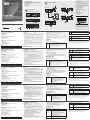
CE680L/CE690L (Local Unit) Front View
1. KVM Port Section
2. RS-232 Serial Port
3. USB Type B Port
4. Operation Mode Pushbutton
5. LEDs
CE680R/CE690R (Remote Unit) Front View
1. RS-232 Serial Port
2. Wake Up PC Pushbutton
3. Operation Mode Pushbutton
4. LEDs
CE680/CE690 (Local/Remote Unit) Rear View
1. Cable Tie Slot
2. Power Jack
3. USB Ports (for Keyboard / Mouse)
4. Audio Ports (Speakers / Mic)
5. USB Port (for Touch Panel)
6. DVI Output Port
7. Optical In / Out Port*
*The ber modules are color-coded as follows:
CE680L CE680R CE690L CE690R
Brown Yellow Purple White
Description de l’appareil
A
CE680L/CE690L (unité locale) – Vue avant
1. Section des ports KVM
2. Port série RS-232
3. Port USB de type B
4. Bouton de sélection du mode de fonctionnement
5. Voyants
CE680R/CE690R (unité distante) – Vue avant
1. Port série RS-232
2. Bouton de mise sous tension d’ordinateur à distance
3. Bouton de sélection du mode de fonctionnement
4. Voyants
CE680/CE690 (unité locale/unité distante) – Vue arrière
1. Emplacement de l'attache de câble
2. Prise d’alimentation
3. Ports USB (pour clavier / souris)
4. Ports audio (haut-parleurs / micro)
5. Port USB (pour écran tactile)
6. Port de sortie DVI
7. Port d’entrée/sortie optique*
*Les modules sont identi ables grâce au code de couleur suivant :
CE680L CE680R CE690L CE690R
Marron Jaune Violet Blanc
Hardwareübersicht
A
CE680L/CE690L (lokales Gerät) Vorderseite
1. KVM-Portabschnitt
2. Serieller RS-232-Port
3. USB-Anschluss, Typ B
4. Betriebsmodus-Auswahltaste
5. LED-Anzeigen
CE680R/CE690R (entferntes Gerät) Vorderseite
1. Serieller RS-232-Port
2. PC Wakeup-Taste
3. Betriebsmodus-Auswahltaste
4. LED-Anzeigen
CE680/CE690 (lokales Gerät/entferntes Gerät) Rückseite
1. Kabeldurchführung
2. Stromeingangsbuchse
3. USB-Ports (für Tastatur / Maus)
4. Audioports (Lautsprecher / Mikrofon)
5. USB-Port (für berührungsemp ndliches Feld - Touchpanel)
6. DVI-Ausgang
7. Ein-/Ausgang für Lichtwellenleiter*
* Die Lichtwellenleitermodule sind farbig wie folgt gekennzeichnet:
CE680L CE680R CE690L CE690R
Braun Gelb Violett Weiß
Presentación del hardware
A
CE680L/CE690L (unidad local) Vista frontal
1. Sección de puertos KVM
2. Puerto serie RS-232
3. Puerto USB de tipo B
4. Botón de modo operativo
5. Indicadores LED
CE680R/CE690R (unidad remota) Vista frontal
1. Puerto serie RS-232
2. Botón de reanudación del PC (PC Wakeup)
3. Botón de modo operativo
4. Indicadores LED
CE680/CE690 (unidad local/unidad remota) Vista frontal
1. Ranura para cables
2. Entrada de alimentación
3. Puertos USB (para teclado/mouse)
4. Puertos de audio (altavoces / micrófono)
5. Puerto USB (para panel táctil)
6. Puerto de salida DVI
7. Entrada y salida de bra óptica*
* Los módulos de bra óptica vienen codi cados por colores como sigue:
CE680L CE680R CE690L CE690R
Marrón Amarillo Violeta Blanco
Hardware
A
CE680L/CE690L (unità locale) – vista anteriore
1. Sezione delle porte KVM
2. Porta seriale RS-232
3. Porta USB tipo B
4. Pulsante della modalità operativa
5. LED
CE680R/CE690R (unità remota) – vista anteriore
1. Porta seriale RS-232
2. Pulsante di attivazione PC
3. Pulsante della modalità operativa
4. LED
CE680/CE690 (unità locale/unità remota) – vista posteriore
1. Alloggiamento della giunzione del cavo
2. Presa d’alimentazione
3. Porte USB (tastiera/mouse)
4. Porte audio (altoparlanti/microfono)
5. Porta USB (per il touch panel)
6. Porta dell’uscita DVI
7. Porta ingresso/uscita ottica*
*I moduli in bra hanno i seguenti codici colore:
CE680L CE680R CE690L CE690R
Marrone Giallo Viola Bianco
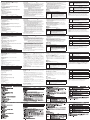
Hardware Installation
B
KVM Function
Steps 1–6 are the primary steps for installing your CE680 / CE690, and utilizing
the basic KVM functions.
1. Using the Custom KVM cable supplied with this unit, plug the connectors into
their appropriate ports on the front panel of the Local Unit (CE680L / CE690L).
2. Plug the connectors on the other end of the Custom KVM cable into the
appropriate ports on the local computer. Each connector is marked with an
appropriate icon to indicate which it is.
Note: If you are combining the CE680 / CE690 with a KVM switch, the other
end of the DVI KVM cable plugs into the appropriate ports on the KVM
switch.
3. Using a Fiber Optic cable (LC, Single Mode), connect the Local and Remote
units via the CE680L (Brown) / CE680R (Yellow) / CE690L (Purple) / CE690R
(White) Optical In/Out ports.
4. Connect the local console devices (mouse, keyboard, monitor, speakers,
microphone) into the appropriate ports on the rear panel of the CE680L /
CE690L.
5. Connect the remote console devices (mouse, keyboard, monitor, speakers,
microphone) into the appropriate ports on the rear panel of the CE680R /
CE690R.
6. Plug each of the power adapters (supplied with this package) to a power
source; plug the other ends into the CE680L / CE690L and CE680R / CE690R
Power Jack..
RS-232 Function (Optional)
Steps 7–8 are for incorporating a serial terminal or other serial devices into your
Installation du matériel
B
Fonction KVM
Les étapes 1 à 6 sont les principales étapes à suivre pour installer votre système
CE680 / CE690 et pouvoir utiliser les fonctions KVM de base.
1. Branchez les connecteurs du câble KVM personnalisé fourni avec l'appareil
dans les ports correspondants situés à l'avant de l’unité locale (CE680L /
CE690L).
2. Insérez les connecteurs de l'autre extrémité du câble KVM personnalisé dans
les ports correspondants de l'ordinateur local. Chaque connecteur comporte
une icône permettant de le distinguer facilement.
Remarque : si vous combinez le système CE680 / CE690 avec un
commutateur KVM, insérez l'autre extrémité du câble DVI KVM
dans les ports correspondants du commutateur KVM.
3. Avec un câble à bre optique (LC, monomode), connectez les unités locale
et distance aux ports d’entrée/sortie optiques du CE680L (marron) / CE680R
(jaune) / CE690L (violet) / CE690R (blanc).
4. Connectez les appareils de la console locale (souris, clavier, écran, haut-
parleurs, microphone) aux ports correspondants situés à l’arrière de l’unité
CE680L / CE690L.
5. Connectez les appareils de la console distante (souris, clavier, écran, haut-
parleurs, microphone) aux ports correspondants situés à l’arrière de l’unité
CE680R / CE690R.
6. Branchez chacun des adaptateurs secteur fournis sur une source
d’alimentation ; branchez les autres extrémités sur la prise d’alimentation de
l’unité CE680L / CE690L et de l’unité CE680R / CE690R.
Fonction RS-232 (facultatif)
Les étapes 7 et 8 vous permettent d’incorporer un terminal série ou d’autres
périphériques série dans votre installation. Procédez comme suit :
Hardware installieren
B
KVM-Funktion
Die Schritte 1 bis 6 sind die grundlegenden Schritte zur Installation Ihres CE680 /
CE690, sodass die KVM-Grundfunktionen sichergestellt sind.
1. Verbinden Sie die geeigneten Stecker des mitgelieferten, individuellen KVM-
Kabels mit den Buchsen auf der Vorderseite des lokalen Gerätes (CE680L /
CE690L).
2. Verbinden Sie die Stecker am anderen Ende des individuellen KVM-Kabels
mit den betreffenden Ports des lokalen Computers. Jeder Stecker ist durch
ein entsprechendes Symbol gekennzeichnet.
Hinweis: Wenn Sie den CE680 / CE690 mit einem KVM-Switch kombinieren
möchten, schließen Sie das andere Ende des DVI-KVM-Kabels an
die entsprechenden Ports des KVM-Switches an.
3. Verbinden Sie die beiden Geräte (lokales und entferntes Gerät) mit einem
Lichtwellenleiter (LC, einfacher Mode). Dazu verbinden Sie die Ports Optical
In/Out des CE680L (braun) / CE680R (gelb) / CE690L (violett) / CE690R
(weiß).
4. Verbinden Sie die Geräte der lokalen Konsole (Maus, Tastatur, Bildschirm,
Lautsprecher und Mikrofon) mit den Ports auf der Rückseite des CE680L /
CE690L.
5. Verbinden Sie die Geräte der entfernten Konsole (Maus, Tastatur, Bildschirm,
Lautsprecher und Mikrofon) mit den Ports auf der Rückseite des CE680R /
CE690R.
6. Verbinden Sie je ein Netzteil (im Lieferumfang enthalten) mit einer Steckdose
und das Netzkabel mit der Stromeingangsbuchse des CE680L / CE690L
sowie CE680R / CE690R.
RS-232-Funktion (optional)
Die Schritte 7 bis 8 beschreiben die Einbindung eines seriellen Terminals oder
eines anderen seriellen Gerätes in die Installation. Gehen Sie folgendermaßen
vor:
Instalar el hardware
B
Función KVM
Los pasos 1 a 6 son los pasos básicos para instalar el CE680 / CE690 y poder
utilizar las funciones KVM básicas.
1. Inserte los conectores del cable KVM personalizado incluido con el dispositivo
en los puertos correspondientes del panel frontal de la unidad local (CE680L /
CE690L).
2. Inserte los conectores del otro extremo del cable KVM en los puertos
correspondientes de la computadora local. Cada conector viene marcado con
un icono correspondiente.
Nota: si combina el CE680 / CE690 con un conmutador KVM, inserte
los conectores del otro extremo del cable KVM DVI en los puertos
correspondientes del conmutador KVM.
3. Utilice un cable de bra óptica (LC, modo simple) para interconectar las
unidades local y remota a través de los puertos Optical In/Out del CE680L
(marrón) / CE680R (amarillo) / CE690L (violeta) / CE690R (blanco).
4. Conecte los dispositivos de la consola local (mouse, teclado, monitor,
altavoces y micrófono) a los puertos correspondientes del panel posterior de
la unidad CE680L / CE690L.
5. Conecte los dispositivos de la consola remota (mouse, teclado, monitor,
altavoces y micrófono) a los puertos correspondientes del panel posterior de
la unidad CE680R / CE690R.
6. Conecte cada uno de los adaptadores de alimentación incluidos a una toma
eléctrica y el cable de alimentación del adaptador a la entrada de alimentación
del CE680L / CE690L y CE680R / CE690R.
Función RS-232 (opcional)
Los pasos 7 a 8 describen la implementación de un terminal serie u otros
dispositivos serie en la instalación. Proceda como se indica a continuación:
7. Para controlar dispositivos serie y/o emplear la función de reanudación del PC
Installazione dell’hardware
B
Funzione KVM
I passaggi da 1 a 6 sono quelli principali per installare il CE680/CE690 e
utilizzare le funzioni KVM di base.
1. Inserire i connettori appropriati del cavo KVM personalizzato fornito con
questa unità nelle relative porte sul lato anteriore dell’unità locale (CE680L/
CE690L).
2. Inserire i connettori all’altra estremità del cavo KVM personalizzato nelle
relative porte del computer locale. Ogni connettore è contrassegnato da
un’icona appropriata che lo identi ca.
Nota: Nel caso in cui si stia collegando il CE680/CE690 a uno switch KVM,
connettere l’altra estremità del cavo DVI KVM nelle relative porte dello
switch KVM.
3. Utilizzare un cavo a bra ottica (LC, modalità singola), collegare le unità locali
e remote tramite le porte di ingresso/uscita ottica del CE680L (marrone)/
CE680R (giallo)/CE690L(viola)/CE690R(bianco).
4. Collegare i dispositivi della console locale (mouse, tastiera, monitor, microfono
e altoparlanti) alle porte sul retro del CE680L/CE690L.
5. Collegare i dispositivi della console remota (mouse, tastiera, monitor,
microfono e altoparlanti) alle porte sul retro del CE680R/CE690R.
6. Collegare ciascuno degli alimentatori (in dotazione) a una fonte di
alimentazione, quindi collegare l’altra estremità alla presa d’alimentazione del
CE680L/CE690L e CE680R/CE690R.
Funzione RS-232 (opzionale)
I passaggi 7 e 8 servono ad aggiungere un terminale seriale o altri dispositivi
seriali all'installazione. Procedere come segue:
7. Per controllare i dispositivi seriali e/o la funzione Attivazione PC, collegare un
computer locale alla porta seriale RS-232 sull’unità locale.
8. Collegare un controller hardware/software alla porta seriale RS-232 sull’unità
remota.
installation. Do the following steps:
7. For control of serial devices and/or to use Wake Up PC feature, connect a
local computer to the RS-232 Serial port on the local unit.
8. Connect a Hardware/Software Controller to the RS-232 Serial port on the
remote unit.
Touchscreen Panel Function (Optional)
Steps 9–10 are for connecting/managing a touchscreen panel to your installation.
Do the following steps:
9. Connect a computer to the USB Type B port on the front panel of the CE680L
/ CE690L for touchscreen panel control.
10. Connect your touchscreen panel device(s) to the USB Type A ports on the
rear panels of the CE680L / CE690L and CE680R / CE690R.
Operation
LED Display
CE680L / CE690L (Local Unit)
LED Indication
Local
(Green)
• Lights when the local console is active (the Remote LED is off).
• Lights also when in Hotkey Setting Mode. The remote console’s
keyboard and mouse are disabled.
• If no Hotkey is detected after 5 seconds, device goes on Auto
operating mode and LED tu rns off.
• Turns off when the remote console is active (the Remote LED turns
on).
• Flashes when in Auto operating mode.
7. Pour contrôler des périphériques série et/ou utiliser la fonctionnalité de mise
sous tension d'ordinateur à distance, reliez un ordinateur local au port série
RS-232 de l’unité locale.
8. Connectez un contrôleur matériel/logiciel au port série RS-232 de l’unité
distante.
Fonction cran tactile (facultatif)
Les étapes 9 et 10 permettent de connecter/gérer un écran tactile au sein de
votre installation. Procédez comme suit :
9. Connectez un ordinateur au port USB Type B du panneau avant de l’unité
CE680L / CE690L pour permettre le contrôle par écran tactile.
10. Connectez votre ou vos périphériques à écran tactile au port USB Type A du
panneau arrière des unités CE680L / CE690L et CE680R / CE690R.
Fonctionnement
Affi chage des voyants
CE680L / CE690L (unités locales)
Voyant Indication
Voyant
local
(vert)
• S’allume lorsque la console locale est active (le voyant distant est
éteint).
• S’allume également en mode de raccourcis clavier. Le clavier et
la souris de la console distante sont désactivés.
• Si aucun raccourci clavier n’est détecté au bout de 5 secondes,
l’appareil passe en mode de fonctionnement Auto et le voyant
s’éteint.
• S’éteint lorsque la console distante est active (le voyant distant est
allumé).
• Clignote en mode de fonctionnement auto.
7. Zur Steuerung serieller Geräte bzw. zur Verwendung der PC-Wakeup-
Funktion verbinden Sie den lokalen Computer mit dem seriellen Port RS-232
Serial des lokalen Gerätes.
8. Verbinden Sie einen Hardware-/Software-Controller mit dem Anschluss RS-
232 Serial der Empfangseinheit.
Touchscreen-Funktion (optional)
Die Schritte 9 bis 10 beschreiben den Anschluss bzw. die Verwaltung eines
Touchscreens in Ihrer Installation. Gehen Sie folgendermaßen vor:
9. Verbinden Sie einen Computer mit dem Port USB Type B auf der Vorderseite
des CE680L / CE690L, um das System per Touchscreen bedienen zu können.
10. Verbinden Sie Ihren Touchscreen mit dem Port USB Type A auf der
Rückseite des CE680L / CE690L sowie CE680R / CE690R.
Bedienung
LED-Anzeige
CE680L / CE690L (lokales Gerät)
LED-Anzeigen Anzeige
Local (grün)
• Leuchtet, wenn die lokale Konsole aktiv ist (die LED
Remote leuchtet nicht).
• Leuchtet ebenfalls bei der Hotkey-Einrichtung. Die
Tastatur und die Maus der entfernten Konsole sind
deaktiviert.
• Wird innerhalb von 5 Sekunden keine Hotkey-
Eingabe erkannt, wechselt das Gerät wieder in den
Automatikbetrieb, und die LED erlischt.
• Erlischt, wenn die entfernte Konsole aktiv ist (die LED
Remote leuchtet).
• Blinkt bei Automatikbetrieb.
(PC Wakeup), conecte el puerto RS-232 Serial de la unidad local a un puerto
serie de la computadora local.
8. Conecte una controladora de hardware/software al puerto RS-232 Serial de la
unidad remota.
Función de panel táctil (opcional)
Los pasos 9 a 10 describen la conexión/administración de una pantalla táctil en
su instalación. Proceda como se indica a continuación:
9. Conecte una computadora al puerto USB Type B del panel frontal del CE680L
/ CE690L para poder controlar el sistema con una pantalla táctil.
10. Conecte su(s) dispositivo(s) de pantalla táctil al puerto USB Type A de los
paneles posteriores del CE680L / CE690L y del CE680R / CE690R.
Funcionamiento
Indicador LED
CE680L / CE690L (unidad local)
Indicador LED Indicación
Local (verde)
• Se ilumina cuando la consola local está activa (el indicador
Remote está apagado).
• También se ilumina en el modo de teclas de acceso
directo. El teclado y el mouse de la consola remota
están desactivados.
• Si tras 5 segundos no se ha detectado ninguna tecla de
acceso directo, el dispositivo pasa al modo automático y
el indicador se apaga.
• Se apaga cuando la consola remota está activa (el
indicador Remote está encendido).
• Parpadea en el modo operativo automático.
Funzione pannello touchscreen (opzionale)
I passaggi 9 e 10 servono per collegare/gestire un pannello touchscreen
all’installazione. Procedere come segue:
9. Collegare un computer alla porta USB di tipo B sul pannello anteriore del
CE680L/CE690L per controllare il pannello touchscreen.
10. Collegare i pannelli touchscreen alle porte USB di tipo A sui pannelli
posteriori del CE680L/CE690L e CE680R/CE690R.
Funzionamento
Indicatore LED
CE680L / CE690L (unità locale)
LED Indicazione
Locale (verde)
• Si accende quando la console locale è attiva (il LED
dell’unità remota è spento).
• Si accende anche in modalità impostazione tasti di
scelta rapida. La tastiera e il mouse della consolle
remota sono disattivati.
• Se non viene rilevato un tasto di scelta rapida dopo
5 secondi, il dispositivo entra in modalità operativa
automatica e il LED si spegne.
• Si spegne quando la console remota è attiva (il LED
dell’unità remota si accende).
• Lampeggia in modalità operativa automatica.
Remota (verde)
• Si accende quando la console remota è attiva (il LED
dell’unità locale è spento).
• Si spegne quando la console locale è attiva (il LED
dell’unità locale si accende).
• Lampeggia in modalità operativa automatica.
Remote
(Green)
• Lights when the remote console is active (the Local LED is off).
• Turns off when the local console is active (the Local LED turns on).
• Flashes when in Auto operating mode.
CE680R / CE690R (Remote Unit)
LED Indication
Link
(Green)
• Lights to indicate that the connection to the Local unit is active.
• Flashes when there is a problem with the connection to the Local
unit and the “Remote LED” is off.
Remote
(Green)
• Lights to indicate that the remote console is active.
• Turns off when the local console is active.
• Flashes when in Auto operating mode.
Wake Up PC
Use an RS-232 cable to connect the PC at local site to the CE680L / CE690L.
When at the remote console and you want to wake a computer on the local site,
use the Wakeup PC Pushbutton on the front panel of the CE680R / CE690R
*
.
*The PC’s BIOS should support RS-232 wake up function.
Voyant
distant
(vert)
(Remote)
• S’allume lorsque la console distante est active (le voyant local est
éteint).
• S’éteint lorsque la console locale est active (le voyant local est
allumé).
• Clignote en mode de fonctionnement auto.
CE680R / CE690R (unités distantes)
Voyant Indication
Voyant
de liaison
(vert)
(Link)
• S’allume pour indiquer que la connexion à l’unité locale est
active.
• Clignote pour signaler un problème au niveau de la connexion à
l’unité locale. Le voyant distant est alors éteint.
Voyant
distant
(vert)
(Remote)
• S’allume pour indiquer que la console distante est active.
• S’éteint lorsque la console locale est active.
• Clignote en mode de fonctionnement auto.
Mise sous tension d’ordinateur à distance
Utilisez un câble RS-232 pour connecter l’ordinateur du site local au CE680L /
CE690L. Si vous souhaitez réveiller un ordinateur du site local depuis la console
distante, utilisez le bouton de mise sous tension d’ordinateur à distance situé sur
le panneau avant du CE680R / CE690R.*
* Le BIOS de l’ordinateur doit prendre en charge la fonction de mise sous tension
RS-232.
Remote (grün)
• Leuchtet, wenn die entfernte Konsole aktiv ist (die LED
Local leuchtet nicht).
• Erlischt, wenn die lokale Konsole aktiv ist (die LED Local
leuchtet).
• Blinkt bei Automatikbetrieb
CE680R / CE690R (Empfangsgerät)
LED-Anzeigen Anzeige
Verbindung
(grün)
• Leuchtet stetig, wenn die Verbindung zum lokalen Gerät
aktiv ist.
• Blinkt, wenn ein Problem mit der Verbindung zum lokalen
Gerät besteht – die LED “Remote” leuchtet nicht.
Remote (grün)
• Leuchtet, wenn die entfernte Konsole aktiv ist.
• Erlischt, wenn die lokale Konsole aktiv ist.
• Blinkt bei Automatikbetrieb.
PC Wakeup-Funktion
Verbinden Sie einen lokalen PC über ein RS-232-Kabel mit dem CE680L /
CE690L. Wenn Sie sich an der Konsole der Gegenstelle be nden und den
lokalen Computer aktivieren möchten, drücken Sie die PC Wakeup-Taste auf der
Gerätevorderseite des CE680R / CE690R.*
* Das BIOS des PCs muss die Wakeup-Funktion über RS-232 unterstützen.
Remote (verde)
• Se ilumina cuando la consola remota está activa (el
indicador Local está apagado).
• Se apaga cuando la consola local está activa (el indicador
Local está encendido).
• Parpadea en el modo operativo automático.
CE680R / CE690R (unidad remota)
Indicador LED Indicación
Link (verde)
• Se ilumina cuando la conexión con la unidad local está
activa.
• Parpadea cuando existe un problema de conexión con la
unidad local y el indicador “Remote” está apagado.
Remote (verde)
• Se ilumina cuando la consola remota está activa.
• Se apaga cuando la consola local está activa.
• Parpadea en el modo operativo automático.
Función de reanudación del PC (PC Wakeup)
Emplee un cable RS-232 para conectar el PC local al CE680L / CE690L. Cuando
se encuentre en la consola remota, pulse el botón de reanudación del PC del
panel anterior del CE680R / CE690R para reactivar la computadora local.*
* El BIOS del PC debe admitir la función de reanudación por RS-232.
CE680R / CE690R (unità remota)
LED Indicazione
Collegamento
(verde)
• Si accende per indicare che il collegamento con l’unità
locale è attivo.
• Lampeggia per indicare che il collegamento con l’unità
locale presenta dei problemi e il LED dell’unità remota è
spento
Remota (verde)
• Si accende a indicare che la console remota è attiva.
• Si spegne quando la console locale è attiva.
• Lampeggia in modalità operativa automatica.
Attivazione PC
Utilizzare un cavo RS-232 per collegare il PC locale al CE680L/CE690L. Se si
desidera attivare un computer locale dalla console remota, utilizzare il pulsante
Attivazione PC sul pannello anteriore del CE680R / CE690RQ.*
*Il BIOS del PC deve supportare la funzione di attivazione via RS-232
B
Package Contents
1 CE680L or CE690L DVI Optical KVM Extender (Local Unit)
1 CE680R or CE690R DVI Optical KVM Extender (Remote Unit)
1 Custom KVM Cable Set (1.8m)
1 USB Cable (1.8m)
2 Power Adapters
1 Mounting Kit
1 User Instructions
CE680L /CE690L (Local Unit) Front View
Front View Rear View
CE680R/CE690R (Remote Unit) Front View
CE680/CE690 (Local/Remote Unit) Rear View
Hardware Installation
© Copyright 2013 ATEN
®
International Co., Ltd.
ATEN and the ATEN logo are trademarks of ATEN International Co., Ltd. All rights reserved.
All other trademarks are the property of their respective owners.
This product is RoHS compliant.
Part No. PAPE-1223-B30G Printing Date: 12/2013
DVI Optical KVM Extender /
Long Distance DVI Optical KVM Extender
Quick Start Guide
CE680/CE690
CE680/CE690 DVI Optical KVM Extender / Long Distance DVI Optical KVM Extender Quick Start Guide
www.aten.com
Système d’extension KVM DVI optique / Système d’extension KVM DVI optique longue distance – Guide de démarrage rapide
www.aten.com
Optische KVM-Verlängerung für DVI / Optische KVM-Verlängerung für DVI und lange Übertragungswege Kurzanleitung
www.aten.com
Alargador KVM DVI por bra óptica / Alargador KVM DVI de larga distancia por bra óptica Guía rápida
www.aten.com
Estensore KVM ottico DVI/Estensore KVM ottico DVI a lunga distanza – guida rapida
www.aten.com
Simply Better Connections
Important Notice
Considering environmental protection, ATEN
does not provide a fully printed user manual
for this product. If the information contained
in the Quick Start Guide is not enough for
you to configure and operate your product,
please visit our website www.aten.com, and
download the full user manual.
Online Registration
http://eservice.aten.com
Technical Phone Support
International:
886-2-86926959
North America:
1-888-999-ATEN Ext: 4988
United Kingdom:
44-8-4481-58923
All information, documentation, firmware,
software utilities, and speci cations contained in
this package are subject to change without prior
noti cation by the manufacturer. Please visit our
website http://www.aten.com/download/?cid=dds
for the most up-to-date versions.
The following contains information that relates
to China:
1 2 3 4
5
1 2 3 4 5 6 7
1 2 3
4
6
10
3
3
4
6
5
Touchscreen
10
Touchscreen
Fiber Optic cable
CE680L / CE690L
CE680R / CE690R
Local PC
RS-232
1
2
7
9
Custom KVM
cable set
CE680L / CE690L
8
CE680R / CE690R
A
Hardware Review
La pagina si sta caricando...
-
 1
1
-
 2
2


in altre lingue
- English: ATEN CE680 Quick start guide
- français: ATEN CE680 Guide de démarrage rapide
- español: ATEN CE680 Guía de inicio rápido
- Deutsch: ATEN CE680 Schnellstartanleitung
- русский: ATEN CE680 Инструкция по началу работы
- português: ATEN CE680 Guia rápido
- 日本語: ATEN CE680 クイックスタートガイド
Documenti correlati
-
ATEN CE750A Guida Rapida
-
ATEN CE700A Guida Rapida
-
-
ATEN USB DVI Dual View Cat 5 KVM Extender (1024 x 768@60m) Guida Rapida
-
ATEN CE774 Guida Rapida
-
ATEN CE600 Guida Rapida
-
-
ATEN CE610 Guida Rapida
-
ATEN KE6900R Guida Rapida
-
ATEN CE750 Guida Rapida