11
¡Nie dieses Gerät in Booten oder Fahrzeu-
gen verwenden.
¡Die Empfehlungen des Arbeitsplattenher-
stellers beachten.
Sichere Montage
Beachten Sie diese Sicherheitshinweise, wenn Sie
das Gerät montieren.
Nur bei fachgerechtem Einbau entsprechend der
Montageanleitung ist die Sicherheit beim Gebrauch
gewährleistet. Der Installateur ist für das einwand-
freie Funktionieren am Aufstellungsort verantwortlich.
WARNUNG‒Gefahr durch Magnetismus!
Das Gerät enthält Permanentmagnete. Diese können
elektronische Implantate, z.B. Herzschrittmacher
oder Insulinpumpen beeinflussen.
▶Personen mit elektronischen Implantaten müssen
10cm Mindestabstand zum Gerät einhalten.
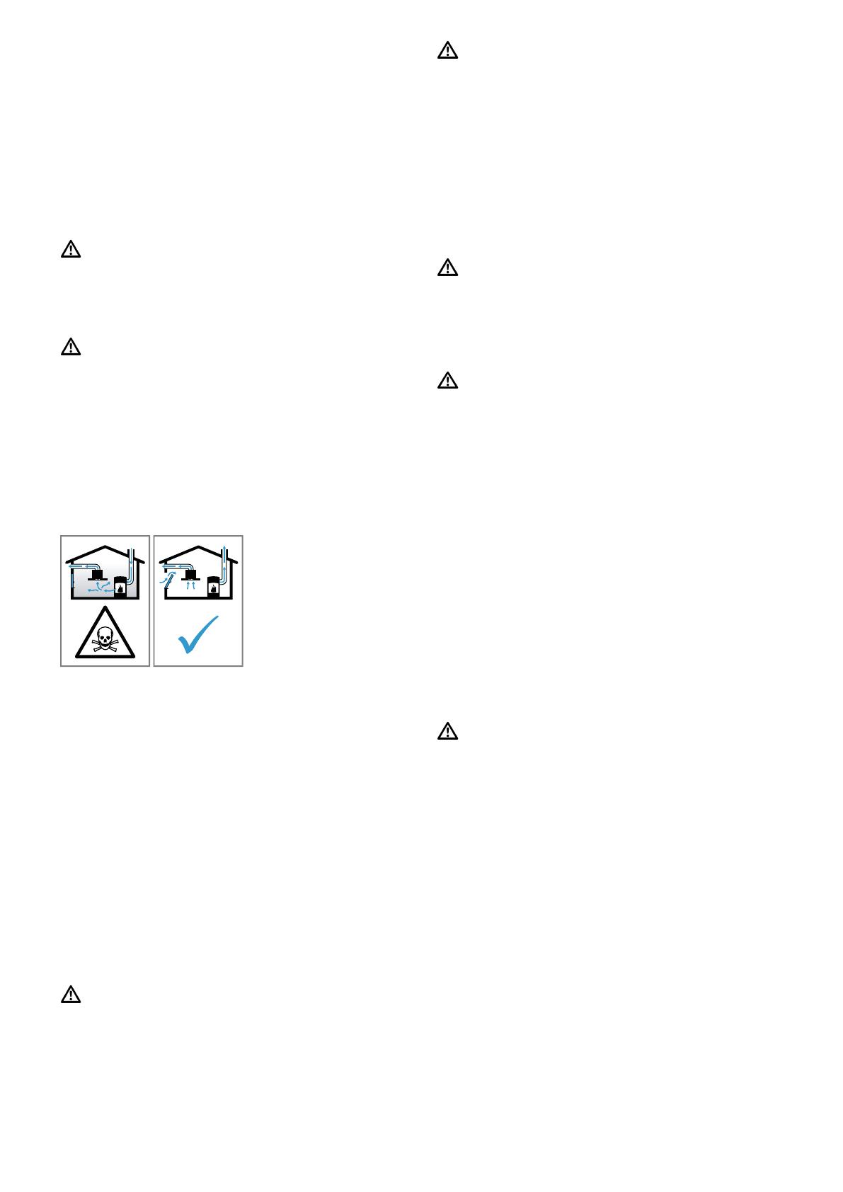
WARNUNG‒Vergiftungsgefahr!
Zurückgesaugte Verbrennungsgase können zu Ver-
giftungen führen. Raumluftabhängige Feuerstätten (z.
B. gas-, öl-, holz- oder kohlebetriebene Heizgeräte,
Durchlauferhitzer, Warmwasserbereiter) beziehen
Verbrennungsluft aus dem Aufstellraum und führen
die Abgase durch eine Abgasanlage (z. B. Kamin)
ins Freie. In Verbindung mit einer eingeschalteten
Dunstabzugshaube wird der Küche und den benach-
barten Räumen Raumluft entzogen. Ohne ausrei-
chende Zuluft entsteht ein Unterdruck. Giftige Gase
aus dem Kamin oder Abzugsschacht werden in die
Wohnräume zurückgesaugt.
▶Immer für ausreichend Zuluft sorgen, wenn das
Gerät im Abluftbetrieb gleichzeitig mit einer raum-
luftabhängigen Feuerstätte verwendet wird.
▶Ein gefahrloser Betrieb ist nur dann möglich, wenn
der Unterdruck im Aufstellraum der Feuerstätte
4Pa(0,04mbar) nicht überschreitet. Dies kann
erreicht werden, wenn durch nicht verschließbare
Öffnungen, z. B. in Türen, Fenstern, in Verbindung
mit einem Zuluft- / Abluftmauerkasten oder durch
andere technische Maßnahmen, die zur Verbren-
nung benötigte Luft nachströmen kann. Ein Zu-
luft-/Abluftmauerkasten allein stellt die Einhaltung
des Grenzwertes nicht sicher.
▶Ziehen Sie in jedem Fall den Rat des zuständigen
Schornsteinfegermeisters hinzu, der den gesam-
ten Lüftungsverbund des Hauses beurteilen kann
und Ihnen die passende Maßnahme zur Belüftung
vorschlägt.
▶Wird das Gerät ausschließlich im Umluftbetrieb
eingesetzt, ist der Betrieb ohne Einschränkung
möglich.
WARNUNG‒Brandgefahr!
Die Fettablagerungen im Fettfilter können sich ent-
zünden.
▶In der Nähe des Gerätes nie mit offener Flamme
arbeiten (z.B. flambieren).
▶Gerät nur dann in der Nähe einer Feuerstätte für
feste Brennstoffe (z.B. Holz oder Kohle) installie-
ren, wenn eine geschlossene, nicht abnehmbare
Abdeckung vorhanden ist. Es darf keinen Funken-
flug geben.
WARNUNG‒Verletzungsgefahr!
Veränderungen am elektrischen oder mechanischen
Aufbau sind gefährlich und können zu Fehlfunktio-
nen führen.
▶Keine Veränderungen am elektrischen oder me-
chanischen Aufbau durchführen.
Teile, die während der Montage zugänglich sind,
können scharfkantig sein und zu Schnittverletzungen
führen.
▶Schutzhandschuhe tragen
Das Gerät ist schwer.
▶Zum Bewegen des Gerätes sind 2 Personen erfor-
derlich.
▶Nur geeignete Hilfsmittel verwenden.
WARNUNG‒Erstickungsgefahr!
Kinder können sich Verpackungsmaterial über den
Kopf ziehen oder sich darin einwickeln und ersti-
cken.
▶Verpackungsmaterial von Kindern fernhalten.
▶Kinder nicht mit Verpackungsmaterial spielen las-
sen.
WARNUNG‒Vergiftungsgefahr!
Zurückgesaugte Verbrennungsgase können zu Ver-
giftungen führen.
▶Die Abluft nicht in einen Rauchkamin oder einen
Abgaskamin abgeben, der in Betrieb ist.
▶Die Abluft nicht in einen Schacht abgeben, der zur
Entlüftung von Aufstellungsräumen von Feuerstät-
ten dient.
▶Soll die Abluft in einen Rauchkamin oder Abgas-
kamin geführt werden, der nicht in Betrieb ist,
muss die Zustimmung des zuständigen Schorn-
steinfegermeisters eingeholt werden.
Zurückgesaugte Verbrennungsgase können zu Ver-
giftungen führen.
▶Wenn eine Dunstabzugshaube mit einer raumluft-
abhängigen Feuerstätte installiert wird, muss die
Stromzuführung der Dunstabzugshaube mit einer
geeigneten Sicherheitsschaltung versehen wer-
den.
Hinweise zum elektrischen Anschluss
Um das Gerät sicher elektrisch anschließen zu kön-
nen, beachten Sie diese Hinweise.
WARNUNG‒Stromschlaggefahr!
Die Trennung des Geräts vom Stromnetz muss je-
derzeit möglich sein. Das Gerät darf nur an eine vor-
schriftsmäßig installierte Anschlussdose angeschlos-
sen werden.
▶In der festverlegten elektrischen Installation muss
eine allpolige Trennvorrichtung nach den Bedin-
gungen der Überspannungskategorie III und nach
den Errichtungsbestimmungen eingebaut werden.
▶Nur eine Elektrofachkraft darf die festverlegte elek-
trische Installation ausführen. Wir empfehlen einen
Fehlerstromschutzschalter (FI-Schalter) im Strom-
kreis der Geräteversorgung zu installieren.
¡Das Anschlusskabel nicht knicken oder einklem-
men und von scharfen Kanten fernhalten.
¡Das Anschlusskabel so verlegen, dass es nicht
das heiße Gerätegehäuse berührt.
¡Nur das mit dem Gerät mitgelieferte oder vom
technischen Kundendienst gelieferte Anschlusska-
bel verwenden.
¡Dieses Gerät entspricht den EG-Funkentstörbe-
stimmungen.
¡Das Gerät entspricht der Schutzklasse 1. Daher
das Gerät nur mit Schutzleiter-Anschluss verwen-
den.


