La pagina si sta caricando...

This is an unvented gas-red heater. It uses air
(oxygen) from the room in which it is installed.
Provisions for adequate combustion and venti-
lation air must be provided. Refer to Page 7.
INSTALLER: Leave this manual with the appliance.
CONSUMER: Retain this manual for future
reference.
• Do not store or use gasoline or other
ammable vapors and liquids in the
vicinity of this or any other appliance.
• WHAT TO DO IF YOU SMELL GAS
– Do not try to light any appliance.
– Do not touch any electrical switch; do
not use any phone in your building.
– Leave the building immediately.
– Immediately call your gas supplier from
a neighbor's phone. Follow the gas
supplier's instructions.
– If you cannot reach your gas supplier,
call the re department.
• Installation and service must be performed
by a qualied installer, service agency or
the gas supplier.
WARNING: If the information in this
manual is not followed exactly, a re or
explosion may result causing property
damage, personal injury or loss of life.
VFI Series Vent Free Gas Fireplace
Installation & Operating Instructions
Models: VFI33L(N/P)(V/I), VFI33C(N/P)(V/I)
Monessen • VFI33 Owner Manual • 20307670 • Rev H • 1/2020

VFI33 Vent Free Gas Fireplace System
2
Monessen • VFI33 Owner Manual • 20307670 • Rev H • 1/2020
CONTENTS
Thank you and congratulations on your purchase of a Monessen vent free gas replace.
PLEASE READ THE INSTALLATION AND OPERATION INSTRUCTIONS
BEFORE USING THE APPLIANCE.
IMPORTANT: Read all instructions and warnings carefully before starting installation.
Failure to follow these instructions may result in a possible re hazard and will void the warranty.
Important Safety Information ...................................... 3
Codes ....................................................................... 4
Product Features .......................................................... 5
Operation ................................................................. 5
Gas Pressures ......................................................... 5
Gas Specications And Orice Size ......................... 5
Ignition Controls ....................................................... 5
Pilot .......................................................................... 5
Thermal Generator ................................................... 5
Fireplace And Framing Dimensions ........................... 6
Fireplace And Framing Dimensions ......................... 6
Pre-Installation Information ......................................... 7
Framing Dimensions ................................................ 7
Getting Started ......................................................... 7
What You Will Need For Installation ......................... 7
Clearances And Height Requirements ....................... 8
Before Installing The Fireplace Insert ...................... 9
Heat Resistant Material ............................................ 9
Installation ................................................................... 10
Remove Screen ..................................................... 10
Install Canopy ........................................................ 10
Secure Heater To Floor .......................................... 11
Connect Gas Line ....................................................... 12
Connecting The Gas Line ...................................... 12
Gas Pressure – Millivolt .............................................. 13
Checking Gas Pressure – Millivolt Control ............. 13
Electrical Wiring – Millivolt ......................................... 14
Connect Optional Wall Switch Or Thermostat ........ 14
Connect Remote Receiver ..................................... 15
Check System Operation ....................................... 15
Operating Instructions – Millivolt .............................. 16
For Your Safety Read Before Lighting ................... 16
What To Do If You Smell Gas ................................. 16
Lighting Pilot For The First Time ............................ 16
Lighting Pilot ..........................................................17
Lighting Burner ....................................................... 18
To Turn Off Gas ...................................................... 18
Check Gas Pressure – IPI ...................................... 19
Electrical Installation – IPI .......................................... 19
Electrical Wiring ..................................................... 19
Junction Box Wiring ............................................... 19
IPI System Wiring Diagram .................................... 20
Operating Instruction – IPI ......................................... 21
For Your Safety Read Before Lighting ................... 21
What To Do If You Smell Gas ................................. 21
Operating Instructions ............................................ 21
To Turn Off Gas To The Appliance ......................... 21
Operating And Indications ...................................... 22
Electrical Wiring – Fan ................................................ 23
Log Placement ............................................................ 24
Before You Begin ................................................... 24
Rock Wool Placement ............................................ 25
Install Berkley Oak Logs ........................................ 25
Install Highland Oak Logs ...................................... 27
Install Kentucky Wildwood Logs ............................28
Install Beachcomber and Riverwood Logs.............30
Fireglass Placement ..............................................31
Flame Appearance ................................................. 32
Visual Flame Check ............................................... 32
Check The Pilot Flame ........................................... 32
Thermostat And Millivolt Control ............................ 32
Operating Instructions ............................................ 32
Operating Instructions ............................................... 31
For Your Safety Read Before Lighting ................... 33
What To Do If You Smell Gas ................................. 33
Millivolt/Thermostat Control Lighting Instructions .. 34
To Turn Off Gas To Heater ..................................... 34
Match Lighting Instructions .................................... 34
Blower Operation ................................................... 34
Cleaning And Servicing ............................................. 36
Annual Cleaning And Inspection ............................ 36
Periodic Cleaning ................................................... 36
Troubleshooting ......................................................... 37
Replacement Parts ..................................................... 39
Firebox Assembly ................................................... 39
Millivolt Burner Assembly ....................................... 40
IPI Burner Assembly .............................................. 41
Berkley Oak Logs ................................................... 42
Beachcomber and Riverwood Logs........................43
Highland Oak Logs ................................................44
Kentucky Wildwood Logs ....................................... 45
Warranty ...................................................................... 46
►

VFI33 Vent Free Gas Fireplace System
3
Monessen • VFI33 Owner Manual • 20307670 • Rev H • 1/2020
ment instructions for proper installation.
13. Avoid any drafts that alter burner ame patterns. Do not
allow fans to blow directly into replace. Do not place
a blower inside burn area of rebox. Ceiling fans may
create drafts that alter burner ame patterns. Sooting
and improper burning will occur.
14. CAUTION: Candles, incense, oil lamps, etc. produce
combustion byproducts including soot. Vent-free
appliances will not lter or clean soot produced by
these types of products. In addition, the smoke and/or
aromatics (scents) may be re-burned in the vent-free
appliance which can produce odors. It is recommended
to minimize the use of candles, incense, etc. while the
vent-free appliance is in operation.
15. This is an unvented gas-fired heater. It uses air
(oxygen) from the room in which it is installed. Provi-
sions for adequate combustion and ventilation air must
be provided.
16. This heater shall not be installed in a room or space
unless the required volume of indoor combustion air is
provided by the method described in the National Fuel
Gas Code, ANSI Z223.1/NFPA 54, the International
Fuel Gas Code or applicable local codes.
17. Keep room area clear and free from combustible mate-
rials, gasoline and other ammable vapors and liquids.
18. Unvented gas heaters are a supplemental zone heater.
They are not intended to be the primary heating appli-
ance.
19. Unvented gas heaters emit moisture into the living
area. In most homes of average construction, this
does not pose a problem. In houses of extremely
tight construction, additional mechanical ventilation is
recommended.
IMPORTANT SAFETY INFORMATION
WARNING!
1. Due to high temperatures, the appliance should be
located out of trafc and away from furniture and
draperies.
2. Children and adults should be alerted to the hazard
of high surface temperature and should stay away
to avoid burns or clothing ignition.
3. Young children should be carefully supervised when
they are in the same room with the appliance.
4. Do not place clothing or other ammable material
on or near the appliance.
5. Any safety screen or guard removed for servicing
an appliance, must be replaced prior to operating
the heater.
6. Installation and repair should be done by a qualied
service person.
7. To prevent malfunction and/or sooting, an unvented
gas heater should be cleaned before use and at
least annually by a professional service person.
More frequent cleaning may be required due to
excessive lint from carpeting, bedding materials,
etc. It is imperative that control compartments,
burners and circulating air passageways be kept
clean.
INSTALLER
Please leave these instructions with the appliance.
OWNER
Please retain these instructions for future reference
.
8. CARBON MONOXIDE POISONING: Early signs of
carbon monoxide poisoning are similar to the u with
headaches, dizziness and/or nausea. If you have these
signs, obtain fresh air immediately. Have the heater
serviced as it may not be operating properly.
9. The installation must conform with local codes or, in
the absence of local codes, with the National Fuel
Gas Code, ANSI Z223.l/NFPA54.
10. This unit complies with the latest edition of ANSI
Z21.11.2, Unvented Heaters.
11. Do not install the heaters in a bathroom or bedroom.
12. Correct installation of the ceramic ber logs, proper
location of the heater, and annual cleaning are neces-
sary to avoid potential problems with sooting. Sooting,
resulting from improper installation or operation, can
settle on surfaces outside the replace. See log place-
WARNING!
• Any change to this heater or its controls can be dangerous.
• Improper installation or use of the heater can cause serious injury or death from re, burns,
explosion or carbon monoxide poisoning.
• Do not allow fans to blow directly into the replace. Avoid any drafts that alter burner ame
patterns.
• Do not use a blower insert, heat exchanger insert or other accessory, not approved for use with
this heater where applicable.

VFI33 Vent Free Gas Fireplace System
4
Monessen • VFI33 Owner Manual • 20307670 • Rev H • 1/2020
IMPORTANT SAFETY INFORMATION
20. During manufacturing, fabricating and shipping, various
components of this appliance are treated with certain
oils, lms or bonding agents. These chemicals are not
harmful but may produce annoying smoke and smells
as they are burned off during the initial operation of the
appliance; possibly causing headaches or eye or lung
irritation. This is a normal and temporary occurrence.
The initial break-in operation should last four hours
with the burner at the highest setting. Provide maxi-
mum ventilation by opening windows or doors to allow
odors to dissipate. Any odors remaining after this initial
break-in period will be slight and will disappear with
continued use.
21. Input ratings are shown in BTU per hour and are for
elevations up to 2,000 feet. For elevations above 2,000
feet, input ratings should be reduced 4 percent for each
1,000 feet above sea level. Refer to the National Fuel
Gas Code.
22. The appliance must be isolated from the gas supply
piping system by closing its equipment shutoff valve
during any pressure testing of the gas supply piping
system at test pressures equal to or less than 1/2 psig
(3.5 kPa).
23. Do not use this room heater if any part has been under
water. Immediately call a qualied service technician
to inspect the room heater and to replace any part of
the control system and any gas control which has been
under water.
24. Never burn solid fuels in a replace where a unvented
room heater is installed.
25. Always have a replace screen in place when the
appliance is in operation and, unless other provisions
for combustion air are provided, the screen must have
an opening(s) for induction of combustion air.
THIS APPLIANCE MAY BE INSTALLED IN AN
AFTER-MARKET, PERMANENTLY LOCATED,
MANUFACTURED (MOBILE) HOME, WHERE
NOT PROHIBITED BY LOCAL CODES.
THIS APPLIANCE IS ONLY FOR USE WITH THE
TYPE OF GAS INDICATED ON THE RATING
PLATE. THIS APPLIANCE IS NOT CONVERT-
IBLE FOR USE WITH OTHER GASES.
Nous recommandons que nos
appareils de chauffage au gaz
soient installés et entretenus par
des professionnels qui ont été
accrédités aux È.U. par le National
Fireplace Institute ® (NFI) comme
étant des spécialistes du NFI en
matièred’appareils de chauffage
au gaz.
CODES
Adhere to all local codes or, in their absence, the latest edition of THE NATIONAL FUEL GAS CODE ANSI Z223.1 or
NFPA54 which can be obtained from…
American National Standards Institute, Inc.
1430 Broadway
New York, NY 10018
or
National Fire Protection Association, Inc.
Batterymarch Park
Quincy, MA 02269
WARNING: Never connect unit to private
(non-utility) gas wells. This gas is commonly
known as wellhead gas.
WARNING: This product and the
fuels used to operate this product (liquid
propane or natural gas), and the products
of combustion of such fuels, can expose
you to chemicals including benzene, which
is known to the State of California to cause
cancer and reproductive harm. For more
information go to: www.P65Warnings.
ca.gov.

VFI33 Vent Free Gas Fireplace System
5
Monessen • VFI33 Owner Manual • 20307670 • Rev H • 1/2020
OPERATION
This unvented gas heater requires no outside venting and
burns cleanly with high heating efciency.
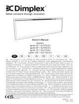
PRODUCT FEATURES
Figure 1. Unvented Gas Heater with Control Access Door Open
GAS PRESSURES
Control Fuel Millivolt T-stat
Regulator Pressure Natural 3.5" w.c.
Pilot Regulator Natural 3.5" w.c.
Max. Inlet Pressure Natural 10.5" w.c.
Min. Inlet Pressure Natural 5.0" w.c.
Regulator Pressure LP 10.0" w.c.
Max. Inlet Pressure LP 13.0" w.c.
Min. Inlet Pressure LP 11.0" w.c.
NOTE: For LP models an external regulator is required
to reduce supply pressure to a maximum of 13" w.c.
IGNITION CONTROLS
Piezo ignitor allows ignition of the pilot without the use of
matches or batteries.
Millivolt and EcoLogic
®
2.0 controls have four (4)
positions:
OFF - All gas to the gas logs is shut off at the
valve.
IGN - Valve position to light/maintain a standing
pilot.
ON - Valve position to turn ON/OFF log set with
remote switch/thermostat.
LOW/HI - Variable position to control ame height
(heat output). Both front and rear burners
are in operation to provide realistic glow
and yellow ame.
PILOT
The gas log heater is tted with a specially designed safety
pilot light (ODS assembly) which senses the amount of
oxygen available in the room and shuts the gas log heater
off if the oxygen level begins to drop below a satisfactory
level. The pilot can only be re-lit when adequate fresh air
is available.
THERMAL GENERATOR
The millivolt gas log pilot is tted with a millivolt generator
to provide power for remote activation.
VFI33 CONTROLS
GAS SPECIFICATIONS AND ORIFICE SIZE
MODEL FUEL CONTROL
MAX. INPUT
(BTU/h)
MIN. INPUT
(BTU/h)
ORIFICE
SIZE
VFI33LNV NAT. Millivolt 28,000 19,000 #38
VFI33LPV LP. Millivolt 27,000 22,000 #52
VFI33CNV NAT. Millivolt 28,000 19,000 #38
VFI33CPV L P. Millivolt 27,000 22,000 #52
VFI33LNI NAT. IPI 28,000 19,000 #38
VFI33LPI L P. IPI 27,000 22,000 #52
VFI33CNI NAT. IPI 28,000 19,000 #38
VFI33CPI L P. IPI 27,000 22,000 #52
COLD CLIMATE OPTION (IPI MODELS ONLY)
NOTE: If you live in a cold climate, seal all cracks around
your appliance and wherever cold air could enter the room,
with noncombustible material. It is especially important to
insulate the outside chase cavity between the studs and
under the oor on which the appliance rests, if the oor is
above ground level.
Your replace is equipped with an intermittent pilot ignition
(IPI) control. An IPI control with a standing pilot option
provides the dual benet of an economical and environ-
mentally responsible product and one which lights easily
even in the coldest climates. When in intermittent pilot
Piezo Ignitor
Control Knobs
Surround
On/Off Switch
Blower

VFI33 Vent Free Gas Fireplace System
6
Monessen • VFI33 Owner Manual • 20307670 • Rev H • 1/2020
Rough
Opening
Depth
1/2"
or 5/8"
Rough
Opening
Height
16"
225⁄8 "
215⁄8 "
181⁄4 "
31"
333⁄8 "
161⁄2 "
19"
237⁄8 "
31⁄2 "
13⁄8 "
11⁄8 "
33
1
⁄2" Rough Opening Width
24
1
⁄2"
37
1
⁄4"
37
1
⁄4"
64
1
⁄
4
"
31
7
⁄
8
"
FIREPLACE AND FRAMING DIMENSIONS
mode (as it comes from the factory), your pilot remains
unlit until needed, saving you fuel. Standing pilot mode,
by comparison, is characterized by a continuously burning
pilot. The benet of a pilot which lights only when needed
is fuel savings. However, with no pilot burning in your re-
place, units operating in colder climates may experience
delayed start up or lock out. Because colder air is heavier
than milder air and there is no pilot burning to maintain
a warm stable temperature in your rebox, establishing
a draft to aid ignition becomes difcult. This is perfectly
normal but can be somewhat frustrating.
To remedy this issue, your replace has been designed with
a cold climate pilot option, which, when active, maintains
a warmer temperature inside your rebox to make ignition
faster and more efcient. Operating your appliance in cold
climate (aka standing) pilot mode will prohibit the need for
multiple ignition attempts and will prevent the system from
delaying start up or locking out.
To activate the cold climate option, simply move the cold
climate toggle switch located on the right side of the black
control center to the “On” (left) position. (Figure 2.) You can
operate your appliance in this mode regardless of whether
you are using a remote control, wall switch or thermostat.
Cold Climate
Switch
Master Switch
Figure 2. Cold Climate Option
FIREPLACE AND FRAMING DIMENSIONS
Figure 3. Fireplace and Framing Dimensions

VFI33 Vent Free Gas Fireplace System
7
Monessen • VFI33 Owner Manual • 20307670 • Rev H • 1/2020
PRE-INSTALLATION INFORMATION
GETTING STARTED
Make sure you have received all parts
Check your packing list to verify that all listed parts have
been received. You should have the following:
• Installation/Operating instructions
• 33" unvented gas heater
• Canopy
• Volcanic rock and rock wool (traditional sets only)
• Stone and reglass kit (contemporary sets only)
• Two (2) anchoring screws
• Mounting screws for canopy
Accessories required to nish the installation:
One of two surrounds:
• VFICFSS Black small surround 32"H x 43"W
• VFICFSL Black large surround 35"H x 50"W
One of three rebox liners:
• FBVFIC(M/LR) Firebrick
• BLPVFIC Black porcelain panels
• BMGVFIC Black Magic glass panels
The millivolt controlled version of this heater is the only
WHAT YOU WILL NEED FOR INSTALLATION
You must have the following items available before pro-
ceeding with installation:
• External regulator (for propane / L.P.G. and 1/2 lb.
Natural Gas systems only)
• Piping which complies with local codes
• Sediment trap
• Tee joint
• Pipe wrench or appropriate size crescent wrench set
• Phillips head screwdriver
• Drill with 5/32" bit
• Surround
• Manual shutoff valve
• Pipe sealant approved for use with liquid propane
(resistant to sulfur compounds)
FRAMING DIMENSIONS
If unit is to be “built in,” replace framing can be built before
or after the appliance is set in place. BE SURE THAT ALL
PACKING MATERIAL HAS BEEN REMOVED FROM THE
UNDERSIDE OF THE UNIT PRIOR TO SETTING THE
FIREBOX IN PLACE. Construct replace framing following
Figure 3 on page 6. The framing headers may not rest
directly on top of the rebox.
The replace may be installed directly on a combustible
oor or a raised platform of an appropriate height. Do
not place replace on carpeting, vinyl, tile or other soft
oor coverings. It may, however, be placed on at wood,
plywood, particle board or other hard surfaces. Be sure
replace rests on a solid continuous oor or platform with
appropriate framing for support and so that no cold air can
enter from under the rebox. Your vent-free replace must
be mounted to the oor or the replace hearth.
style designed to be operated with optional devices for
ON/OFF functions. The following options may be used
with the millivolt controlled heater. These options are not
packaged with the unit.
• Hand held Remote with Receiver
• Wall switch with 15' wire.
• Hand held Thermostat Remote with Receiver
IPI controlled versions of this unit have the following options
that may be used but are not packaged with the unit.
• IPIFKN2: Stepper motor kit (NG)
• IPIFKP2: Stepper motor kit (LP)
Carefully inspect the contents for shipping damage. If any
parts are missing or damaged, immediately inform the
dealer from whom you purchased the appliance. Do not
attempt to install any part of the appliance unless you have
all parts in good condition.
• Handle the gas log burner assembly by the
grate only. Do not pick the unit up by the
burners.
• Gloves are recommended when handling
ceramic ber logs to prevent skin irritation
from loose bers. Logs are fragile — handle
with care.
WARNING!
WARNING! Do not install the heater:
• Where curtains, furniture, clothing, or
other ammable objects are less than
42" from the front of the heater.
• In high trafc areas.
• In windy or drafty areas.
WARNING!
If the area in which the heater is operated
does not meet the required volume for indoor
combustion air, combustion and ventilation
air shall be provided by one of the methods
described in the National Fuel Gas Code, ANSI
Z223.1/NFPA 54, the International Fuel Gas
Code or applicable local codes.

VFI33 Vent Free Gas Fireplace System
8
Monessen • VFI33 Owner Manual • 20307670 • Rev H • 1/2020
CLEARANCE AND HEIGHT REQUIREMENTS
NOTE: Clearances are necessary to combustible surfaces
only. No clearance is necessary for noncombustible sur-
face.
Sidewall clearances: The clearance from the inside of the
appliance to any combustible adjacent wall should no be
less than 9". Figure 4.
Ceiling clearance: The ceiling must be at least 42" from
the top of the rebox opening. Figure 4.
Back wall clearance: The appliance can be placed against
the combustible back wall.
Floor clearance: The replace may not be installed onto
any combustible ooring material, such as carpeting, vinyl
or tile without the hearth or a minimum 22 GA (0.030") metal
or a minimum 1/2" wooden base covering the entire width
and depth of the base.
Mantel clearances: The canopy supplied with the unit
must be installed. If a combustible mantel is installed. It
must meet the clearance requirements shown in Figure 8.
FP2770
sidewall ceiling clearances
9"
Minimum
9"
Minimum
42"
Minimum
Figure 4. Sidewall and Ceiling Minimum Clearances
FP2770
33"
15 1/4
22
3/4
23 7/8
Figure 5. Dimensions for Installing in Masonry Fireplace or UL Listed
Box
Surround Dimensions*
A B
Small 32" 43"
Large 35" 50"
*A surround is required to complete the installation.
WARNING!
The dimensions shown in Figures 4 and 5
and dened in the replace manufacturer's
instructions are minimum clearances to
maintain when installing this heater. Left and
right clearances are determined when facing
the front of the heater.
Follow these instructions carefully to ensure
safe installation. Failure to follow instructions
exactly can create a re hazard.
Figure 6. dimensions
B
A

VFI33 Vent Free Gas Fireplace System
9
Monessen • VFI33 Owner Manual • 20307670 • Rev H • 1/2020
BEFORE INSTALLING THE FIREPLACE
INSERT
Have replace oor and chimney professionally cleaned to
remove ashes, soot, creosote or other obstructions. Close
and seal any fresh air vents or ash clean-out doors located
on oor or wall
HEAT RESISTANT MATERIAL
(MINIMUM REQUIREMENTS) WITH NO
WOODEN MANTEL OR OTHER COMBUSTIBLE
PROJECTION
Heat resistant material (minimum requirements) with
wooden mantel or other combustible projection:
To install the heater with a wooden mantel shelf or other
combustible projection above, rst measure the heat resis-
tant material shown in Figure 7.
CLEARANCE AND HEIGHT REQUIREMENTS
FP2772
mantel material
No combustible
materials within 8"
of opening.
Hood
Grate
Figure 7. Measure Heat Resistant Material for
Mantel
Example: A mantel may project from the wall a maximum of
2
1
⁄2" at minimum of 8" above the opening, and a maximum
of 12" at a minimum of 26" above the opening.
10"
12"
14"
26"
8"
12"
10"
8"
6"
2¹⁄₂”
FP2773
Min mantel clearances
Figure 8. Minimum Mantel Clearances
Figure 9. is an example of an unsafe mantel installation.
The mantel projects 4" at 8" above the opening, exceed-
ing the maximum acceptable distance of 2
1
⁄2". The mantel
also projects 8" at 10" above the opening, exceeding the
maximum acceptable distance of 6".
If your mantel prole is unsafe, you may either:
• Raise the mantel to an acceptable height or,
• Remove the mantel.
8"
4"
2
1
/
2
"
10"
6"
8"
FP2774
unsafe mantel
Hood
No combustible
materials within 8"
of opening.
Figure 9.

VFI33 Vent Free Gas Fireplace System
10
Monessen • VFI33 Owner Manual • 20307670 • Rev H • 1/2020
INSTALLATION
The gas log heater must be installed at least 5" above
any combustible ooring material, such as carpeting or
tile, which is closer than 14" to the base of the replace.
Figure 10.
5"
1”
FP2775
min clearance above comb floor
Combustible
Material
Noncombustible
Material
Figure 10. Minimum Clearance above Combustible Flooring
REMOVE SCREEN
Remove replace screen by pushing screen frame panel
up and out. Figure 11.
NOTE: Fireplace screen must be removed to access log
box and to install canopy.
Figure 11. Remove Fireplace
Screen
INSTALL CANOPY
1. Remove the replace screen as described in the previ-
ous section.
2. Align canopy with the holes in the top frame assembly.
Figure 12.
3. Install the three (3) screws (in owner’s manual packag-
ing) which attach the canopy to the top frame assembly.
Figure 12.
4. Tighten all screws. Make sure the canopy is level and
secure. Install the replace screen.
Figure 12. Install Canopy
WARNING!
Do not operate the unit without the screen frame
panel and canopy installed.

VFI33 Vent Free Gas Fireplace System
11
Monessen • VFI33 Owner Manual • 20307670 • Rev H • 1/2020
SECURE HEATER TO FLOOR
NOTE: Clearance requirements as detailed in “Clearances
and Height Requirements” section of this manual must be
met before securing heater in place.
To prevent movement, the heater must be secured to the
oor or hearth.
1. To remove the grate and base assembly, take out two
screws as shown in Figure 13. and Figure 14.
INSTALLATION
Figure 13. Remove Grate and Base Assembly (VFI33L models)
Figure 14. Remove Base Assembly (VFI33C models)
2. Lift grate and base assembly out of the rebox.
3. Secure the rebox with two anchoring screws (
3
⁄16" x 1
1
⁄2"
length) supplied with the replace system. Figure 15.
NOTE: If the unit is mounted on carpeting, tile or com-
bustible material without the hearth, a metal or wooden
base covering the entire width and depth of the base
must be installed.
Figure 15. Secure Firebox to Floor or Hearth

VFI33 Vent Free Gas Fireplace System
12
Monessen • VFI33 Owner Manual • 20307670 • Rev H • 1/2020
CONNECTING THE GAS LINE
NOTICE: A qualied gas appliance installer must connect
the heater to the gas supply. Consult all local codes.
CONNECT GAS LINE
FP2447
gas connection
3” Min.
To Fireplace
Pipe Coupling
Stainless
Flexible Tube
Pipe
Locations Pressure
Tapping Point
Installation
Manual Shutoff
Valve
Gas Supply
Inlet
Figure 16. Gas
Connection
IMPORTANT: Loosen the pipe adapter on the ex tube
before installing to the system piping.
Always use an external regulator for all propane/LPG heat-
ers only, to reduce the supply tank pressure to a maximum
of 13" w.c. This is in addition to the internal regulator in the
heater valve.
To reach factory installed ex line, go through access door
on right or left side of rebox.
Figure 17. Access Holes
The stainless ex line is on the right side facing the re-
place and can connect to either a 3/8 NPT female or 1/2
NPT male pipe. To connect from the opposite side, route
the pipe under the rear portion of the unit.
Test all gas joints from the gas meter to the heater valve for
leaks using a gas analyzer or soap and water solution after
completing connection. DO NOT USE AN OPEN FLAME.
Check the gas pressure with the appliance burning and
the control set to HIGH.
Open control access door on either side of unit to nd valve
and regulator referred to below. Figure 17.
Cord Protector
Manual Gas Shutoff
(Recommended Outlet
Positioned Vertical)
Stainless Flex Line
Access Door
for Gas Line
WARNING!
Connecting directly to an unregulated propane/
LPG tank can cause an explosion
WARNING!
Use new black iron or steel pipe. Internally tinned
copper or copper tubing can be used per National
Fuel Code, section 2.6.3, providing gas meets
hydrogen sulde limits, and where permitted by
local codes. Gas piping system must be sized to
provide minimum inlet pressure (Listed on Data
Plate) at the maximum ow rate (BTU/hr). Undue
pressure loss will occur if the pipe is too small.
A manual shutoff valve must be installed
upstream of the appliance. Union tee and
plugged 1/8" NPT pressure tapping point should
be installed upstream of the appliance. Figure 16.
WARNING!
CHECK GAS TYPE: The gas supply must be the
same as stated on the heater’s rating plate. If the
gas supply is different, DO NOT INSTALL THE
HEATER. Contact your dealer for the correct
model. Connecting to the wrong gas type may
result in property damage or personal injury.

VFI33 Vent Free Gas Fireplace System
13
Monessen • VFI33 Owner Manual • 20307670 • Rev H • 1/2020
GAS PRESSURE — MILLIVOLT
CHECKING GAS PRESSURE: – MILLIVOLT
CONTROL
Figure 18.
The valve regulator controls the burner pressure which
should be checked at the pressure test point.
Turn captured screw counter clockwise two or three turns
and then place tubing to pressure gauge over test point
(Use test point “OUT” closest to control knob). After taking
pressure reading, be sure and turn captured screw clock-
wise rmly to re-seal. Do not over torque. Check for gas
leaks.
FP2781
millivolt valve
Test Port
"OUT"
FP2781
Figure 18. Pressure Test Point Location Millivolt Control

VFI33 Vent Free Gas Fireplace System
14
Monessen • VFI33 Owner Manual • 20307670 • Rev H • 1/2020
The millivolt valve is a self-powered combination gas con-
trol THAT DOES NOT REQUIRE 110V AC TO OPERATE.
Refer to Figure 19. and installation instructions provided
with optional wall switch, thermostat or remote control for
wiring instructions. A maximum length of 15 feet of 18awg
two conductor wire is to be used for wall switch or ther-
mostat installations.
NOTE: Thermostats and switches must be suitable for
millivolt operation.
CONNECT OPTIONAL WALL SWITCH OR
THERMOSTAT
1. Use 18 awg, two-wire cable, 15 feet maximum length.
2. At one end of the cable, connect both wires to the wall
switch or thermostat. At the other end, connect one
wire to TP/TH and one wire to TH, or connect the wall
switch/thermostat to the two male (0.25") terminals on
the left side of the unit. The color of the wires does not
matter.
ELECTRICAL WIRING — MILLIVOLT
FP2112a
wiring diagram
8/09
Figure 19. Wiring Diagram
Switch
On/Off
Switch
On/Off
Switch
ODS Pilot
Valve
TH = 3
TP = 1
TP/TH = 2
ODS
Pilot
Spade
Terminal
Field Installed Optional
Wall Switch or
Remote Receiver
WARNING!
Do NOT connect wall switch to 110 V circuit.
WARNING!
Label all wires prior to disconnection when
servicing controls.
Wiring errors can cause improper and dangerous
operation. Verify proper operation after servicing.

VFI33 Vent Free Gas Fireplace System
15
Monessen • VFI33 Owner Manual • 20307670 • Rev H • 1/2020
ELECTRICAL WIRING — MILLIVOLT
Remote
Receiver
Figure 20. Install Remote Receiver
Check
Test
To
Test
Connect Meter
Leads to
Terminals
Switch or
Thermostat
Contacts
Meter Reading
Should Be
A
Complete
System
2 & 3 Closed Closed
B
Thermopile
Output
1 & 2 Open Open
CONNECT REMOTE RECEIVER
THESE INSTRUCTIONS SUPERCEDE THE SECTION
ENTITLED “HEARTH MOUNT” IN THE MILLIVOLT
HAND-HELD REMOTE INSTRUCTIONS SUPPLIED
WITH THE REMOTE.
Figure 20.
1. Remove bottom control door.
2. Connect the remote connector wires located in the unit
to the remote receiver.
3. Stick Velcro
®
pads with self-adhesive backing to bottom
of remote receiver and to oor of compartment behind
access panel.
4. Attach remote receiver to rebox with Velcro
®
pads.
Control switch must face forward.
NOTE: Do not place remote in combustion chamber,
only the remote receiver.
CHECK SYSTEM OPERATION
The millivolt system and individual components may be
checked with a millivolt meter having a 0-1000 mV range.
Conduct each check shown in chart below by connection
meter test leads to terminals as indicated.
A. COMPLETE MILLIVOLT SYSTEM CHECK
(“A” Reading: Thermostat contacts CLOSED,
control knob “ON,” main burner should turn ON)
a. If the reading is more than 100 millivolts and the
automatic valve still does not come on, replace the
control.
b. If the closed circuit reading (“A” reading) is less than
100 millivolts, determine cause for low reading, pro-
ceed to Section B below.
B. Thermopile Output Reading Check
(“B” Reading: Thermostat contacts OPEN, main
burner OFF)
1. Check gas pressure to the unit. If gas pressure is
within minimum and maximum on data plate, then
check pilot voltage, 325 millivolts minimum. If the
minimum millivolt reading is not obtainable, replace
pilot.

VFI33 Vent Free Gas Fireplace System
16
Monessen • VFI33 Owner Manual • 20307670 • Rev H • 1/2020
A. This appliance is equipped with a pilot which must be lit with built-in piezo ignitor while following these
instructions exactly.
B. BEFORE OPERATING smell all around the appliance area for gas. Be sure to smell next to the oor
because some gas is heavier than air and will settle on the oor.
WHAT TO DO IF YOU SMELL GAS:
• Turn off all gas to the appliance.
• Open windows.
• Do not attempt to light any appliance.
• Do not touch any electric switch; do not use any phone in your building.
• Immediately call your gas supplier from a neighbor's phone. Follow the gas supplier's instructions.
• If you cannot reach your gas supplier, call the re department.
C. Use only your hand to push in, or turn the gas control knob. Never use tools. If the knob will not push
in or turn by hand, don't try to repair it. Call a qualied service technician. Force or attempted repair
may result in a re or explosion.
D. Do not use this appliance if any part of it has been under water. Immediately call a qualied service
technician to inspect the appliance and to replace any part of the control system and any gas control
that has been under water.
FOR YOUR SAFETY READ BEFORE LIGHTING
LIGHTING PILOT FOR THE FIRST TIME
INITIAL LIGHTING
Purge air from the supply line as follows:
• Open main shutoff valve.
• Unscrew main pressure test point.
• Leave inlet test screw open until gas comes in.
• When gas is owing, tighten inlet screw immediately.
LEAK TESTING
1. Follow the pipe from the gas supply line connection to the gas valve. Check connection for leaks
with soap and water mixture.
2. Next check for gas leaks at the burner with soap and water mixture.
3. Check the pilot for gas leaks with soap and water mixture.
OPERATING INSTRUCTIONS – MILLIVOLT
WARNING!
If you do not follow these instruction exactly, a re or explosion may result causing property
damage, personal injury or loss of life.
WARNING!
NEVER use open ame to check for gas leaks.

VFI33 Vent Free Gas Fireplace System
17
Monessen • VFI33 Owner Manual • 20307670 • Rev H • 1/2020
PILOT
O
F
F
P
I
L
O
T
O
N
FP1935
control knob pilot
Continued on next page
APPROVED LEAK TESTING METHOD
You may check for gas leaks with the following methods only:
• Soap and water solution
• An approved leak testing spray
• Electronic sniffer
NOTE: Remove any excessive pipe compound from the connections. Excessive pipe compound
can set off electronic sniffers.
1. Depress and turn knob counterclockwise
to pilot position.
2. Depress fully and hold pilot gas knob. Depress piezo igniter as many times as needed to ignite pilot.
Keep knob fully depressed for a few seconds. Release and check that pilot continues to burn.
If the pilot does not stay lit, repeat steps 1 and 2.
LIGHTING PILOT
Pilot Position
Check for gas leaks in each of the following locations:
• Pipe from the gas supply line connection to the gas valve
• Burner connections • Field made joints / gas shutoff valve
• Pilot • Factory made joints
• Each joint or connection • All joints on valve and control body
LIGHTING PILOT FOR THE FIRST TIME
OPERATING INSTRUCTIONS — MILLIVOLT
WARNING!
NEVER use open ame to check for gas leaks.
WARNING!
If using a soap and water solution to test for leaks,
DO NOT spray solution onto control body.
WARNING!
The control has an interlock device that does not allow the lighting of the replace up to the
moment the safety device of the ame has not interrupted the gas ow. After that period of time
(when the magnet is closed), it is possible to start the lighting operation.
The gas control knob is designed to be operated by hand. DO NOT use any tools during this
operation. Damaged knobs may result in serious injury.

VFI33 Vent Free Gas Fireplace System
18
Monessen • VFI33 Owner Manual • 20307670 • Rev H • 1/2020
PILOT
O
F
F
P
I
L
O
T
O
N
Wall Switch
LIGHTING BURNER
LIGHTING THE BURNER
Depress and turn the knob counterclockwise to the “ON” position.
It will take less than four (4) seconds for the burner to ignite.
MAIN BURNER SWITCH
This switch allows you to turn on and to turn off the main burner
without using the gas valve knob. is in the “ON” position to light the
main burner.
Depress and turn knob clockwise
to “OFF” position.
TO TURN OFF GAS
Off Position
FP3033
wall switch
PILOT
O
F
F
P
I
L
O
T
O
N
FP1935
control knob pilot
O
F
F
P
I
L
O
T
O
N
PILOT
FP1937
control knob on
Pilot Position
On Position
OPERATING INSTRUCTIONS – MILLIVOLT

VFI33 Vent Free Gas Fireplace System
19
Monessen • VFI33 Owner Manual • 20307670 • Rev H • 1/2020
CHECK GAS PRESSURE – IPI
1. Check gas type. The gas supply must be the same as
stated on the appliance’s rating decal. If the gas supply
is different from the replace, STOP! Do not install the
appliance. Contact your dealer immediately.
2. To facilitate easier installation, a 18" (610 mm) ex line
with manual shut-off valve has been provided with this
appliance. Install and attach 1/2" gas line onto shut-off
valve.
3. After completing gas line connection, purge air from
gas line and test all gas joints from the gas meter to the
replace for leaks. Use a solution of 50/50 water and
soap solution or a gas sniffer.
4. To check gas pressures at valve, turn captured screw
counter clockwise 2 or 3 turns and then place tubing
to pressure gauge over test point. Turn unit to high.
Figure 21. After taking pressure reading, be sure and
turn captured screw clockwise rmly to reseal. Do not
over torque. Check test points for gas leaks.
ELECTRICAL WIRING
General
This replace is equipped with an IPI control valve which
operates on 6 volts. The 6 volt DC adapter plugs into the
replace junction box A/C power supply.
It is equipped with a battery back-up which will operate
the unit for approximately 48 hours in the event of a power
failure using on/off function only. Use of high/low function
will reduce battery life while in back-up mode.
Optional Accessories
This replace may be used with a wall switch, wall mounted
thermostat or IPI hand held remote control.
JUNCTION BOX WIRING
1. This should be done before framing the replace. Wire
the receptacle into an electrical circuit. Wire with mini-
mum 60° C wire in accordance with prevailing codes.
2. Remove the external junction box cover by removing
the screw from the side of the outside rebox wall.
Junction box was installed at the factory.
3. The junction box cover has a factory installed “romex”
style strain relief connector. After connecting the wires,
route the wire leads through this connector. Refer to
the wiring diagram in Figure 22.
CAUTION!
Label all wires before disconnecting when
servicing controls. Wiring errors can cause
improper and dangerous operation.
Figure 21. IPI Valve
FP3034
IPI gas valve
Pressure Inlet
Pilot Adjust-
ment Screw
Pressure
Outlet
FP3034
ELECTRICAL INSTALLATION — IPI
WARNING!
DO NOT use open ame to check for gas leaks.
WARNING!
Electrical connections should only be
performed by a qualied, licensed electrician.
Main power must be off when connecting to
main electrical power supply or performing
service. All wiring shall be in compliance with
all local, city and state codes. The appliance,
when installed, must be electrically grounded
in accordance with local codes or in the
absence of local codes, with the National
Electrical Code ANSI/NFPA 70 (latest edition)
and Canadian Electrical Code, CSA C22.1.
Figure 22. Junction Box Wiring Diagram
FP1912
Junction box wiring
8/08
Junction Box
Factory Supplied
Not Supplied
120V AC
60Hz
WARNING!
DO NOT connect to a 110V circuit.

VFI33 Vent Free Gas Fireplace System
20
Monessen • VFI33 Owner Manual • 20307670 • Rev H • 1/2020
RED
RED
RED
RED
RED
BLACK
D/C POWER
GREEN
GROUND
BROWN
BLACK
BLACK
ORANGE
YELLOW
BLACK
BLACK
RED
CAUTION!
Electrical connections should only be performed by a qualied, licensed electrician. Main
power supply must be turned off before connecting fans to the main electrical power supply
or performing service.
Figure 23. IPI System Wiring Diagram
IPI SYSTEM WIRING DIAGRAM
ELECTRICAL INSTALLATION – IPI
WALL SWITCH INSTALLATION
The wall switch wire connection is located off the wire
harness coming out of the IPI Control Board. The label is
wired 'wall switch'. Connect the low voltage switch wires to
the two (2) terminals labeled "wall switch" from the control
board. Run wire to desired location on wall. Up to 50 feet
of 18 gauge wire may be used if necessary. Attach wires
to wall switch. Mount the wall switch in a junction box and
screw on cover. Figure 23.
1/48