
PCC-2000 REFERENCE BOOK
- 1 -
PCC-2000
R
EFERENCE
B
OOK
The PCC-2000 allows you to quickly and easily operate the Yaesu
FT-2000/D HF/50 MHz Transceiver from your personal computer.
IMPORTANT NOTE
By using this software, you acknowledge that the Software is not intended for use in connection with any
high risk of personal injury or strict liability activity (including, without limitation to, air travel, space
travel, fire fighting, police operations, power plant operation, military operations, rescue operations, hospi-
tal and medical operations) and that Vertex Standard makes no warranty and shall have no liability in con-
nection with any use of the Software in such situations.
All title and copyrights in and to the Software (including but not limited to any data, images, text, and other
components), and the accompanying printed materials, are owned by Vertex Standard. The Software is
protected by copyright laws and international treaty provisions, including U.S. federal criminal law. Vertex
Standard and YAESU are trademarks of Vertex Standard.
Vertex Standard expressly disclaims any warranty for the Software and Services. The Software and Ser-
vices and any related documentation are provided “AS IS” without warranty of any kind, either express or
implied, including, without limitation, the implied warranties or merchantability, fitness for a particular
purpose, security, or noninfringement. The entire risk arising out of use or performance of the Software and
the Services remains with you.

PCC-2000 REFERENCE BOOK
- 2 -
PCC-2000 System Components .................................... 3
FT-2000 and Computer Interconnections ...................... 3
“PCC-2000” Personal Computer Controller Window ... 3
Opening/Closing the PCC-2000 Controller Program ... 4
Data Connection ............................................................ 4
Switching Power On/Off of the FT-2000 ...................... 4
AF Gain Control ............................................................ 4
SQL Level Control ........................................................ 4
Frequency Navigation on the Main Band (VFO-A) ..... 5
Frequency Navigation on the Sub Band (VFO-B) ........ 6
MODE Switch ............................................................... 7
Clarifier Operation ........................................................ 7
Audio Playback Feature ................................................ 7
Voice Memory Feature .................................................. 8
Antenna Selection .......................................................... 8
IPO (Intercept Point Optimization) ............................... 8
ATT (Attenuator) ........................................................... 8
RF Gain Control ............................................................ 9
VRF (Variable RF Front-end Filter) Operation ............. 9
Roofing Filter Selection ................................................ 9
CONTOUR Filter /
APF (Audio Peak Filter) Operation ................... 9
IF SHIFT Operation .................................................... 10
WIDTH Operation ....................................................... 10
NOTCH Operation ...................................................... 10
AUTO NOTCH Operation .......................................... 10
Noise Reduction Operation ......................................... 10
NAR (One-Touch Narrow IF Filter Selection) ........... 11
Noise Blanker Operation ............................................. 11
AGC ............................................................................. 12
LOCK Feature ............................................................. 12
VOX Operation ........................................................... 12
Using the Speech Processor ........................................ 13
Using the Monitor ....................................................... 13
Antenna Tuner Operation ............................................ 13
Repeater Operation ...................................................... 14
Parametric Microphone Equalizer Adjustment ........... 15
Keyer Operation .......................................................... 16
Contest Memory Keyer ............................................... 17
Rotator Control ............................................................ 17
QMB Memory ............................................................. 17
Operation of Miscellaneous Knobs and Buttons ......... 18
[
METER
]
Knob ..................................................... 18
[
MIC
]
Knob ........................................................... 18
[
RF PWR
]
Knob ................................................... 18
[
DIM
]
Button.......................................................... 18
[
MOX
]
Button ........................................................ 18
[
SPOT
]
Button ...................................................... 18
[
A
]
Button .............................................................. 18
[
B
]
Button .............................................................. 18
[
SPLIT
]
Button ...................................................... 19
[
TXW
]
Button ........................................................ 19
Main
[
RX
]
Button .................................................. 19
Main
[
TX
]
Button .................................................. 19
Sub
[
RX
]
Button .................................................... 19
Sub
[
TX
]
Button .................................................... 19
[
FAST
]
Button ....................................................... 20
[
A
X
B
]
Button ....................................................... 20
[
A
X
W
B
]
Button ........................................................ 20
[
V/M
]
Button .......................................................... 20
[
M
X
A
]
Button ....................................................... 20
[
A
X
M
]
Button ....................................................... 20
Main (VFO-A)
[
BAND
]
Button ............................ 20
Main (VFO-A)
[
MHz
]
Button ............................... 20
[
GRP
]
Button ........................................................ 20
[
MCH
]
Button ........................................................ 20
Sub (VFO-B)
[
BAND
]
Button .............................. 21
Sub (VFO-B)
[
MHz
]
Button .................................. 21
[
FAST
]
Button ....................................................... 21
[
A/B
]
Button .......................................................... 21
[
DISPLAY
]
Button ................................................ 21
Menu Operation ........................................................... 22
Command Send ........................................................... 23
Function Key Operation .............................................. 24
TABLE OF CONTENTS

PCC-2000 REFERENCE BOOK
- 3 -
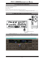
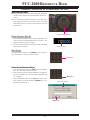
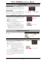
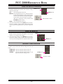
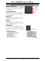
FT-2000 AND COMPUTER INTERCONNECTIONS
“PCC-2000” PERSONAL COMPUTER CONTROLLER WINDOW
PCC-2000 SYSTEM COMPONENTS
IBM
®
PC / compatible Computer with Microsoft
®
Windows
®
2000, XP, or Vista
30 MB of available Hard Disk space
256 MB or more RAM
RS-232C port
1024 x 768 color display with 256-bit color support on the video card
RS-232C “Straight” Cable, DB9-pin Female to DB9-pin Female (Or, USB to RS-232C Adapter Cable
Ú
).
Ú
: SomeUSB to RS-232C Adapter Cable does not function normally.
COM
C
A
T
RS-232C “Straight” Cable
If you double-click the left mouse button on each knob or switch of the following illustration, jump to the detailed page of
the selected knob or switch.

PCC-2000 REFERENCE BOOK
- 4 -
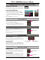
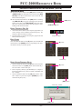
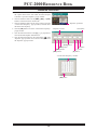
OPENING/CLOSING THE PCC-2000 CONTROLLER PROGRAM
OPENING THE PCC-2000 PROGRAM
Double click the left mouse button on the “PCC-2000” icon. The
“Vertex Standard” logo will appear for three seconds; afterwards
the “PCC-2000” Personal Computer Controller will be opened.
CLOSING THE PCC-2000 PROGRAM
To close the “PCC-2000” Personal Computer Controller:
Click the left mouse button on the Close Button “ ” on the
“PCC-2000” Personal Computer Controller.
Click the left mouse button on the “Exit” parameter in the
“File” menu on the “PCC-2000” Personal Computer Con-
troller.
Press the
[
ESC
]
button on the keyboard.
DATA CONNECTION
Click the left mouse button on the
[
COM
]
button of the “PCC-
2000” Personal Computer Controller to enable computer con-
trol. The yellow indicator will glow.
Click the left mouse button on the
[
COM
]
button of the “PCC-
2000” Personal Computer Controller again to disable com-
puter control. The yellow indicator will go out.
SWITCHING POWER ON/OFF OF THE FT-2000
Click the left mouse button on the
[
ON/OFF
]
button of the “PCC-
2000” Personal Computer Controller to turn the transceiver “On”
and “Off.”
Note: the transceiver’s rear panel Power switch must already have
been turned on manually.
AF GAIN CONTROL
MAIN BAND
(
VFO-A
)
Click the left mouse button on the main
[
AF GAIN
]
knob (this
turns the color of the “AF GAIN” image yellow), then turn the
mouse scroll or press the left/right buttons to adjust the audio for
a comfortable listening level.
SUB BAND
(
VFO-B
)
Click the left mouse button on the sub
[
AF GAIN
]
knob (this
turns the color of the sub “AF GAIN” image yellow), then turn
the mouse scroll or press the left/right buttons to adjust the audio
for a comfortable listening level.
SQL LEVEL CONTROL
MAIN BAND
(
VFO-A
)
Click the left mouse button on the
[
SQL
]
knob (this turns the
color of the “SQL” image yellow), then turn the mouse scroll, or
press the left/right buttons, to adjust the squelch threshold level.
SUB BAND
(
VFO-B
)
Click the left mouse button on the sub
[
SQL
]
knob (this turns the
color of the sub “SQL” image yellow), then turn the mouse scroll,
or press the left/right buttons, to adjust the squelch threshold level.
[
COM
]
button
[
ON/OFF
]
button
Main
[
AF GAIN
]
knobSub
[
AF GAIN
]
knob
Main
[
SQL
]
knob
Sub
[
SQL
]
knob
“EXIT” parameter
“PCC-2000” icon
Close button

PCC-2000 REFERENCE BOOK
- 5 -
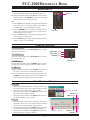
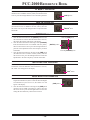
FREQUENCY NAVIGATION ON THE MAIN BAND
(
VFO-A
)
MAIN TUNING DIAL KNOB
Bring the mouse cursor to the Main Tuning Dial knob, then
turn the mouse scroll to tune the Main Band (VFO-A) fre-
quency.
Press and hold in the left mouse button on the edge of the
Main Tuning Dial knob, then rotate the mouse, to tune the
Main Band (VFO-A) frequency while holding in the left
mouse button.
Main Tuning Dial knob
DIRECT FREQUENCY DIGIT SET
1. Click the left mouse button on the frequency digit which you
wish to change on the Main Band (VFO-A) frequency. The
frequency digit will change to Orange.
2. Turn the mouse scroll to tune the frequency digit of the Main
Band (VFO-A) frequency.
BAND CHANGE
Click the left mouse button on the
[
BAND
]
button correspond-
ing to the Amateur on which you wish to operate.
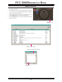
DIRECT KEYPAD FREQUENCY ENTRY
1. Click the left mouse button on the
[
ENT
]
button of the BAND
keys. The “VFO SET” window will open.
2. Enter a frequency directly from the BAND keys or computer’s
keyboard. Available entry values are 30000 - 60000000 (300
Hz - 60 MHz).
3. Click the left mouse button on the
[
OK
]
button of the “VFO
SET” window or press the computer’s
[
ENTER
]
key to ter-
minate the frequency entry.
Frequency Digit
BAND keys
[
ENT
]
button
“VFO SET” window
[
OK
]
button

PCC-2000 REFERENCE BOOK
- 6 -
FREQUENCY NAVIGATION ON THE SUB BAND
(
VFO-B
)
[
SUB VFO-B
]
KNOB
Click the left mouse button on the
[
A/B
]
button to enable the
[
SUB VFO-B
]
knob. Bring the mouse cursor to the
[
SUB
VFO-B
]
knob, then turn the mouse scroll to tune the Sub
Band (VFO-B) frequency.
Click the left mouse button on the
[
A/B
]
button to enabling
the
[
SUB VFO-B
]
knob. Press and hold in the left mouse
button on the edge of the
[
SUB VFO-B
]
knob, then rotate
the mouse, to tune the Sub Band (VFO-B) frequency while
holding in the left mouse button.
DIRECT FREQUENCY DIGIT SET
1. Click the left mouse button on the frequency digit which you
wish to change on the Sub Band (VFO-B) frequency. The
frequency digit will change to Orange.
2. Turn the mouse scroll to tune the frequency digit of the Sub
Band (VFO-B) frequency.
BAND CHANGE
Click the left mouse button on the
[
B
]
button, then click the left
mouse button on the
[
BAND
]
button corresponding to the Ama-
teur band on which you wish to operate.
[
SUB VFO-B
]
knob
[
A/B
]
button
Frequency Digit
DIRECT KEYPAD FREQUENCY ENTRY
1. Click the left mouse button on the
[
B
]
button, then click the
left mouse button on the
[
ENT
]
button of the BAND keys.
The “VFO SET” window will open.
2. Enter a frequency directly by the BAND keys or computer’s
keyboard. Available entry values are 30000 - 60000000 (300
Hz - 60 MHz).
3. Click the left mouse button on the
[
OK
]
button of the “VFO
SET” window or press the computer’s
[
ENTER
]
key to ter-
minate the frequency entry.
[
B
]
button
BAND keys
[
B
]
button
[
ENT
]
button
“VFO SET” window
[
OK
]
button

PCC-2000 REFERENCE BOOK
- 7 -
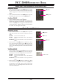
MODE SWITCH
Click the left mouse button on the
[
MODE
]
button to select
the desired operating mode for the Main band (VFO-A).
Click the left mouse button on the
[
B
]
button, then click the
left mouse button on the
[
MODE
]
button to select the desired
operating mode for the Sub band (VFO-B).
Note:
Click the
[
B
]
button repeatedly to toggle the operating mode
between the “CW-U” and “CW-L” selections (CW with Up-
per Sideband or Lower Sideband BFO injection).
Click the
[
AM/FM
]
button to toggle the operating mode be-
tween “AM” (inside of the button glows red) and “FM” (in-
side of the button glows orange).
Click the
[
RTTY
]
button to toggle the operating mode be-
tween “RTTY-U” and “RTTY-L.”
Click the
[
PKT
]
button to toggle the operating mode between
“PKT-U,” “PKT-L,” and “PKT-FM.”
CLARIFIER OPERATION
RX CLAR SWITCH
Click the left mouse button on the
[
RX CLAR
]
button to turn the
RX Clarifier on and off.
TX CLAR SWITCH
Click the left mouse button on the
[
TX CLAR
]
button to turn the
TX Clarifier on and off.
CLEAR SWITCH
Click the left mouse button on the
[
CLEAR
]
button to clear the
Clarifier offset frequency (thereby setting the offset to “Zero”).
CLAR KNOB
Click the left mouse button on the
[
CLAR
]
knob, then turn
the mouse scroll to tune the Clarifier offset frequency.
Press and hold in the left mouse button on the edge of the
[
CLAR
]
knob, then rotate the mouse to tune the Clarifier off-
set frequency while holding in the left mouse button.
AUDIO PLAYBACK FEATURE
RECORDING
1. Click the left mouse button on the “Playback” parameter in
the “Option” menu on the “PCC-2000” Personal Computer
Controller to open the “Playback” pop-up window.
2. Click the left mouse button on the
[
REC
]
button of the Audio
Playback feature to initiate recording.
3. Click the left mouse button on the
[
STOP
]
button of the Au-
dio Playback feature to stop recording.
PLAYBACK
1. Click the left mouse button on the “Playback” parameter in
the “Option” menu on the “PCC-2000” Personal Computer
Controller to open the “Playback” pop-up window.
2. Click the left mouse button on the
[
PLAY
]
button of the Audio
Playback feature to begin playback of the recorded audio.
3. Click the left mouse button on the
[
STOP
]
button of the Au-
dio Playback feature to stop the playback.
[
B
]
button
MODE key’s
[
CLAR
]
knob
[
RX CLAR
]
button
[
TX CLAR
]
button
[
CLEAR
]
button
[
STOP
]
button
[
PLAY
]
button
[
STOP
]
button
[
REC
]
button
“Playback” parameter
“Playback” window

PCC-2000 REFERENCE BOOK
- 8 -
VOICE MEMORY FEATURE
RECORDING
1. Click the left mouse button on the “Playback” parameter in
the “Option” menu on the “PCC-2000” Personal Computer
Controller to open the “Playback” pop-up window.
2. Click the left mouse button on the desired Memory Channel
button (REC
[
Ch-1
]
~ REC
[
Ch-5
]
) for the Voice Memory
feature to initiate recording.
3. Click the left mouse button on the
[
STOP
]
button for the
Voice Memory feature to stop recording.
PLAYBACK
1. Click the left mouse button on the “Playback” parameter in
the “Option” menu on the “PCC-2000” Personal Computer
Controller to open the “Playback” pop-up window.
2. Click the left mouse button on the desired Memory Channel
button (PLAY
[
Ch-1
]
~ PLAY
[
Ch-5
]
) for the Voice Memory
feature to begin playback of the recorded audio.
3. Click the left mouse button on the
[
STOP
]
button for the
Voice Memory feature to stop the playback.
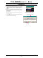
ANTENNA SELECTION
Click the left mouse button on the
[
ANTENNA 1/2
]
button to
open the “ANT” pop-up window, then select the antenna on which
you wish to operate.
To use the RX ANT, repeatedly click the left mouse button on the
[
ANTENNA RX
]
button to turn the RX antenna on and off. When
the RX antenna is selected, the “RX” icon will appear in the dis-
play.
IPO
(
INTERCEPT POINT OPTIMIZATION
)
Click the left mouse button on the
[
IPO
]
button to open the “IPO”
pop-up window, then select the front-end system you wish to
use.
AMP1: low-distortion amplifier.
AMP2: 2-stage low-distortion amplifier.
IPO: bypasses the front end RF amplifier.
ATT
(
ATTENUATOR
)
Click the left mouse button on the
[
ATT
]
button to open the “ATT”
pop-up window, then select the attenuation level which you wish
to utilize.
PLAY
[
Ch-x
]
button
[
PLAY
]
button
[
STOP
]
button
REC
[
Ch-x
]
button
[
RX
]
button
[
ANTENNA 1/2
]
button
[
IPO
]
button
“IPO” window
[
ATT
]
button
“ATT” window
“Playback” parameter
“Playback” window

PCC-2000 REFERENCE BOOK
- 9 -
RF GAIN CONTROL
MAIN BAND
(
VFO-A
)
Click the left mouse button on the main
[
RF GAIN
]
knob (the
indication color of “RF GAIN” will turn yellow), then turn the
mouse scroll or press the left/right buttons to adjust the RF gain.
SUB BAND
(
VFO-B
)
Click the left mouse button on the sub
[
RF GAIN
]
knob (the
indication color of “RF GAIN” will turn yellow), then turn the
mouse scroll or press the left/right buttons to adjust the RF gain.
VRF
(
VARIABLE RF FRONT-END FILTER
)
OPERATION
1. Click the left mouse button on the
[
VRF
]
button to open the
“VRF” pop-up window, then select the configuration you wish
to use.
VRF OFF: Turns the VRF filter off.
VRF ON: Turns the VRF filter on.
DEFAULT: Moves the passband of the VRF filter to the cen-
ter of the current amateur band.
2. When you have set the
[
VRF
]
button to “VRF ON:”
Bring the mouse cursor to the
[
VRF
]
knob, then turn the
mouse scroll to move the passband of the VRF filter.
Press and hold in the left mouse button on the edge of the
[
VRF
]
knob, then rotate the mouse to move the passband
of the VRF filter while holding the left mouse button.
ROOFING FILTER SELECTION
Click the left mouse button on the
[
R.FLT
]
button to open the
“Roofing Filter” pop-up window, then select the bandwidth you
wish to utilize.
CONTOUR FILTER / APF
(
AUDIO PEAK FILTER
)
O
PERATION
1. Click the left mouse button on the
[
CONT
]
button to open
the “Contour/APF” pop-up window, then select the configu-
ration you wish to use.
OFF: Turns the Contour filter/APF both off.
CONTOUR: Turns the Contour filter on. The Contour filter
characteristic will appear in the display
APF: Turns the APF (Audio Peak Filter) filter on.
The APF is activated only with a CW mode.
The “CONTOUR” indication on the display
will change to “APF”.
2. When the Contour filter is set to on, click the left mouse but-
ton on the edge of the
[
CONTOUR
]
knob (the indication
color of “CONTOUR” will turn yellow), then turn the mouse
scroll or press the left/right buttons to adjust the center fre-
quency of the Contour filter (There is no adjustmet knob as-
sociated with the APF).
Main
[
RF GAIN
]
knobSub
[
RF GAIN
]
knob
[
VRF
]
knob
[
VRF
]
button
“VRF” window
[
R.FLT
]
button
“R.FLT” window
[
CONTOUR
]
knob
[
CONT
]
button
“Contour/APF” window

PCC-2000 REFERENCE BOOK
- 10 -
[
SHIFT
]
knob
IF SHIFT OPERATION
Click the left mouse button on the edge of the
[
SHIFT
]
knob (the
indication color of “SHIFT” will turn yellow), then turn the mouse
scroll or press the left/right buttons to move the filter passband.
WIDTH OPERATION
Click the left mouse button on the edge of the
[
WIDTH
]
knob
(the indication color of “WIDTH” will turn yellow), then turn
the mouse scroll or press the left/right buttons to adjust the filter
bandwidth.
NOTCH OPERATION
1. Click the left mouse button on the
[
NOTCH
]
button to turn
the Notch filter on and off. When the Notch filter is set to on,
the Notch characteristic will appear in the display.
2. Click the left mouse button on the edge of the
[
COARSE
]
knob (the indication color of “COARSE” will turn yellow),
then turn the mouse scroll or press the left/right buttons to
perform coarse adjustment of the center frequency of the IF
Notch filter.
3. Click the left mouse button on the edge of the
[
FINE
]
knob
(the indication color of “FINE” will turn yellow), then turn
the mouse scroll or press the left/right buttons to make fine
adjustments to the center frequency of the IF Notch filter.
AUTO NOTCH OPERATION
Click the left mouse button on the
[
DNF
]
button to turn the Auto
Notch filter on and off. When the Auto Notch filter is set to on,
the “DNF” icon will appear in the display.
NOISE REDUCTION OPERATION
1. Click the left mouse button on the
[
DNR
]
button to turn the
Digital Noise Reduction system on and off. When the Digital
Noise Reduction system is set to on, the “DNR” icon will
appear in the display.
2. Click the left mouse button on the edge of the
[
DNR
]
knob
(the font color of “DNR” will change to yellow), then turn
the mouse scroll or press the left/right buttons to select the
setting that most effectively reduces the noise level.
[
WIDTH
]
knob
NOTCH
[
FINE
]
knob
[
NOTCH
]
button
NOTCH
[
COARSE
]
knob
[
DNF
]
button
[
DNR
]
button

PCC-2000 REFERENCE BOOK
- 11 -
NAR
(
ONE-TOUCH NARROW IF FILTER SELECTION
)
MAIN BAND
(
VFO-A
)
1. Click the left mouse button on the
[
NAR
]
button to engage
the preset “Narrow” IF filter selection. When the narrow band-
width is engaged, the “NAR” indication will appear in the
display.
2. Click the left mouse button on the
[
NAR
]
button again; the
bandwidth will revert to that set by the
[
WIDTH
]
knob.
SUB BAND
(
VFO-B
)
1. Click the left mouse button on the
[
B
]
button.
2. Within five seconds of clicking the
[
B
]
button (while the im-
bedded orange indicator is illuminated), click the left mouse
button on the
[
NAR
]
button to toggle the bandwidth between
“Wide” and “Narrow.” When the “Narrow” option is selected,
the “NAR” icon will appear in the display.
NOISE BLANKER OPERATION
MAIN BAND
(
VFO-A
)
1. Click the left mouse button on the
[
NB
]
button to open the
“NB” pop-up window, then select the configuration you wish
to use.
NB OFF: Turns the Noise Blanker off.
NB ON: Turns the Noise Blanker on (for short-duration
pulses).
NB-W ON: Turns the Noise Blanker on (for longer-duration
pulses).
2. When you have set the
[
NB
]
button to “NB ON” or “NB-W
ON,” click the left mouse button on the
[
NB
]
knob (the indi-
cation color of “NB” will turn yellow), then turn the mouse
scroll or press the left/right buttons to select the noise blank-
ing level.
SUB BAND
(
VFO-B
)
1. Click the left mouse button on the
[
B
]
button, then click the
left mouse button on the
[
NB
]
button to open the “NB” pop-
up window; now select the configuration you wish to use.
NB OFF: Turns the Noise Blanker off.
NB ON: Turns the Noise Blanker on (for short-duration
pulses).
NB-W ON: Turns the Noise Blanker on (for longer-duration
pulses).
2. When you have set the
[
NB
]
button to “NB ON” or “NB-W
ON,” left-click on the
[
B
]
button followed by the
[
NB
]
knob
(the indication color of “NB” will turn yellow), then turn the
mouse scroll or press the left/right buttons to select the de-
sired noise blanking level.
[
B
]
button
[
NAR
]
button
[
NB
]
button
[
NB
]
knob
[
B
]
button
“NB” window

PCC-2000 REFERENCE BOOK
- 12 -
AGC
SUB BAND
(
VFO-B
)
Click the left mouse button on the
[
AGC
]
button to open the
“AGC” pop-up window, then select the desired receiver-recov-
ery time.
SUB BAND
(
VFO-B
)
Click the left mouse button on the
[
B
]
button, and then click the
left mouse button on the
[
AGC
]
button to open the “AGC” pop-
up window; now select the desired receiver-recovery time.
LOCK FEATURE
Click the left mouse button on the
[
LOCK
]
button to turn the
Main Tuning Dial knob Lock “on” and “off.” When the Main
Tuning Dial knob is set to be locked, the “LOCK” icon will ap-
pear in the display.
VOX OPERATION
1. Click the left mouse button on the
[
VOX
]
button to turn the
VOX circuit on and off. When the VOX circuit is set to on,
the inside of the button glows red.
2. Click the left mouse button on the
[
VOX
]
knob (the indica-
tion color of “VOX” will turn yellow), then turn the mouse
scroll or press the left/right buttons to adjust the VOX gain.
3. Click the left mouse button on the
[
DELAY
]
knob (the indi-
cation color of “DELAY” will turn yellow), then turn the
mouse scroll or press the left/right buttons to adjust the hang
time of the VOX circuit.
[
AGC
]
button
[
B
]
button
“AGC” window
[
LOCK
]
button
[
VOX
]
button
[
VOX
]
knob
[
DELAY
]
knob

PCC-2000 REFERENCE BOOK
- 13 -
USING THE SPEECH PROCESSOR
1. Click the left mouse button on the
[
PROC
]
button to open
the “PROCESSOR” pop-up window, then select the configu-
ration you wish to use.
OFF: Turns the Speech Processor off.
MIC-EQ: Turns the Speech Processor on, with the Paramet-
ric Microphone Equalizer. You may adjust the char-
acteristic of the Parametric Microphone Equalizer
by the “Prmtrc” menu. See page 15 for details.
Note: This configuration is only selected on the
FT-2000D (200 W version).
PROC: Turns the Speech Processor on.
2. Click the left mouse button on the
[
PROC
]
knob (the indica-
tion color of “PROC” will turn yellow), then turn the mouse
scroll or press the left/right buttons to select the Compression
level.
USING THE MONITOR
1. Click the left mouse button on the
[
MONI
]
button to turn the
Monitor circuit on and off. When the Monitor is set to on, the
“MONI” icon will appear in the display.
2. Click the left mouse button on the
[
MONI
]
knob (the indica-
tion color of “MONI” will turn yellow), then turn the mouse
scroll or press the left/right buttons to adjust the Monitor level.
ANTENNA TUNER OPERATION
Click the left mouse button on the
[
TUNE
]
button to open the
“TUNER” pop-up window, then select the configuration you wish
to use.
TUNER OFF: Turns the Automatic Antenna Tuner off.
TUNER ON: Turns the Automatic Antenna Tuner on.
TUNING: Turns the Automatic Antenna Tuner on, and
begins the automatic tuning process.
[
PROC
]
knob
[
PROC
]
button
“PROCESSOR” window
[
MONI
]
knob
[
MONI
]
button
[
TUNE
]
button
“TUNER” window

PCC-2000 REFERENCE BOOK
- 14 -
REPEATER OPERATION
1. Click the left mouse button on the “Repeater” parameter in
the “Option” menu on the “PCC-2000” Personal Computer
Controller to open the “Repeater” pop-up window.
2. Click the left mouse button on the
[
ENC
]
,
[
SQL
]
, or
[
OFF
]
button to select the desired CTCSS mode.
3. Click the left mouse button on the “Freq” button to open the
“CTCSS Tone Frequency” pop-up window, and then select
the desired tone frequency.
4. Click the
[
OK
]
button to close the “CTCSS Tone Frequency”
pop-up window.
5. Click the left mouse button on the
[
S
]
,
[
–
]
, or
[
+
]
button to
select the desired Repeater Shift Direction.
6. Click the left mouse button on the Close Button “ ” on the
“Repeater” pop-up window to save the new setting and close
the “Repeater” pop-up window.
Close button
[
+
]
button
[
Freq
]
button
[
SQL
]
button
[
ENC
]
button
[
OFF
]
button
[
–
]
button
[
S
]
button
[
OK
]
button
“CTCSS Tone Frequency” window
“Repeater” window
“Repeater” parameter

PCC-2000 REFERENCE BOOK
- 15 -
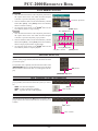
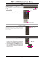
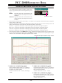
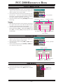
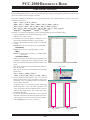
PARAMETRIC MICROPHONE EQUALIZER ADJUSTMENT
1. Click the left mouse button on the “Prmtrc” menu on the
“PCC-2000” Personal Computer Controller to open the “Para-
metric” pop-up window, then select the configuration you wish
to use.
Prmtric: Adjust the characteristic of the Parametric Mi-
crophone Equalizer when the Speach Processor
is disabled.
P-Prmtric: Adjust the characteristic of the Parametric Mi-
crophone Equalizer when the Speach Processor
is enabled.
2. When click the left mouse button on the “Prmtrc” or “P-Prmtrc” menu, open the “Parametric Microphone Equalizer
Graph” window on the monitor.
3. Adjust the characteristic of the Parametric Microphone Equalizer using the each arrow switch. You may observe the
setting of the characteristic of the Parametric Microphone Equalizer on the monitor.
Red Curve: Appears the characteristic of the lower range for the parametric microphone equalizer.
Blue Curve: Appears the characteristic of the middle range for the parametric microphone equalizer.
Green Curve: Appears the characteristic of the high range for the parametric microphone equalizer.
Black Curve: Appears the characteristic of the overall range for the parametric microphone equalizer.
4. Click the left mouse button on the
[
APPLI
]
button on the “Parametric Microphone Equalizer Graph” window to save
the new setting and click the left mouse button on the
[
EXIT
]
button on the “Parametric Microphone Equalizer Graph”
window to close the “Parametric Microphone Equalizer Graph” window.
“Parametric” window
c
PRMTRC EQ1
(
P-PRMTRC EQ1
)
FREQ
Click the left mouse button on the
[
Å
]
/
[
Æ
]
button to
selects the center frequency of the lower range for the
parametric microphone equalizer.
Available selections are 100 ~ 700 Hz (100 Hz/step)
or OFF.
d
PRMTRC EQ1
(
P-PRMTRC EQ1
)
LEVEL
Click the left mouse button on the
[
Ç
]
/
[
È
]
button to
adjusts the equalizer gain of the low range of the para-
metric microphone equalizer.
Available selections are –20 dB ~ +10 dB.
e
PRMTRC EQ1
(
P-PRMTRC EQ1
)
BWTH
Click the left mouse button on the
[
ÆÅ
]
/
[
ÅÆ
]
but-
ton to adjusts the Q-factor of the low range of the para-
metric microphone equalizer.
Available selections are 1 ~ 10.
“Parametric Microphone Equalizer Graph” window
k
c
d
e
f
g
h
i
j

PCC-2000 REFERENCE BOOK
- 16 -
KEYER OPERATION
1. Click the left mouse button on the
[
KEYER
]
button to turn
the CW Keyer on and off. When the CW Keyer is set to on,
the “KEYER” icon will appear in the display.
2. Click the left mouse button on the
[
SPEED
]
knob (the indi-
cation color of “SPEED” will turn yellow), then turn the mouse
scroll or press the left/right buttons to set the desired keying
speed.
3. Click the left mouse button on the
[
PITCH
]
knob (the indica-
tion color of “PITCH” will turn yellow), then turn the mouse
scroll or press the left/right buttons to set the desired CW
tone pitch.
4. Click the left mouse button on the
[
BK-IN
]
button to turn the
CW Break-in circuit on and off. When the CW Break-in cir-
cuit is set to on, the “BK-IN” icon will appear in the display.
5. Click the left mouse button on the
[
DELAY
]
knob (the indi-
cation color of “DELAY” will turn yellow), then turn the
mouse scroll or press the left/right buttons to adjust the CW
delay time.
[
DELAY
]
knob
[
KEYER
]
button
[
BK-IN
]
button
[
PITCH
]
knob
[
SPEED
]
knob
f
PRMTRC EQ2
(
P-PRMTRC EQ2
)
FREQ
Click the left mouse button on the
[
Å
]
/
[
Æ
]
button to
selects the center frequency of the middle range for
the parametric microphone equalizer.
Available selections are 700 ~ 1500 Hz (100 Hz/step)
or OFF.
g
PRMTRC EQ2
(
P-PRMTRC EQ2
)
LEVEL
Click the left mouse button on the
[
Ç
]
/
[
È
]
button to
adjusts the equalizer gain of the middle range of the
parametric microphone equalizer.
Available selections are –20 dB ~ +10 dB.
h
PRMTRC EQ2
(
P-PRMTRC EQ2
)
BWTH
Click the left mouse button on the
[
ÆÅ
]
/
[
ÅÆ
]
but-
ton to adjusts the Q-factor of the middle range of the
parametric microphone equalizer.
Available selections are 1 ~ 10.
i
PRMTRC EQ3
(
P-PRMTRC EQ3
)
FREQ
Click the left mouse button on the
[
Å
]
/
[
Æ
]
button to
selects the center frequency of the high range for the
parametric microphone equalizer.
Available selections are 1500 ~ 3200 Hz (100 Hz/step)
or OFF.
j
PRMTRC EQ3
(
P-PRMTRC EQ3
)
LEVEL
Click the left mouse button on the
[
Ç
]
/
[
È
]
button to
adjusts the equalizer gain of the high range of the para-
metric microphone equalizer.
Available selections are –20 dB ~ +10 dB.
k
PRMTRC EQ3
(
P-PRMTRC EQ3
)
BWTH
Click the left mouse button on the
[
ÆÅ
]
/
[
ÅÆ
]
but-
ton to adjusts the Q-factor of the high range of the
parametric microphone equalizer.
Available selections are 1 ~ 10.
[
EXIT
]
Button
Click the left mouse button on this button to close the
“Repeater” pop-up window.
[
CANCEL
]
Button
Click the left mouse button on this button to save the
new setting.
[
APPLI
]
Button
Click the left mouse button on this button to save the
new setting.
[
FILE SAVE
]
Button
Click the left mouse button on this button to open the
“File Save” pop-up window and save the new setting
to your computer (pef file).
[
FILE LOAD
]
Button
Click the left mouse button this button to open the
“File Load” pop-up window and load the previously
stored setting.
PARAMETRIC MICROPHONE EQUALIZER ADJUSTMENT

PCC-2000 REFERENCE BOOK
- 17 -
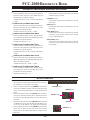
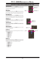
CONTEST MEMORY KEYER
TEXT MEMORY STORAGE
1. Click the left mouse button on the “CW” parameter in the
“Option” menu on the “PCC-2000” Personal Computer Con-
troller to open the “CW” pop-up window.
2. Click the left mouse button on the desired Text Memory Chan-
nel (“Text Ch-1” ~ “Text Ch-5”), then enter the message from
the computer’s keyboard. Remember to add the “}” character
at the end to signify the termination of the message.
3. Click the left mouse button on the
[
CH-x WR
]
button to save
the message.
PLAYBACK
1. Click the left mouse button on the “Playback” parameter in
the “Option” menu on the “PCC-2000” Personal Computer
Controller to open the “Playback” pop-up window.
2. Click the left mouse button on the desired Memory Channel
button (Message Play
[
Ch-1
]
~ Message Play
[
Ch-5
]
or Text
Play
[
Ch-1
]
~ Text Play
[
Ch-5
]
) to begin playback of the
recorded audio.
ROTATOR CONTROL
1. Click the left mouse button on the “Rotator” parameter in the
“Option” menu on the “PCC-2000” Personal Computer Con-
troller to open the “Rotator” pop-up window.
2. Click the left mouse button on the
[
CCW
]
or
[
CW
]
button to
rotate the antenna.
3. Click the left mouse button on the
[
SLOW
]
or
[
FAST
]
but-
ton to adjust the rotation speed.
“Message Play” button’s “Text Play” button’s
[
CH-x WR
]
buttonText Memory Channel
QMB MEMORY
Click the left mouse button on the
[
STO
]
button to write the
current main band (VFO-A) data to the QMB memory.
Click the left mouse button on the
[
RCL
]
button to recall the
QMB memory.
[
FAST
]
button
[
SLOW
]
button
[
CW
]
button
[
CCW
]
button
[
STO
]
button
[
RCL
]
button
“Rotator” window
“CW” window
“CW” parameter
“Rotator” parameter

PCC-2000 REFERENCE BOOK
- 18 -
OPERATION OF MISCELLANEOUS KNOBS AND BUTTONS
[
METER
]
KNOB
Click the left mouse button on the
[
METER
]
knob, then turn the
mouse scroll or press the left/right buttons to select the function
of the meter during transmission.
[
MIC
]
K
NOB
Click the left mouse button on the
[
MIC
]
knob (the indication
color of “MIC” will turn yellow), then turn the mouse scroll or
press the left/right buttons to select the Microphone gain level.
[
RF PWR
]
KNOB
Click the left mouse button on the
[
RF PWR
]
knob (the indica-
tion color of “RF PWR” will turn yellow), then turn the mouse
scroll or press the left/right buttons to set the desired output power.
[
DIM
]
BUTTON
Click the left mouse button on the
[
DIM
]
button to toggle the
illumination level of the Meter/Display between “Hi” and “Low.”
[
MOX
]
BUTTON
Click the left mouse button on the
[
MOX
]
button to engage trans-
mission. When the MOX circuit is set to on, the inside of the
button glows red.
[
SPOT
]
BUTTON
Click the left mouse button on the
[
SPOT
]
button to turn on the
CW receiver spotting tone.
[
A
]
BUTTON
When this button glows red, the following buttons are active on
the Main Band (VFO-A).
[
MODE
]
Button
[
BAND
]
Button
[
NAR
]
Button
[
AGC
]
Button
[
NB
]
Button
[
NB
]
Knob
[
B
]
BUTTON
Click the left mouse button on the
[
B
]
button to turn the button
orange for five seconds. When this button glows orange, the fol-
lowing buttons are active on the Sub Band (VFO-B).
[
MODE
]
Button
[
BAND
]
Button
[
NAR
]
Button
[
AGC
]
Button
[
NB
]
Button
[
NB
]
Knob
[
MIC
]
knob
[
RF PWR
]
knob
[
METER
]
knob
[
DIM
]
button
[
MOX
]
button
[
SPOT
]
button
[
B
]
button
[
A
]
button

PCC-2000 REFERENCE BOOK
- 19 -
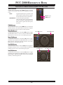
[
SPLIT
]
BUTTON
Click the left mouse button on the
[
SPLIT
]
button to open the
“SPLIT” pop-up window, then select the configuration you wish
to use.
SPLIT: Toggle the Split Frequency operation on and
off. The VFO-A will be used for reception,
and VFO-B will be used for transmssion.
QUICK SPLIT: Activates the Quick Split feature.
(Sub (VFO-B) register will automatically
be set to a frequency 5 kHz higher than the
Main (VFO-A) register with same operat-
ing mode.)
[
TXW
]
BUTTON
Click the left mouse button on the
[
TXW
]
button to monitor the
transmit frequency when split frequency operation is engaged.
Release the mouse button to return to normal operation.
MAIN
[
RX
]
BUTTON
Click the left mouse button on the Main
[
RX
]
button to toggle
the Main Band (VFO-A) receiver on and off. When the Main
Band (VFO-A) receiver is set to on, the button glows green.
MAIN
[
TX
]
BUTTON
Click the left mouse button on the Main
[
TX
]
button to toggle
transmitter control between the “Main Band (VFO-A)” and “Sub
Band (VFO-B).” When the transmitter control is set to “Main
Band (VFO-A),” this button glows red.
SUB
[
RX
]
BUTTON
Click the left mouse button on the Sub
[
RX
]
button to toggle the
Sub Band (VFO-B) receiver on and off. When the Sub Band
(VFO-B) receiver is set to on, this button glows green.
SUB
[
TX
]
BUTTON
Click the left mouse button on the Sub
[
TX
]
button to toggle
transmitter control between the “Main Band (VFO-A)” and “Sub
Band (VFO-B).” When the transmitter control is set to “Sub Band
(VFO-B),” this button glows red.
OPERATION OF MISCELLANEOUS KNOBS AND BUTTONS
[
SPLIT
]
button
[
TXW
]
button
Main
[
RX
]
button Main
[
TX
]
button
Sub
[
RX
]
button Sub
[
TX
]
button

PCC-2000 REFERENCE BOOK
- 20 -
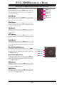
[
FAST
]
BUTTON
Click the left mouse button on the
[
FAST
]
button to toggle the
tuning rate of the Main Tuning Dial knob between “Fast” and
“Slow.” When the tuning rate is set to “Fast,” the “FAST” icon
will appear in the display.
[
A
X
B
]
BUTTON
Click the left mouse button on the
[
A
X
B
]
button to transfer data
from the Main band (VFO-A) frequency (or a recalled memory
channel) to the Sub band (VFO-B).
[
A
X
W
B
]
BUTTON
Click the left mouse button on the
[
A
X
W
B
]
button to exchange the
contents of the Main band (VFO-A) (or a recalled memory chan-
nel) and the Sub band (VFO-B).
[
V/M
]
BUTTON
Click the left mouse button on the
[
V/M
]
button to toggle the
Main band (VFO-A) receiver operation between the memory sys-
tem and the VFO.
[
M
X
A
]
BUTTON
Click the left mouse button on the
[
M
X
A
]
button to copy the
data from the currently-selected memory to the Main VFO (VFO-
A).
[
A
X
M
]
BUTTON
Click the left mouse button on the
[
A
X
M
]
button to copy the
current operating data from the Main band (VFO-A) into the
currently selected memory channel, overwriting any previous data
stored there.
MAIN
(
VFO-A
)
[
BAND
]
BUTTON
Clicking the left mouse button on the Main (VFO-A)
[
BAND
]
button (the inside of the button will glow red) allows you to se-
lect the Main (VFO-A) operating band (Amateur bands) using
the
[
SUB VFO-B
]
knob.
MAIN
(
VFO-A
)
[
MHZ
]
BUTTON
Clicking the left mouse button on the Main (VFO-A)
[
MHz
]
but-
ton (the inside of the button will glow red) allows you to turn the
Main (VFO-A) frequency down or up in 1 MHz increments, us-
ing the
[
SUB VFO-B
]
knob.
[
GRP
]
BUTTON
Clicking the left mouse button on the
[
GRP
]
button (the inside
of the button will glow red) allows you to select the memory
group using the
[
SUB VFO-B
]
knob.
[
MCH
]
BUTTON
Clicking the left mouse button on the
[
MCH
]
button (the inside
of the button will glow red) allows you to select the memory
channel using the
[
SUB VFO-B
]
knob.
OPERATION OF MISCELLANEOUS KNOBS AND BUTTONS
[
FAST
]
button
[
A
X
B
]
button
[
A
X
W
B
]
button
[
V/M
]
button
[
M
X
A
]
button
[
A
X
M
]
button
Main
[
BAND
]
button
Main
[
MHz
]
button
[
GRP
]
button
[
MCH
]
button
La pagina si sta caricando...
La pagina si sta caricando...
La pagina si sta caricando...
La pagina si sta caricando...
La pagina si sta caricando...
La pagina si sta caricando...
-
 1
1
-
 2
2
-
 3
3
-
 4
4
-
 5
5
-
 6
6
-
 7
7
-
 8
8
-
 9
9
-
 10
10
-
 11
11
-
 12
12
-
 13
13
-
 14
14
-
 15
15
-
 16
16
-
 17
17
-
 18
18
-
 19
19
-
 20
20
-
 21
21
-
 22
22
-
 23
23
-
 24
24
-
 25
25
-
 26
26


in altre lingue
- English: YAESU PCC-2000
Altri documenti
-
Motorola MICOM 2E User Instructions
-
ICOM E Manuale del proprietario
-
Yamaha V2 Manuale del proprietario
-
Yamaha V3 Manuale del proprietario
-
-
-
-
-
Midland M-88 CB-Funkgerät Manuale del proprietario
-
Baofeng UV-3R Manuale utente