
Istruzione
047U59428 04/2023
K470WX021 (K470W)
Testa wireless per radiatore
Istruzioni per l'uso e garanzia
Si prega di leggere le istruzioni per l’uso prima
dell’applicazione del regolatore a risparmio energetico.
Conservare la documentazione per future consultazioni
e consegnarla assieme al dispositivo in caso di cessione
del prodotto a terzi.
Fornitura
1 testa wireless K470WX021
1 istruzioni per l'uso
1 ghiera adattatore per valvole termostatizzabili
Giacomini Clip-Clap (ad eccezione delle valvole serie
DB)
AVVERTENZE.
La testa K470WX021 è prevista per l’utilizzo in edici.
Utilizzare K470WX021 solo come descritto nelle istruzioni per l’uso.
K470WX021 deve essere utilizzata soltanto in un luogo asciutto, privo
di polvere e al riparo dall'irraggiamento solare diretto. Non continuare
a utilizzare il dispositivo in caso di danni evidenti. Non trasformare,
modicare o aprire K470WX021. Non ricaricare mai le batterie, non
cortocircuitarle, non smontarle - pericolo di esplosione! Rimuovere
immediatamente le batterie scariche dal dispositivo. Non utilizzare
contemporaneamente batterie nuove e usate. Se necessario, pulire le
batterie e i contatti del dispositivo prima dell’inserimento. Tenere le
batterie lontano dalla portata dei bambini. Evitare il contatto con la
pelle, gli occhi e le mucose. In caso di contatto con l’acido delle batterie,
lavare immediatamente le parti lese con acqua chiara abbondante e
consultare immediatamente un medico.
Dati tecnici
• Standard di comunicazione: HA 1.2 ZigBee
• Frequenza radio: 2,4 GHz
• Alimentazione: 2 batterie 1,5 V AA (stilo)
• Grado di protezione: IP20
• Grado di inquinamento: 2
• Campo di controllo temperatura: 8÷28 °C
• Temperatura di esercizio: 0÷50 °C
• Temperatura di stoccaggio: -20÷70 °C
• Tipologia d’involucro: ABS bianco
• Attacco ghiera: M30 x 1,5 mm, con adattatore R453HY012
per altri corpi valvola Giacomini (eccetto valvole serie
DB)
• Funzionamento esclusivamente in abbinamento
all’unità di controllo KD410 Connect-TRV per la
gestione da remoto dell’impianto di riscaldamento
(serie KLIMAdomotic TRV)
Inserire / cambiare le batterie
Rimuovere il coperchio della testa tirandolo verso di se.
Inserire le batterie prestando attenzione alla polarità
corretta, quindi richiudere il coperchio.
Nel caso di una successiva sostituzione delle batterie, la
congurazione della testa K470W rimane invariata.
RESET
Funzionamento
La testa wireless K470W funziona solamente in
abbinamento all’unità di controllo KD410 Connect-
TRV per la gestione da remoto dell’impianto di
riscaldamento (serie KLIMAdomotic TRV).
AVVERTENZA. Mantenere l’unità di controllo KD410 Connect-TRV
spento per lunghi periodi può portare ad un consumo maggiore delle
batterie della testa wireless K470WX021 per radiatori.
Posizioni di installazione consentite
Posizioni di installazione non consigliata a causa dell’inuenza della
temperatura del radiatore sulla testa.
Tasti
TASTO STATO FUNZIONE
Pressione breve
singola Riduce la temperatura desiderata di 0,5 °C
Pressione e
mantenimento
pressione
Riduce immediatamente la temperatura
desiderata di 0,5 °C, quindi la riduce
ulteriormente di 0,5 °C ogni 0,5 secondi,
nché il pulsante rimane premuto o viene
raggiunto il valore nale
Doppio click Attivazione modalità “Risparmio
energetico”
Pressione breve
singola
Incrementa la temperatura desiderata
di 0,5 °C
Pressione e
mantenimento
pressione
Incrementa immediatamente la temperatura
desiderata di 0,5 °C, quindi la incrementa
ulteriormente di 0,5 °C
ogni 0,5 secondi, nché il pulsante rimane
premuto o viene raggiunto il valore nale
Doppio click Attivazione modalità “Comfort”
PULSANTE
RESET
IN VANO
BAT TERIE
Pressione e
mantenimento
pressione per 5 s
Disassociazione della testa dall’unità di
controllo KD410 (LEAVE)
PULSANTE
RESET
IN VANO
BAT TERIE
Pressione e
mantenimento
pressione per 10 s
Reset alle impostazioni di fabbrica
Pressione e
mantenimento
pressione per 3 s
Attiva o disattiva la funzione “Sicurezza
bambini”
Quando compare
la scritta “Ad” sul
display: pressione
e mantenimento
pressione per 3 s
Adattamento al corpo valvola
Display LED e segnalazione errori
LED SIGNIFICATO
Informa sul collegamento wireless e sulle operazioni di asso-
ciazione. Si accende quando viene stabilita la connessione
wireless. Si spegne quando si perde la connessione wireless.
Associazione valvola
Rimozione valvola
Adattamento al corpo valvola
Si illumina durante la procedura di adattamento
Si illumina quando il blocco tasti della funzione
“Sicurezza bambini” è attivato/disattivato
Si illumina quando il livello della batteria è inferiore a 15%
Procedura di rimozione valvola fallita
Nessun movimento valvola possibile
Nessuna valvola rilevata
Punto di chiusura non rilevato
Procedura di associazione valvola fallita
Impostazione temperatura desiderata
La temperatura desiderata è impostabile
esclusivamente tramite l’unità di controllo KD410
Connect-TRV per la gestione da remoto dell’impianto
di riscaldamento (serie KLIMAdomotic TRV).
Funzione Sicurezza bambini
Il blocco di sicurezza per bambini può essere attivato/
disattivato premendo i pulsanti e per 3 secondi.
Primo avviamento
La testa K470W, di fabbrica, non è associata ad alcuna
unità di controllo KD410. Per il corretto funzionamento
la testa deve essere associata ad un’unità di controllo
KD410 Connect-TRV. La testa può essere rimossa
dall’unità di controllo KD410 Connect-TRV in qualsiasi
momento. Le procedure di associazione e rimozione
devono essere avviate dall’unità di controllo KD410
Connect-TRV.
NOTA. Per associare o rimuovere una testa K470W all’unità di
controllo, fare riferimento al manuale utente del KD410 Connect-TRV.
Installazione della testa e associazione all’unità di
controllo
Dall’unità di controllo KD410 aggiungere una nuova
valvola nella stanza desiderata. Inserire le batterie
nella testa K470W (vedere paragrafo “Inserimento
batterie”), il display mostrerà la scritta “PA” e inizierà
un conto alla rovescia di 99 secondi durante i quali
avverrà l’associazione tra testa e unità di controllo.
Ad associazione ultimata il simbolo wireless
lampeggerà e il led mostrerà la scritta “Ad”. A questo
punto è possibile installare la testa sulla valvola del
radiatore (vedere paragrafo “Installazione testa su
corpo valvola”), quindi premere i pulsanti e per
avviare l’adattamento alla corsa della valvola, il led
mostrerà 6 simboli lampeggianti. Completata la fase
di adattamento, il display mostrerà la temperatura
desiderata.
Installazione della testa su corpo valvola
Completata l’associazione tra testa K470W e unità di
controllo KD410 è possibile installare la testa sul corpo
valvola.
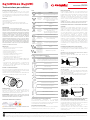
Installazione su valvole termost. Giacomini con attacco
M30 x 1,5 mm (serie H e HDB)
Avvitare la ghiera (B) della testa sulla valvola del
radiatore (A).
AB
CC+D
D
P
B
Installazione su altre valvole termost. Giacomini (eccetto
valvole serie DB)
Per l’installazione su altri corpi valvola termostatizzabili
Giacomini utilizzare la ghiera R453HY012 compresa
nella confezione dela testa.
Applicare la ghiera letta (C) agganciandola ai pioli di
riferimento (P) presenti sulla valvola (D) del radiatore.
AB
CC+D
D
P
B
Avvitare la ghiera (B) della testa sulla valvola del
radiatore (C+D).
AB
C
C+D
D
P
B
Rimozione della testa e disassociazione dall’unità
di controllo (ripristino impostazioni di fabbrica)
Per disassociare una testa K47oW associata all’unità
di controllo KD410 è necessario aprire il vano batteria
della testa e premere il pulsante di reset.
Il led mostrerà dapprima la scritta “LE”, poi un
conteggio no a “10” ed inne la scritta “PA”.
Quando comparirà la scritta “PA” la testa risulterà
disassociata e potrà essere rimossa dalla valvola
svitando la ghiera.
Tutela dell’ambiente.
A decorrere dalla data di attuazione delle direttive europee 2002/96/CE e 2006/66/CEG, nel diritto nazionale si applica quanto segue: i dispositivi elettrici e elettronici e le batterie non
devono mai essere smaltiti con i riuti domestici. Il consumatore è tenuto per legge a smaltire alla ne della loro vita utile le apparecchiature e le batterie elettriche ed elettroniche negli appositi centri di raccolta
o restituirle al negozio di vendita. I dettagli in questo campo sono disciplinati dai rispettivi diritti nazionali. Il simbolo sul prodotto, sulle istruzioni per l’uso o sulla confezione si riferisce a queste disposizioni. Con
il riutilizzo, il riciclaggio dei materiali o altre forme di riciclaggio di vecchi dispositivi / batterie, si dà un importante contributo alla protezione dell'ambiente.

Instruction
047U59428 04/2023
K470WX021 (K470W)
Wireless head for radiator
User manual and Guarantee
Please read this User Manual carefully before installing
the K470WX021 head and store this manual for
documentation.
Supply
1 wireless head K470WX021
1 instruction
1 adaptor ring nut for Giacomini Clip-Clap valves (except
DB series valves).
WARNINGS.
K470WX021 head is designed for use in buildings.
Operate K470WX021 head only as described in the user manual.
K470WX021 head should only be put to use in a dry and dust-free place,
away from direct sunlight.
Do not keep using the device when there is obvious damage.
K470WX021 head may not be rebuilt, modied or opened.
Never recharge batteries, do not short circuit them, do not take them
apart - Risk of explosion! Remove dead batteries from the device
immediately.
Do not use old and new batteries together. Clean battery and device
contacts before inserting if necessary.
Keep batteries away from children. Avoid contact with skin, eyes and
mucous membranes. In case of contact with battery acid, rinse the
affected areas immediately with plenty of water, and seek medical
attention immediately.
Technical data
• Communication Standard: HA 1.2 ZigBee
• Radio frequency: 2,4 GHz
• Power supply: 2 batteries 1,5 V, AA type
• Protection degree: IP20
• Degree of contamination: 2
• Temperature control range: 8÷28 °C
• Working temperature: 0÷50 °C
• Storage temperature: -20÷70 °C
• Type of casing: white ABS
• Valve connection: M30x1,5 mm, with R453HY012
adaptor for other Giacomini valve bodies (except DB
series valves)
• Operation only in combination with KD410 Connect-
TRV control unit, for the remote management of
heating system (KLIMAdomotic TRV series)
Insert / replace batteries
Remove the head cover by pulling it o.
Insert the batteries in the correct orientation, then close
the cover. The K470W head conguration will not change
when replacing the batteries.
RESET
Operation
The K470W wireless head works only in combination
with the KD410 Connect-TRV control unit for remote
management of the heating system (KLIMAdomotic
TRV series).
WARNING. Keeping the KD410 Connect-TRV off for long periods can
cause an higher consumption of the batteries of the K470WX021 head
for radiators.
Possible installation positions
Installation positions not recommended as the radiator temperature
may affect the head.
Buttons
BUTTON STATUS FUNCTION
Press once shortly Reduces the desired temperature by 0,5 °C
Press and hold
Reduces instantaneously the desired
temperature by 0,5 °C and keeps reducing it
by 0,5 °C every 0,5 seconds till the button is
pressed or up to the end value
Double click Activation of “Energy-saving” mode
Press once shortly Increases the desired temperature by 0,5 °C
Press and hold
Increases instantaneously the desired
temperature by 0,5 °C and keeps increasing
it by 0,5 °C every 0,5 seconds till the button
is pressed or up to the end value
Double click Activation of “Comfort” mode
RESET BUT-
TON INSIDE
BAT TERY
COMPA RT-
MENT
Hold and press
for 5 s
Unpairing of head from KD410 control unit
(LEAVE)
RESET BUT-
TON INSIDE
BAT TERY
COMPA RT-
MENT
Hold and press
for 10 s Reset of factory settings
Hold and press
for 3 s
Activates or deactivates the “Child safety”
function
When “Ad” is
displayed: hold and
press for 3 s
Adaption to valve body
LED display and error signals
LED MEANING
Status of wireless connection and pairing.
Turns on when the wireless connection is established.
Turns off when the wireless connection is lost.
Valve pairing
Valve removal (LEAVE)
Adaption to valve body
Lights up during adaption procedure
Lights up when the buttons are locked for
activation/deactivation of the “Child Safety” function
Lights up when the battery charge is lower than 15%
Valve removal failed
No valve movement possible
No valve read
Closing point not read
Valve pairing failed
Setting the desired temperature
The desired temperature can be set only through the
KD410 Connect-TRV control unit to control the heating
system (KLIMAdomotic TRV series) from remote.
Child Safety Function
Press the and buttons for 3 seconds to activate/
deactivate the Child Safety function.
Start up
K470W heads are not paired to any KD410 control unit
upon production. For proper use, the head must be
paired to a KD410 control unit.
The head can be removed from the KD410 Connect-
TRV control unit whenever needed.
Pairing and removal must be performed from the
KD410 Connect-TRV control unit.
NOTE. To pair or remove the K470W head to or from the KD410
control unit, also make reference to the KD410Y002 Connect-TRV user
manual.
Installing the head and pairing to the control unit
From the KD410 control unit, add a new valve in the
desired room. Insert the batteries in the K470W head
(see “Installing the batteries”), “PA” will appear on
the display and a 99-sec countdown will start while
pairing of the head and the control unit is in progress.
Once the pairing is completed, the wireless symbol
will blink and the “Ad” led will be displayed.
Now the head can be installed on the radiator valve
(see “Installing the head on the valve body”); press the
and buttons to adapt the head to the valve stroke;
6 led symbols will start blinking.
Once the head is adapted, the display will show the
desired temperature.
Installing the head on the valve body
The head can be installed on the valve body once the
K470W head and the KD410 control unit are paired.
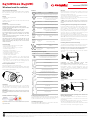
Installation on Giacomini valves with thermostatic option
with M30 x 1.5 mm connection (H and HDB series)
Screw the ring nut (B) of the head onto the radiator
valve (A).
AB
CC+D
D
P
B
Installation on other Giacomini valves with
thermostatic option (except DB series valves)
For installation on other Giacomini valve bodies with
thermostatic option, use the R453HY012 ring nut
included in the head package. Install the threaded
ring nut (C) hooking it to the reference pins (P) on the
radiator valve (D).
AB
CC+D
D
P
B
Screw the ring nut (B) of the head on the radiator valve
(C + D).
AB
C
C+D
D
P
B
Removing the head and unpairing from control unit
(factory setting reset)
To unpair a K470W head from the KD410 control unit,
open the head battery compartment and press the
reset button.
First “LE” will be displayed, then a “10-sec” countdown
will start and nally the “PA” led will appear.
This means that the head has been unpaired and that
it can be removed by unscrewing the ring nut.
Environmental Protection. From the date of implementation of European guidelines 2012/19/EU into national law, the following applies: Electric and electronic devices and batteries may not be disposed of in
household waste. The consumer is obliged to return electric and electronic devices and batteries to the public collection points established for them or to the point of sale. The particulars of this are regulated
by the applicable state laws. The symbol on the product, operation instructions or packaging points to these provisions. You make an important contribution to the protection of the environment by reusing or
recycling old equipment/batteries or making use of them in other ways.
-
 1
1
-
 2
2


in altre lingue
Documenti correlati
-
Giacomini KD410 Manuale utente
-
-
-
-
-
-
-
-
-