
Quick Start Guide
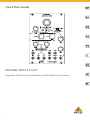
MODAMP MODULE 1005
Legendary 2500 Series Ring Modulator and VCA Module for Eurorack
V 1.0

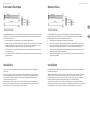
LEGAL DISCLAIMER
Music Tribe accepts no liability for any loss
which may be suered by any person who
relies either wholly or in part upon any
description, photograph, or statement
contained herein. Technical specications,
appearances and other information are
subject to change without notice. All
trademarks are the property of their
respective owners. Midas, Klark Teknik,
Lab Gruppen, Lake, Tannoy, Turbosound,
TC Electronic, TC Helicon, Behringer, Bugera,
Oberheim, Auratone, Aston Microphones,
Aston Microphones and Coolaudio are
trademarks or registered trademarks of
Music Tribe Global Brands Ltd. © Music Tribe
Global Brands Ltd. 2021 All rights reserved.
LIMITED WARRANTY
For the applicable warranty terms and
conditions and additional information
regarding Music Tribe’s Limited Warranty,
please see complete details online at
musictribe.com/warranty.
NEGACIÓN LEGAL
Music Tribe no admite ningún tipo de
responsabilidad por cualquier daño o
pérdida que pudiera sufrir cualquier persona
por conar total o parcialmente en la
descripciones, fotografías o armaciones
contenidas en este documento. Las
especicaciones técnicas, imágenes y
otras informaciones contenidas en este
documento están sujetas a modicaciones
sin previo aviso. Todas las marcas comerciales
que aparecen aquí son propiedad de sus
respectivos dueños. Midas, Klark Teknik,
Lab Gruppen, Lake, Tannoy, Turbosound,
TC Electronic, TC Helicon, Behringer, Bugera,
Oberheim, Auratone, Aston Microphones
y Coolaudio son marcas comerciales o
marcas registradas de Music Tribe Global
Brands Ltd. © Music Tribe Global Brands Ltd.
2021 Reservados todos los derechos.
GARANTÍA LIMITADA
Si quiere conocer los detalles y condiciones
aplicables de la garantía así como
información adicional sobre la Garantía
limitada de Music Tribe, consulte online
toda la información en la web
musictribe.com/warranty.
DÉNI LÉGAL
Music Tribe ne peut être tenu pour
responsable pour toute perte pouvant
être subie par toute personne se ant en
partie ou en totalité à toute description,
photographie ou armation contenue
dans ce document. Les caractéristiques,
l’apparence et d’autres informations
peuvent faire l’objet de modications
sans notication. Toutes les marques
appartiennent à leurs propriétaires
respectifs. Midas, Klark Teknik, Lab Gruppen,
Lake, Tannoy, Turbosound, TC Electronic,
TC Helicon, Behringer, Bugera, Oberheim,
Auratone, Aston Microphones et Coolaudio
sont des marques ou marques déposées de
Music Tribe Global Brands Ltd. © Music Tribe
Global Brands Ltd. 2021 Tous droits réservés.
GARANTIE LIMITÉE
Pour connaître les termes et conditions
de garantie applicables, ainsi que les
informations supplémentaires et
détaillées sur la Garantie Limitée de
Music Tribe, consultez le site Internet
musictribe.com/warranty.
HAFTUNGSAUSSCHLUSS
Music Tribe übernimmt keine Haftung für
Verluste, die Personen entstanden sind, die
sich ganz oder teilweise auf hier enthaltene
Beschreibungen, Fotos oder Aussagen
verlassen haben. Technische Daten,
Erscheinungsbild und andere Informationen
können ohne vorherige Ankündigung
geändert werden. Alle Warenzeichen sind
Eigentum der jeweiligen Inhaber. Midas,
Klark Teknik, Lab Gruppen, Lake, Tannoy,
Turbosound, TC Electronic, TC Helicon,
Behringer, Bugera, Oberheim, Auratone,
Aston Microphones und Coolaudio
sind Warenzeichen oder eingetragene
Warenzeichen der Music Tribe Global Brands
Ltd. © Music Tribe Global Brands Ltd. 2021
Alle Rechte vorbehalten.
BESCHRÄNKTE GARANTIE
Die geltenden Garantiebedingungen und
zusätzliche Informationen bezüglich der
von Music Tribe gewährten beschränkten
Garantie nden Sie online unter
musictribe.com/warranty.
LEGAL RENUNCIANTE
O Music Tribe não se responsabiliza por
perda alguma que possa ser sofrida por
qualquer pessoa que dependa, seja de
maneira completa ou parcial, de qualquer
descrição, fotograa, ou declaração aqui
contidas. Dados técnicos, aparências
e outras informações estão sujeitas a
modicações sem aviso prévio. Todas
as marcas são propriedade de seus
respectivos donos. Midas, Klark Teknik,
Lab Gruppen, Lake, Tannoy, Turbosound,
TC Electronic, TC Helicon, Behringer, Bugera,
Oberheim, Auratone, Aston Microphones
e Coolaudio são marcas ou marcas
registradas do Music Tribe Global Brands
Ltd. © Music Tribe Global Brands Ltd.
2021 Todos direitos reservados.
GARANTIA LIMITADA
Para obter os termos de garantia aplicáveis
e condições e informações adicionais a
respeito da garantia limitada do Music Tribe,
favor vericar detalhes na íntegra através do
website musictribe.com/warranty.
DISCLAIMER LEGALE
Music Tribe non si assume alcuna
responsabilità per eventuali danni che
possono essere subiti da chiunque si adi
in tutto o in parte a qualsiasi descrizione,
fotograa o dichiarazione contenuta
qui. Speciche tecniche, aspetti e altre
informazioni sono soggette a modiche
senza preavviso. Tutti i marchi sono di
proprietà dei rispettivi titolari. Midas,
Klark Teknik, Lab Gruppen, Lake, Tannoy,
Turbosound, TC Electronic, TC Helicon,
Behringer, Bugera, Oberheim, Auratone,
Aston Microphones e Coolaudio sono marchi
o marchi registrati di Music Tribe Global
Brands Ltd. © Music Tribe Global Brands
Ltd. 2021 Tutti i diritti riservati.
GARANZIA LIMITATA
Per i termini e le condizioni di garanzia
applicabili e le informazioni aggiuntive
relative alla garanzia limitata di Music Tribe,
consultare online i dettagli completi su
musictribe.com/warranty.
WETTELIJKE ONTKENNING
Music Tribe aanvaardt geen
aansprakelijkheid voor enig verlies dat
kan worden geleden door een persoon die
geheel of gedeeltelijk vertrouwt op enige
beschrijving, foto of verklaring hierin.
Technische specicaties, verschijningen
en andere informatie kunnen zonder
voorafgaande kennisgeving worden
gewijzigd. Alle handelsmerken zijn
eigendom van hun respectievelijke
eigenaren. Midas, Klark Teknik, Lab
Gruppen, Lake, Tannoy, Turbosound,
TC Electronic, TC Helicon, Behringer, Bugera,
Oberheim, Auratone, Aston Microphones
en Coolaudio zijn handelsmerken of
gedeponeerde handelsmerken van Music
Tribe Global Brands Ltd. © Music Tribe
Global Brands Ltd. 2021 Alle rechten
voorbehouden.
BEPERKTE GARANTIE
Voor de toepasselijke garantievoorwaarden
en aanvullende informatie met betrekking
tot de beperkte garantie van Music Tribe,
zie de volledige details online op
musictribe.com/warranty.
FRISKRIVNINGSKLAUSUL
Music Tribe tar inget ansvar för någon
förlust som kan drabbas av någon person
som helt eller delvis förlitar sig på någon
beskrivning, fotogra eller uttalande
som nns här. Tekniska specikationer,
utseenden och annan information kan
ändras utan föregående meddelande. Alla
varumärken tillhör respektive ägare. Midas,
Klark Teknik, Lab Gruppen, Lake, Tannoy,
Turbosound, TC Electronic, TC Helicon,
Behringer, Bugera, Oberheim, Auratone,
Aston Microphones och Coolaudio är
varumärken eller registrerade varumärken
som tillhör Music Tribe Global Brands Ltd.
© Music Tribe Global Brands Ltd. 2021 Alla
Rättigheter reserverade.
BEGRÄNSAD GARANTI
För tillämpliga garantivillkor och ytterligare
information om Music Tribes begränsade
garanti, se fullständig information online på
musictribe.com/warranty.
ZASTRZEŻENIA PRAWNE
Music Tribe nie ponosi odpowiedzialności
za jakiekolwiek straty, które mogą ponieść
osoby, które polegają w całości lub w
części na jakimkolwiek opisie, fotograi
lub oświadczeniu zawartym w niniejszym
dokumencie. Specykacje techniczne,
wygląd i inne informacje mogą ulec zmianie
bez powiadomienia. Wszystkie znaki
towarowe są własnością ich odpowiednich
właścicieli. Midas, Klark Teknik,
Lab Gruppen, Lake, Tannoy, Turbosound,
TC Electronic, TC Helicon, Behringer, Bugera,
Oberheim, Auratone, Aston Microphones
i Coolaudio są znakami towarowymi lub
zastrzeżonymi znakami towarowymi rmy
Music Tribe Global Brands Ltd. © Music Tribe
Global Brands Ltd. 2021 Wszystkie prawa
zastrzeżone.
OGRANICZONA
GWARANCJA
Aby zapoznać się z obowiązującymi
warunkami gwarancji i dodatkowymi
informacjami dotyczącymi ograniczonej
gwarancji Music Tribe, zapoznaj się ze
wszystkimi szczegółami w trybie online pod
adresem musictribe.com/warranty.
2 3Quick Start GuideMODAMP MODULE 1005

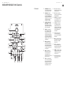
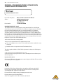
MODAMP MODULE 1005 Controls
(1)
(2)
(3)
(4)
(5)
(6)
(7)
(8)
(9)
(10)
(11)
(12)
(13)
(14) (15) (16)
4 5Quick Start GuideMODAMP MODULE 1005
(1) AMPLIFIER GAIN – This knob
controls the VCA’s gain and nal
output volume at the OUT jack.
(2) UNMOD GAIN – This knob
controls the IN A signal gain when
the module is in UNMOD mode (as
indicated by the UNMOD button).
UNMOD mode allows the module
to be used as a VCA when
modulation is not required.
(3) AMPLIFIER CONTROL MODE
(EXP’L/LINEAR) – This sliding
switch determines whether the
VCA gain response is exponential
(EXP’L) or linear (LINEAR).
(4) UNMOD – Press this button to
place the module into UNMOD
mode. In UNMOD mode, the IN
A signal passes to the OUT jack
without any modulation, and the
signal level is controlled by both
the UNMOD GAIN and AMPLIFIER
GAIN knobs. IN B does not function
in UNMOD mode.
(5) MOD – Press the button to
activate MOD mode. In MOD
mode, the circuit combines the
IN A signal and the IN B signal to
produce an output signal that is
a modulated combination of the
two input signals.
(6) RATIO – Use this knob in
MOD mode to oset the tune
control voltage that is sent
out through the CV B jack.
This function only operates when
MOD mode is selected.
(7) TUNE – Use this knob in MOD
mode to control the output level of
the tune control voltage sent out
through both the CV A and CV B
jacks. This function only operates
when MOD mode is selected.
(8) IN A – This knob controls the
input level for the signal coming in
through the IN A jack.
(9) IN B – This knob controls the
input level for the signal coming in
through the IN B jack.
(10) IN A / IN B – Use these input jacks
to route in audio signals for the
internal modulation process via
cables with 3.5 mm connectors.
(11) CV A / CV B – Use these jacks
to route TUNE (CV A and CV B)
and RATIO (CV B oset) control
voltages out to the two VCOs that
typically supply the audio signals
to the IN A and IN B inputs to
be modulated.
(12) CV IN – Use this jack to route
in control voltage signals for
remote control of the AMPLIFIER
GAIN setting.
(13) MOD – Use this jack to route in a
trigger signal to remotely activate
MOD mode via a cable with 3.5
mm connectors.
(14) GATE – Use this input jack to
route in a gate signal to turn the
modulation circuit on and o via a
cable with 3.5 mm connectors.
(15) UNMOD – Use this jack to route in
a trigger signal to remotely switch
o MOD mode via a cable with
3.5 mm connectors.
(16) OUT – This jack sends out the
nal VCA signal via cable with
3.5 mm connectors.
(EN) Controls

6 7Quick Start GuideMODAMP MODULE 1005
(FR) Réglages(ES) Controles
MODAMP MODULE 1005 Controls
(1) GAIN AMPLIFICATEUR – Ce
bouton contrôle le gain du VCA
et le volume de sortie nal à la
prise OUT.
(2) UNMOD GAIN – Ce bouton
contrôle le gain du signal IN A
lorsque le module est en mode
UNMOD (comme indiqué par le
bouton UNMOD). Le mode UNMOD
permet au module d’être utilisé
comme VCA lorsque la modulation
n’est pas requise.
(3) MODE DE CONTRÔLE DE
L’AMPLIFICATEUR (EXP’L/
LINÉAIRE) – Ce commutateur à
glissière détermine si la réponse
de gain du VCA est exponentielle
(EXP’L) ou linéaire (LINEAR).
(4) UNMOD – Appuyez sur ce bouton
pour mettre le module en mode
UNMOD. En mode UNMOD, le
signal IN A passe à la prise OUT
sans aucune modulation et le
niveau du signal est contrôlé
par les boutons UNMOD GAIN
et AMPLIFIER GAIN. IN B ne
fonctionne pas en mode UNMOD.
(5) MOD – Appuyez sur le bouton
pour activer le mode MOD. En
mode MOD, le circuit combine le
signal IN A et le signal IN B pour
produire un signal de sortie qui
est une combinaison modulée des
deux signaux d’entrée.
(6) RAPPORT – Utilisez ce bouton
en mode MOD pour compenser la
tension de commande de réglage
envoyée via la prise CV B. Cette
fonction ne fonctionne que lorsque
le mode MOD est sélectionné.
(7) RÉGLER – Utilisez ce bouton
en mode MOD pour contrôler le
niveau de sortie de la tension de
commande de réglage envoyée
via les prises CV A et CV B. Cette
fonction ne fonctionne que lorsque
le mode MOD est sélectionné.
(8) DANS UN – Ce bouton contrôle le
niveau d’entrée du signal entrant
via la prise IN A.
(9) EN B – Ce bouton contrôle le
niveau d’entrée du signal entrant
via la prise IN B.
(10) EN A / EN B – Utilisez ces prises
d’entrée pour acheminer les
signaux audio pour le processus de
modulation interne via des câbles
avec des connecteurs de 3,5 mm.
(11) CV A / CV B – Utilisez ces prises
pour acheminer les tensions de
commande TUNE (CV A et CV B)
et RATIO (décalage CV B) vers
les deux VCO qui fournissent
généralement les signaux audio
aux entrées IN A et IN B à moduler.
(12) CV IN – Utilisez cette prise
pour acheminer les signaux
de tension de commande pour
la télécommande du réglage
AMPLIFIER GAIN.
(13) MOD – Utilisez cette prise
pour acheminer un signal de
déclenchement pour activer à
distance le mode MOD via un câble
avec des connecteurs de 3,5 mm.
(14) PORTAIL – Utilisez cette prise
d’entrée pour acheminer un signal
de porte pour activer et désactiver
le circuit de modulation via un câble
avec des connecteurs de 3,5 mm.
(15) UNMOD – Utilisez cette prise
pour acheminer un signal de
déclenchement pour désactiver à
distance le mode MOD via un câble
avec des connecteurs de 3,5 mm.
(16) EN DEHORS – Cette prise envoie
le signal VCA nal via un câble
avec des connecteurs de 3,5 mm.
(1) GANANCIA DEL AMPLIFICADOR
– Esta perilla controla la ganancia
del VCA y el volumen de salida
nal en el jack OUT.
(2) UNMOD GANANCIA – Esta perilla
controla la ganancia de la señal IN
A cuando el módulo está en modo
UNMOD (como lo indica el botón
UNMOD). El modo UNMOD permite
utilizar el módulo como VCA cuando
no se requiere modulación.
(3) MODO DE CONTROL DEL
AMPLIFICADOR (EXP’L/LINEAR)
– Este interruptor deslizante
determina si la respuesta de
ganancia de VCA es exponencial
(EXP’L) o lineal (LINEAR).
(4) UNMOD – Presione este botón para
colocar el módulo en modo UNMOD.
En el modo UNMOD, la señal IN
A pasa al jack OUT sin ninguna
modulación, y el nivel de la señal es
controlado por los mandos UNMOD
GAIN y AMPLIFIER GAIN. IN B no
funciona en modo UNMOD.
(5) MODIFICACIÓN – Presione el
botón para activar el modo MOD.
En el modo MOD, el circuito
combina la señal IN A y la señal IN
B para producir una señal de salida
que es una combinación modulada
de las dos señales de entrada.
(6) PROPORCIÓN – Utilice esta
perilla en el modo MOD para
compensar el voltaje de control
de sintonía que se envía a través
del conector CV B. Esta función
solo opera cuando se selecciona el
modo MOD.
(7) MELODÍA – Use esta perilla en el
modo MOD para controlar el nivel
de salida del voltaje de control de
sintonía enviado a través de las
tomas CV A y CV B. Esta función
solo opera cuando se selecciona el
modo MOD.
(8) EN UN – Esta perilla controla el
nivel de entrada de la señal que
ingresa a través de la toma IN A.
(9) EN B – Esta perilla controla el
nivel de entrada de la señal que
ingresa a través de la toma IN B.
(10) EN A / EN B – Utilice estas tomas
de entrada para enrutar señales
de audio para el proceso de
modulación interna a través de
cables con conectores de 3,5 mm.
(11) CV A / CV B – Utilice estas tomas
para enrutar los voltajes de control
de TUNE (CV A y CV B) y RATIO
(compensación de CV B) hacia
los dos VCO que normalmente
suministran las señales de audio
a las entradas IN A e IN B para
ser moduladas.
(12) CV IN – Utilice este conector para
enrutar señales de voltaje de
control para el control remoto del
ajuste AMPLIFIER GAIN.
(13) MODIFICACIÓN – Utilice este
conector para enrutar una señal
de disparo para activar de forma
remota el modo MOD a través de un
cable con conectores de 3,5 mm.
(14) PORTÓN – Utilice este conector de
entrada para enrutar una señal de
puerta para encender y apagar el
circuito de modulación a través de
un cable con conectores de 3,5 mm.
(15) UNMOD – Utilice este conector
para enrutar una señal de disparo
para apagar de forma remota el
modo MOD a través de un cable
con conectores de 3,5 mm.
(16) FUERA – Este conector envía la
señal VCA nal a través de un cable
con conectores de 3,5 mm.

8 9Quick Start GuideMODAMP MODULE 1005
(PT) Controles(DE) Bedienelemente
MODAMP MODULE 1005 Controls
(1) GANHO DE AMPLIFICADOR –
Este botão controla o ganho do
VCA e o volume de saída nal no
conector OUT.
(2) GANHO UNMOD – Este botão
controla o ganho do sinal IN A
quando o módulo está no modo
UNMOD (conforme indicado pelo
botão UNMOD). O modo UNMOD
permite que o módulo seja
usado como um VCA quando a
modulação não for necessária.
(3) MODO DE CONTROLE DO
AMPLIFICADOR (EXP’L/LINEAR)
– Esta chave deslizante
determina se a resposta de
ganho VCA é exponencial (EXP’L)
ou linear (LINEAR).
(4) UNMOD – Pressione este botão
para colocar o módulo no modo
UNMOD. No modo UNMOD, o sinal
IN A passa para o conector OUT
sem qualquer modulação, e o nível
do sinal é controlado pelos botões
UNMOD GAIN e AMPLIFIER GAIN. IN
B não funciona no modo UNMOD.
(5) MOD – Pressione o botão para
ativar o modo MOD. No modo
MOD, o circuito combina o sinal
IN A e o sinal IN B para produzir
um sinal de saída que é uma
combinação modulada dos dois
sinais de entrada.
(6) RAZÃO – Use este botão no modo
MOD para compensar a tensão de
controle da anação que é enviada
através do conector CV B. Esta
função só opera quando o modo
MOD é selecionado.
(7) AFINAÇÃO – Use este botão no
modo MOD para controlar o nível
de saída da tensão de controle da
anação enviada pelos conectores
CV A e CV B. Esta função só opera
quando o modo MOD é selecionado.
(8) EM UM – Este botão controla o
nível de entrada do sinal que entra
pelo conector IN A.
(9) EM B – Este botão controla o nível
de entrada do sinal que entra pelo
conector IN B.
(10) IN A / IN B – Use esses conectores
de entrada para rotear sinais
de áudio para o processo de
modulação interna por meio de
cabos com conectores de 3,5 mm.
(11) CV A / CV B – Use esses conectores
para rotear as tensões de controle
TUNE (CV A e CV B) e RATIO (CV
B oset) para os dois VCOs que
normalmente fornecem os sinais
de áudio para as entradas IN A e IN
B a serem moduladas.
(12) CV IN – Use este conector
para rotear sinais de tensão de
controle para controle remoto da
conguração AMPLIFIER GAIN.
(13) MOD – Use este conector para
rotear um sinal de disparo para
ativar remotamente o modo
MOD por meio de um cabo com
conectores de 3,5 mm.
(14) PORTÃO – Use este conector
de entrada para rotear um sinal
de portão para ligar e desligar
o circuito de modulação por meio
de um cabo com conectores
de 3,5 mm.
(15) UNMOD – Use este conector para
rotear um sinal de disparo para
desligar remotamente o modo
MOD por meio de um cabo com
conectores de 3,5 mm.
(16) FORA – Este conector envia o sinal
VCA nal por meio de um cabo
com conectores de 3,5 mm.
(1) VERSTÄRKER GEWINNEN
– Dieser Regler steuert die
Verstärkung und die endgültige
Ausgangslautstärke des VCA an
der OUT-Buchse.
(2) UNMOD GAIN – Dieser Regler
steuert die Signalverstärkung IN A,
wenn sich das Modul im UNMOD-
Modus bendet (wie durch die
UNMOD-Taste angezeigt). Im
UNMOD-Modus kann das Modul
als VCA verwendet werden, wenn
keine Modulation erforderlich ist.
(3) VERSTÄRKER-
STEUERUNGSMODUS (EXP’L/
LINEAR) – Dieser Schiebeschalter
bestimmt, ob die VCA-
Verstärkungsantwort exponentiell
(EXP’L) oder linear (LINEAR) ist.
(4) UNMOD – Drücken Sie diese
Taste, um das Modul in den
UNMOD-Modus zu versetzen.
Im UNMOD-Modus wird das IN
A-Signal ohne Modulation an die
OUT-Buchse weitergeleitet, und
der Signalpegel wird sowohl über
den UNMOD GAIN- als auch den
AMPLIFIER GAIN-Regler gesteuert.
IN B funktioniert im UNMOD-
Modus nicht.
(5) MOD – Drücken Sie die Taste, um
den MOD-Modus zu aktivieren.
Im MOD-Modus kombiniert
die Schaltung das IN A-Signal
und das IN B-Signal, um ein
Ausgangssignal zu erzeugen, das
eine modulierte Kombination der
beiden Eingangssignale ist.
(6) VERHÄLTNIS – Verwenden Sie
diesen Knopf im MOD-Modus,
um die über die CV B-Buchse
gesendete Tuning-Steuerspannung
zu versetzen. Diese Funktion
funktioniert nur, wenn der MOD-
Modus ausgewählt ist.
(7) MELODIE – Verwenden Sie
diesen Regler im MOD-Modus, um
den Ausgangspegel der Tuning-
Steuerspannung zu steuern, die
über die Buchsen CV A und CV B
gesendet wird. Diese Funktion
funktioniert nur, wenn der MOD-
Modus ausgewählt ist.
(8) IN EINEM – Dieser Regler steuert
den Eingangspegel für das über die
IN A-Buchse eingehende Signal.
(9) IN B. – Dieser Regler steuert den
Eingangspegel für das über die IN
B-Buchse eingehende Signal.
(10) IN A / IN B. – Verwenden Sie
diese Eingangsbuchsen, um
Audiosignale für den internen
Modulationsprozess über Kabel
mit 3,5-mm-Steckern einzuleiten.
(11) CV A / CV B. – Verwenden
Sie diese Buchsen, um die
Steuerspannungen TUNE (CV A
und CV B) und RATIO (CV B Oset)
an die beiden VCOs zu leiten, die
normalerweise die Audiosignale
an die zu modulierenden Eingänge
IN A und IN B liefern.
(12) CV IN – Verwenden
Sie diese Buchse, um
Steuerspannungssignale für die
Fernsteuerung der Einstellung
AMPLIFIER GAIN einzuleiten.
(13) MOD – Verwenden Sie diese
Buchse, um ein Triggersignal
zu leiten und den MOD-
Modus über ein Kabel mit
3,5-mm-Anschlüssen aus der
Ferne zu aktivieren.
(14) TOR – Verwenden Sie diese
Eingangsbuchse, um ein Gate-
Signal einzuleiten und den
Modulationskreis über ein Kabel
mit 3,5-mm-Steckern ein-
und auszuschalten.
(15) UNMOD – Verwenden Sie diese
Buchse, um ein Triggersignal
zu leiten und den MOD-
Modus über ein Kabel mit
3,5-mm-Anschlüssen aus der
Ferne auszuschalten.
(16) AUS – Diese Buchse sendet das
endgültige VCA-Signal über ein
Kabel mit 3,5-mm-Steckern.

10 11Quick Start GuideMODAMP MODULE 1005
(NL) Bediening(IT) Controlli
MODAMP MODULE 1005 Controls
(1) VERSTERKER WINST – Deze knop
regelt de versterking van de VCA en
het uiteindelijke uitgangsvolume
op de OUT-aansluiting.
(2) UNMOD WINST – Deze knop
regelt de IN A-signaalversterking
wanneer de module in UNMOD-
modus is (zoals aangegeven door
de UNMOD-knop). Met de UNMOD-
modus kan de module worden
gebruikt als een VCA wanneer
modulatie niet vereist is.
(3) REGELMODUS VERSTERKER
(EXP’L/LINEAR) – Deze
schuifschakelaar bepaalt of
de VCA-versterkingsrespons
exponentieel (EXP’L) of lineair
(LINEAIR) is.
(4) UNMOD – Druk op deze knop om
de module in de UNMOD-modus
te plaatsen. In de UNMOD-
modus gaat het IN A-signaal
zonder enige modulatie naar de
OUT-aansluiting en wordt het
signaalniveau bestuurd door
zowel de UNMOD GAIN- als de
AMPLIFIER GAIN-knoppen. IN B
werkt niet in UNMOD-modus.
(5) MOD – Druk op de knop om de
MOD-modus te activeren. In de
MOD-modus combineert het
circuit het IN A-signaal en het IN
B-signaal om een uitgangssignaal
te produceren dat een
gemoduleerde combinatie is van
de twee ingangssignalen.
(6) VERHOUDING – Gebruik deze
knop in de MOD-modus om de
afstemregelspanning die via de CV
B-aansluiting wordt uitgezonden,
te compenseren. Deze functie
werkt alleen als de MOD-modus
is geselecteerd.
(7) AFSTEMMEN – Gebruik deze
knop in de MOD-modus om het
uitgangsniveau te regelen van
de stemregelspanning die wordt
uitgezonden via zowel de CV
A- als de CV B-aansluitingen. Deze
functie werkt alleen als de MOD-
modus is geselecteerd.
(8) IN EEN – Deze knop regelt het
ingangsniveau voor het signaal
dat binnenkomt via de IN
A-aansluiting.
(9) IN B – Deze knop regelt het
ingangsniveau voor het signaal
dat binnenkomt via de IN
B-aansluiting.
(10) IN A / IN B – Gebruik deze
ingangsjacks om audiosignalen
voor het interne modulatieproces
binnen te leiden via kabels met
3,5 mm-connectoren.
(11) CV A / CV B – Gebruik deze
aansluitingen om TUNE (CV
A en CV B) en RATIO (CV B
oset) stuurspanningen naar
de twee VCO’s te sturen die de
audiosignalen doorgaans naar de
IN A en IN B ingangen sturen om te
worden gemoduleerd.
(12) CV IN – Gebruik deze aansluiting
om stuurspanningssignalen door
te sturen voor afstandsbediening
van de AMPLIFIER GAIN-instelling.
(13) MOD – Gebruik deze aansluiting
om een triggersignaal in te leiden
om de MOD-modus op afstand te
activeren via een kabel met
3,5 mm-connectoren.
(14) POORT – Gebruik deze ingang
om een poortsignaal in te leiden
om het modulatiecircuit aan en
uit te zetten via een kabel met
3,5 mm connectoren.
(15) UNMOD – Gebruik deze
aansluiting om een triggersignaal
in te leiden om de MOD-modus op
afstand uit te schakelen via een
kabel met 3,5 mm-connectoren.
(16) UIT – Deze aansluiting stuurt het
uiteindelijke VCA-signaal via een
kabel met 3,5 mm-connectoren.
(1) GUADAGNO
DELL’AMPLIFICATORE – Questa
manopola controlla il guadagno
del VCA e il volume di uscita nale
al jack OUT.
(2) UNMOD GAIN – Questa manopola
controlla il guadagno del segnale
IN A quando il modulo è in
modalità UNMOD (come indicato
dal pulsante UNMOD). La modalità
UNMOD consente di utilizzare il
modulo come VCA quando non è
richiesta la modulazione.
(3) MODALITÀ DI CONTROLLO
AMPLIFICATORE (EXP’L/ LINEAR)
– Questo interruttore a scorrimento
determina se la risposta del
guadagno VCA è esponenziale
(EXP’L) o lineare (LINEAR).
(4) UNMOD – Premere questo
pulsante per mettere il modulo
in modalità UNMOD. In modalità
UNMOD, il segnale IN A passa
alla presa OUT senza alcuna
modulazione e il livello del segnale
è controllato dalle manopole
UNMOD GAIN e AMPLIFIER GAIN. IN
B non funziona in modalità UNMOD.
(5) MOD – Premere il pulsante per
attivare la modalità MOD. In
modalità MOD, il circuito combina
il segnale IN A e il segnale IN B per
produrre un segnale di uscita che
è una combinazione modulata dei
due segnali di ingresso.
(6) RAPPORTO – Usa questa
manopola in modalità MOD per
compensare la tensione di controllo
dell’accordatura che viene inviata
attraverso il jack CV B. Questa
funzione è attiva solo quando è
selezionata la modalità MOD.
(7) SINTONIZZARE – Usa questa
manopola in modalità MOD per
controllare il livello di uscita
della tensione di controllo
dell’accordatura inviata attraverso
entrambi i jack CV A e CV B. Questa
funzione è attiva solo quando è
selezionata la modalità MOD.
(8) IN UN – Questa manopola
controlla il livello di ingresso del
segnale in ingresso attraverso il
jack IN A.
(9) IN B – Questa manopola controlla
il livello di ingresso per il segnale
in ingresso attraverso il jack IN B.
(10) IN A / IN B – Utilizzare questi
jack di ingresso per instradare i
segnali audio per il processo di
modulazione interna tramite cavi
con connettori da 3,5 mm.
(11) CV A / CV B – Utilizzare questi jack
per inviare le tensioni di controllo
TUNE (CV A e CV B) e RATIO (oset
CV B) ai due VCO che tipicamente
forniscono i segnali audio agli
ingressi IN A e IN B da modulare.
(12) CV IN – Utilizzare questo jack per
indirizzare i segnali della tensione
di controllo per il controllo remoto
dell’impostazione AMPLIFIER GAIN.
(13) MOD – Utilizzare questo jack
per instradare un segnale di
trigger per attivare a distanza la
modalità MOD tramite un cavo con
connettori da 3,5 mm.
(14) CANCELLO – Utilizzare questo
jack di ingresso per instradare
un segnale di gate per attivare
e disattivare il circuito di
modulazione tramite un cavo con
connettori da 3,5 mm.
(15) UNMOD – Utilizzare questo
jack per instradare un segnale di
trigger per disattivare a distanza
la modalità MOD tramite un cavo
con connettori da 3,5 mm.
(16) SU – Questo jack invia il segnale
VCA nale tramite cavo con
connettori da 3,5 mm.

12 13Quick Start GuideMODAMP MODULE 1005
(PL) Sterowanica(SE) Kontroller
MODAMP MODULE 1005 Controls
(1) WZMOCNIENIE WZMACNIACZA
– To pokrętło kontroluje
wzmocnienie VCA i końcową
głośność wyjściową na
gnieździe OUT.
(2) NIEZWYKŁY ZYSK – Pokrętło to
kontroluje wzmocnienie sygnału
IN A, gdy moduł jest w trybie
UNMOD (jak wskazuje przycisk
UNMOD). Tryb UNMOD pozwala
na użycie modułu jako VCA, gdy
modulacja nie jest wymagana.
(3) TRYB STEROWANIA
WZMACNIACZEM (EXP’L/
LINEAR – Ten przełącznik
suwakowy określa, czy odpowiedź
wzmocnienia VCA jest wykładnicza
(EXP’L), czy liniowa (LINEAR).
(4) UNMOD – Naciśnij ten przycisk,
aby przełączyć moduł w tryb
UNMOD. W trybie UNMOD sygnał
IN A przechodzi do gniazda OUT
bez żadnej modulacji, a poziom
sygnału jest kontrolowany za
pomocą pokręteł UNMOD GAIN i
AMPLIFIER GAIN. IN B nie działa w
trybie UNMOD.
(5) MOD – Naciśnij przycisk, aby
aktywować tryb MOD. W trybie
MOD obwód łączy sygnał IN A i
sygnał IN B w celu wytworzenia
sygnału wyjściowego będącego
modulowaną kombinacją dwóch
sygnałów wejściowych.
(6) STOSUNEK – Użyj tego pokrętła
w trybie MOD, aby zrównoważyć
napięcie sterujące strojeniem, które
jest wysyłane przez gniazdo CV B.
Ta funkcja działa tylko wtedy, gdy
wybrany jest tryb MOD.
(7) MELODIA – Użyj tego pokrętła
w trybie MOD, aby kontrolować
poziom wyjściowy napięcia
sterującego strojeniem wysyłanego
przez gniazda CV A i CV B. Ta funkcja
działa tylko wtedy, gdy wybrany
jest tryb MOD.
(8) W – To pokrętło kontroluje poziom
wejściowy sygnału przychodzącego
przez gniazdo IN A.
(9) IN B – To pokrętło kontroluje
poziom wejściowy sygnału
przychodzącego przez gniazdo IN B.
(10) W A / IN B – Użyj tych gniazd
wejściowych do kierowania
sygnałów audio dla procesu
modulacji wewnętrznej za pomocą
kabli ze złączami 3,5 mm.
(11) CV A / CV B – Za pomocą tych
gniazd można kierować napięcia
sterujące TUNE (CV A i CV B) i RATIO
(przesunięcie CV B) do dwóch
VCO, które zazwyczaj dostarczają
sygnały audio do wejść IN A i IN B,
które mają być modulowane.
(12) CV IN – Użyj tego gniazda do
kierowania sygnałów napięcia
sterującego dla zdalnego
sterowania ustawieniem
WZMOCNIENIA WZMOCNIENIA.
(13) MOD – Użyj tego gniazda
do kierowania sygnału
wyzwalającego, aby zdalnie
aktywować tryb MOD za pomocą
kabla ze złączami 3,5 mm.
(14) BRAMA – Użyj tego gniazda
wejściowego, aby skierować
sygnał bramki do włączania i
wyłączania obwodu modulacji za
pomocą kabla ze złączami 3,5 mm.
(15) UNMOD – Użyj tego gniazda,
aby skierować sygnał wyzwalający
w celu zdalnego wyłączenia
trybu MOD za pomocą kabla ze
złączami 3,5 mm.
(16) NA ZEWNĄTRZ – To gniazdo
wysyła końcowy sygnał VCA za
pomocą kabla ze złączami 3,5 mm.
(1) FÖRSTÄRKARE – Denna ratt
kontrollerar VCA: s förstärkning
och slutliga utgångsvolym vid
OUT-uttaget.
(2) UNMOD VINN – Denna
ratt kontrollerar IN
A-signalförstärkningen när
modulen är i UNMOD-läge (som
indikeras av UNMOD-knappen).
UNMOD-läge gör att modulen
kan användas som en VCA när
modulering inte krävs.
(3) FÖRSTÄRKARE KONTROLLÄGE
(EXP’L/LINEAR) – Denna
skjutbrytare avgör om
VCA-förstärkningssvaret är
exponentiellt (EXP’L) eller
linjärt (LINEAR).
(4) UNMOD – Tryck på den här
knappen för att placera modulen
i UNMOD-läge. I UNMOD-läge
passerar IN A-signalen till OUT-
uttaget utan någon modulering
och signalnivån styrs av både
UNMOD GAIN och AMPLIFIER
GAIN-knapparna. IN B fungerar
inte i UNMOD-läge.
(5) MOD – Tryck på knappen för att
aktivera MOD-läge. I MOD-läge
kombinerar kretsen IN A-signalen
och IN B-signalen för att
producera en utsignal som är en
modulerad kombination av de två
ingångssignalerna.
(6) FÖRHÅLLANDE –
Använd denna ratt i
MOD-läge för att kompensera
melodistyrningsspänningen som
skickas ut via CV B-uttaget. Denna
funktion fungerar endast när
MOD-läge är valt.
(7) STÄLLA IN – Använd denna
ratt i MOD-läge för att
kontrollera utgångsnivån för
melodistyrningsspänningen som
skickas ut genom både CV A- och
CV B-uttagen. Denna funktion
fungerar endast när MOD-läge
är valt.
(8) I EN – Den här ratten styr
ingångsnivån för signalen som
kommer in genom IN A-uttaget.
(9) I B – Denna ratt styr ingångsnivån
för signalen som kommer in
genom IN B-uttaget.
(10) I A / IN B – Använd dessa
ingångar för att dirigera in
ljudsignaler för den interna
moduleringsprocessen via kablar
med 3,5 mm-kontakter.
(11) CV A / CV B – Använd dessa
uttag för att dirigera TUNE (CV A
och CV B) och RATIO (CV B oset)
styrspänningar ut till de två VCO:
erna som vanligtvis levererar
ljudsignalerna till IN A och IN B
ingångarna som ska moduleras.
(12) CV IN – Använd detta uttag för att
dirigera in styrspänningssignaler
för ärrkontroll av AMPLIFIER
GAIN-inställningen.
(13) MOD – Använd det här uttaget
för att dirigera en triggersignal för
att ärraktivera MOD-läget via en
kabel med 3,5 mm-kontakter.
(14) PORT – Använd detta
ingångsuttag för att dirigera in en
gate-signal för att slå på och av
moduleringskretsen via en kabel
med 3,5 mm-kontakter.
(15) UNMOD – Använd detta uttag för
att dirigera in en utlösarsignal för
att ärrstänga MOD-läget via en
kabel med 3,5 mm-kontakter.
(16) UT – Detta uttag skickar ut den
sista VCA-signalen via kabel med
3,5 mm-kontakter.

Power Connection Conexión Eléctrica
Installation Instalación
14 15Quick Start GuideMODAMP MODULE 1005
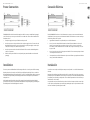
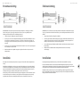
The MODAMP MODULE 1005 module comes with the required power cable for connecting to a standard Eurorack power supply
system. Follow these steps to connect power to the module. It is easier to make these connections before the module has been
mounted into a rack case.
1. Turn the power supply or rack case power o and disconnect the power cable.
2. Insert the 16-pin connector on the power cable into the socket on the power supply or rack case. The connector has a tab
that will align with the gap in the socket, so it cannot be inserted incorrectly. If the power supply does not have a keyed
socket, be sure to orient pin 1 (-12 V) with the red stripe on the cable.
3. Insert the 10-pin connector into the socket on the back of the module. The connector has a tab that will align with the
socket for correct orientation.
4. After both ends of the power cable have been securely attached, you may mount the module in a case and turn on the
power supply.
El módulo MODAMP MODULE 1005 viene con el cable de alimentación necesario para conectarse a un sistema de alimentación
estándar Eurorack. Siga estos pasos para conectar la alimentación al módulo. Es más fácil realizar estas conexiones antes de que
el módulo se haya montado en una caja de rack.
1. Apague la fuente de alimentación o la caja del bastidor y desconecte el cable de alimentación.
2. Inserte el conector de 16 clavijas del cable de alimentación en la toma de la fuente de alimentación o en la caja del
bastidor. El conector tiene una pestaña que se alineará con el espacio en el zócalo, por lo que no se puede insertar
incorrectamente. Si la fuente de alimentación no tiene un enchufe con llave, asegúrese de orientar el pin 1 (-12 V) con la
raya roja en el cable.
3. Inserte el conector de 10 pines en el zócalo en la parte posterior del módulo. El conector tiene una pestaña que se alineará
con el enchufe para una orientación correcta.
4. Una vez que ambos extremos del cable de alimentación se hayan conectado de forma segura, puede montar el módulo en
una caja y encender la fuente de alimentación.
The necessary screws are included with the module for mounting in a Eurorack case. Connect the power cable before mounting.
Depending on the rack case, there may be a series of xed holes spaced 2 HP apart along the length of the case, or a track that
allows individual threaded plates to slide along the length of the case. The free-moving threaded plates allow precise positioning
of the module, but each plate should be positioned in the approximate relation to the mounting holes in your module before
attaching the screws.
Hold the module against the Eurorack rails so that each of the mounting holes are aligned with a threaded rail or threaded
plate. Attach the screws part way to start, which will allow small adjustments to the positioning while you get them all aligned.
After the nal position has been established, tighten the screws down.
Los tornillos necesarios se incluyen con el módulo para su montaje en una caja Eurorack. Conecte el cable de alimentación antes
del montaje.
Dependiendo de la caja del bastidor, puede haber una serie de oricios jos separados 2 HP a lo largo de la caja, o una pista que
permita que las placas roscadas individuales se deslicen a lo largo de la caja. Las placas roscadas de movimiento libre permiten un
posicionamiento preciso del módulo, pero cada placa debe colocarse en una relación aproximada con los oricios de montaje en
su módulo antes de colocar los tornillos.
Sostenga el módulo contra los rieles Eurorack de modo que cada uno de los oricios de montaje esté alineado con un riel o placa
roscada. Coloque los tornillos parcialmente para comenzar, lo que permitirá pequeños ajustes en la posición mientras los alinea
todos. Una vez establecida la posición nal, apriete los tornillos.

Connexion Électrique Netzanschluss
Installation Installation
Le module MODAMP MODULE 1005 est livré avec le câble d’alimentation requis pour la connexion à un système d’alimentation standard
Eurorack. Suivez ces étapes pour connecter l’alimentation au module. Il est plus facile d’eectuer ces connexions avant que le module
n’ait été monté dans un boîtier en rack.
1. Mettez le bloc d’alimentation ou le boîtier de rack hors tension et débranchez le câble d’alimentation.
2. Insérez le connecteur à 16 broches du câble d’alimentation dans la prise du bloc d’alimentation ou du boîtier du rack. Le connecteur
a une languette qui s’alignera avec l’espace dans la prise, de sorte qu’il ne peut pas être inséré de manière incorrecte. Si le bloc
d’alimentation n’a pas de prise à clé, veillez à orienter la broche 1 (-12 V) avec la bande rouge sur le câble.
3. Insérez le connecteur à 10 broches dans la prise à l’arrière du module. Le connecteur a une languette qui s’alignera avec la prise
pour une orientation correcte.
4. Une fois que les deux extrémités du câble d’alimentation ont été solidement xées, vous pouvez monter le module dans un boîtier
et allumer l’alimentation.
Das Modul MODAMP MODULE 1005 wird mit dem erforderlichen Netzkabel für den Anschluss an ein Standard-Eurorack-
Stromversorgungssystem geliefert. Befolgen Sie diese Schritte, um das Modul mit Strom zu versorgen. Es ist einfacher, diese
Verbindungen herzustellen, bevor das Modul in ein Rackgehäuse eingebaut wurde.
1. Schalten Sie das Netzteil oder das Rackgehäuse aus und ziehen Sie das Netzkabel ab.
2. Stecken Sie den 16-poligen Stecker am Netzkabel in die Buchse am Netzteil oder im Rack-Gehäuse. Der Anschluss verfügt
über eine Lasche, die an der Lücke in der Buchse ausgerichtet ist, sodass sie nicht falsch eingesetzt werden kann. Wenn das
Netzteil keine Schlüsselbuchse hat, achten Sie darauf, Pin 1 (-12 V) mit dem roten Streifen am Kabel auszurichten.
3. Stecken Sie den 10-poligen Stecker in die Buchse auf der Rückseite des Moduls. Der Anschluss verfügt über eine Lasche, die
zur korrekten Ausrichtung an der Buchse ausgerichtet wird.
4. Nachdem beide Enden des Netzkabels fest angeschlossen wurden, können Sie das Modul in einem Gehäuse montieren und
die Stromversorgung einschalten.
Les vis nécessaires sont incluses avec le module pour le montage dans un boîtier Eurorack. Connectez le câble d’alimentation
avant le montage.
Selon le cas de rack, il peut y avoir une série de trous xes espacés de 2 HP sur la longueur du cas, ou une piste qui permet aux
plaques letées individuelles de glisser le long de la longueur du cas. Les plaques letées à déplacement libre permettent un
positionnement précis du module, mais chaque plaque doit être positionnée approximativement par rapport aux trous de
montage de votre module avant de xer les vis.
Maintenez le module contre les rails Eurorack de sorte que chacun des trous de montage soit aligné avec un rail leté ou une
plaque letée. Fixez les vis partiellement pour commencer, ce qui permettra de petits ajustements au positionnement pendant
que vous les alignerez tous. Une fois la position nale établie, serrez les vis vers le bas.
Die erforderlichen Schrauben sind im Lieferumfang des Moduls für die Montage in einem Eurorack-Gehäuse enthalten. Schließen Sie
das Netzkabel vor der Montage an.
Abhängig vom Rack-Gehäuse kann es eine Reihe von festen Löchern geben, die entlang der Länge des Gehäuses 2 PS voneinander
entfernt sind, oder eine Schiene, mit der einzelne Gewindeplatten entlang der Länge des Gehäuses gleiten können. Die frei
beweglichen Gewindeplatten ermöglichen eine präzise Positionierung des Moduls. Jede Platte sollte jedoch in der ungefähren
Beziehung zu den Befestigungslöchern in Ihrem Modul positioniert werden, bevor Sie die Schrauben anbringen.
Halten Sie das Modul so gegen die Eurorack-Schienen, dass jedes der Befestigungslöcher mit einer Gewindeschiene oder einer
Gewindeplatte ausgerichtet ist. Bringen Sie die Schrauben teilweise an, um zu beginnen. Dadurch können Sie die Position geringfügig
anpassen, während Sie alle ausrichten. Ziehen Sie die Schrauben fest, nachdem die endgültige Position festgelegt wurde.
16 17Quick Start GuideMODAMP MODULE 1005

18 19Quick Start GuideMODAMP MODULE 1005
Conexão de Força Connessione di Alimentazione
Instalação Installazione
O módulo MODAMP MODULE 1005 vem com o cabo de alimentação necessário para conectar a um sistema de fonte de
alimentação Eurorack padrão. Siga estas etapas para conectar a alimentação ao módulo. É mais fácil fazer essas conexões antes
que o módulo seja montado em um gabinete de rack.
1. Desligue a fonte de alimentação ou o gabinete do rack e desconecte o cabo de alimentação.
2. Insira o conector de 16 pinos do cabo de alimentação no soquete da fonte de alimentação ou no gabinete do rack. O
conector tem uma aba que se alinhará com a lacuna no soquete, portanto, não pode ser inserido incorretamente. Se a
fonte de alimentação não tiver um soquete chaveado, certique-se de orientar o pino 1 (-12 V) com a faixa vermelha no
cabo.
3. Insira o conector de 10 pinos no soquete na parte traseira do módulo. O conector possui uma guia que se alinha ao soquete
para orientação correta.
4. Depois que ambas as extremidades do cabo de alimentação forem conectadas com segurança, você pode montar o módulo
em uma caixa e ligar a fonte de alimentação.
Il modulo MODAMP MODULE 1005 viene fornito con il cavo di alimentazione necessario per il collegamento a un sistema di
alimentazione Eurorack standard. Seguire questi passaggi per collegare l’alimentazione al modulo. È più facile eettuare questi
collegamenti prima che il modulo sia stato montato in un case rack.
1. Spegnere l’alimentatore o il case del rack e scollegare il cavo di alimentazione.
2. Inserire il connettore a 16 pin del cavo di alimentazione nella presa sull’alimentatore o sulla custodia del rack. Il
connettore ha una linguetta che si allineerà con lo spazio nella presa, quindi non può essere inserito in modo errato. Se
l’alimentatore non dispone di una presa con chiave, assicurarsi di orientare il pin 1 (-12 V) con la striscia rossa sul cavo.
3. Inserire il connettore a 10 pin nella presa sul retro del modulo. Il connettore ha una linguetta che si allineerà con la presa
per un corretto orientamento.
4. Dopo che entrambe le estremità del cavo di alimentazione sono state ssate saldamente, è possibile montare il modulo in
una custodia e accendere l’alimentatore.
Os parafusos necessários estão incluídos com o módulo para montagem em uma caixa Eurorack. Conecte o cabo de alimentação
antes da montagem.
Dependendo da caixa do rack, pode haver uma série de orifícios xos espaçados de 2 HP ao longo do comprimento da caixa,
ou uma trilha que permite que placas roscadas individuais deslizem ao longo do comprimento da caixa. As placas roscadas
de movimento livre permitem o posicionamento preciso do módulo, mas cada placa deve ser posicionada em uma relação
aproximada com os orifícios de montagem em seu módulo antes de prender os parafusos.
Segure o módulo contra os trilhos Eurorack de forma que cada um dos orifícios de montagem quem alinhados com um trilho
ou placa rosqueada. Prenda os parafusos parcialmente para começar, o que permitirá pequenos ajustes no posicionamento
enquanto você os alinha. Depois de estabelecida a posição nal, aperte os parafusos.
Le viti necessarie sono incluse con il modulo per il montaggio in una custodia Eurorack. Collegare il cavo di alimentazione prima
del montaggio.
A seconda del case del rack, potrebbero esserci una serie di fori ssi distanziati di 2 HP l’uno dall’altro lungo la lunghezza
del case, o un binario che consente alle singole piastre lettate di scorrere lungo la lunghezza del case. Le piastre lettate a
movimento libero consentono un posizionamento preciso del modulo, ma ciascuna piastra deve essere posizionata in relazione
approssimativa con i fori di montaggio nel modulo prima di ssare le viti.
Tenere il modulo contro le guide Eurorack in modo che ciascuno dei fori di montaggio sia allineato con una guida lettata o
una piastra lettata. Attacca le viti in parte per iniziare, il che consentirà piccoli aggiustamenti al posizionamento mentre le fai
allineare tutte. Dopo aver stabilito la posizione nale, serrare le viti.

20 21Quick Start GuideMODAMP MODULE 1005
Stroomaansluiting
Strömanslutning
Installatie Installation
De MODAMP MODULE 1005-module wordt geleverd met de benodigde voedingskabel voor aansluiting op een standaard
Eurorack-voedingssysteem. Volg deze stappen om de module van stroom te voorzien. Het is gemakkelijker om deze
aansluitingen te maken voordat de module in een rekbehuizing is gemonteerd.
1. Schakel de voeding of de rekbehuizing uit en koppel de voedingskabel los.
2. Steek de 16-pins connector van de voedingskabel in de aansluiting op de voedingseenheid of rekbehuizing. De connector
heeft een lipje dat wordt uitgelijnd met de opening in de socket, zodat deze niet verkeerd kan worden geplaatst. Als
de voeding geen contactdoos met sleutel heeft, zorg er dan voor dat pin 1 (-12 V) met de rode streep op de kabel wordt
georiënteerd.
3. Steek de 10-pins connector in de aansluiting aan de achterkant van de module. De connector heeft een lipje dat uitgelijnd
is met de aansluiting voor de juiste oriëntatie.
4. Nadat beide uiteinden van de voedingskabel stevig zijn bevestigd, kunt u de module in een hoesje monteren en de
voeding inschakelen.
MODAMP MODULE 1005-modulen levereras med erforderlig strömkabel för anslutning till ett standard Eurorack-nätaggregat.
Följ dessa steg för att ansluta ström till modulen. Det är lättare att göra dessa anslutningar innan modulen har monterats i ett
rackfodral.
1. Stäng av strömmen eller rackhöljet och koppla bort strömkabeln.
2. Sätt i den 16-poliga kontakten på strömkabeln i uttaget på nätaggregatet eller rackfodralet. Kontaktdonet har en ik
som kommer i linje med springan i uttaget så att den inte kan sättas in felaktigt. Om strömförsörjningen inte har ett
nyckeluttag, se till att orientera stift 1 (-12 V) med den röda remsan på kabeln.
3. Sätt i 10-polig kontakt i uttaget på baksidan av modulen. Kontaktdonet har en ik som kommer i linje med uttaget för
korrekt orientering.
4. När båda ändarna av strömkabeln har anslutits ordentligt kan du montera modulen i ett fodral och slå på
strömförsörjningen.
De benodigde schroeven worden bij de module geleverd voor montage in een Eurorack-koer. Sluit de voedingskabel aan voor
montage.
Afhankelijk van de rackbehuizing kan er een reeks vaste gaten zijn die 2 HP uit elkaar liggen over de lengte van de behuizing, of
een rail waarmee afzonderlijke platen met schroefdraad langs de lengte van de behuizing kunnen schuiven. De vrij bewegende
plaatjes met schroefdraad maken een nauwkeurige positionering van de module mogelijk, maar elke plaat moet ongeveer in
verhouding tot de montagegaten in uw module worden geplaatst voordat u de schroeven bevestigt.
Houd de module tegen de Eurorack-rails zodat elk van de montagegaten is uitgelijnd met een rail met schroefdraad of een plaat
met schroefdraad. Bevestig de schroeven halverwege om te beginnen, waardoor kleine aanpassingen aan de positionering
mogelijk zijn terwijl u ze allemaal op één lijn krijgt. Nadat de denitieve positie is bepaald, draait u de schroeven vast.
De nödvändiga skruvarna ingår i modulen för montering i ett Eurorack-fodral. Anslut strömkabeln före montering.
Beroende på stativhöljet kan det nnas en serie fasta hål som är åtskilda 2 hk längs höljets längd eller ett spår som gör att
enskilda gängade plattor kan glida längs höljets längd. De fritt rörliga gängade plattorna möjliggör exakt placering av modulen,
men varje platta bör placeras i ungefärlig relation till monteringshålen i din modul innan skruvarna fästs.
Håll modulen mot Eurorack-skenorna så att var och en av monteringshålen ligger i linje med en gängad skena eller gängad
platta. Fäst skruvarna delvis för att börja, vilket gör det möjligt att justera små positioner medan du justerar dem alla. När den
slutliga positionen har fastställts drar du åt skruvarna.

Specications
22 23Quick Start GuideMODAMP MODULE 1005
Podłączenie Zasilania
Instalacja
Moduł MODAMP MODULE 1005 jest dostarczany z wymaganym kablem zasilającym do podłączenia do standardowego systemu
zasilania Eurorack. Wykonaj poniższe czynności, aby podłączyć zasilanie do modułu. Łatwiej jest wykonać te połączenia przed
zamontowaniem modułu w obudowie rack.
1. Wyłącz zasilacz lub obudowę szafy i odłącz kabel zasilający.
2. Włóż 16-stykowe złącze przewodu zasilającego do gniazda w zasilaczu lub w szae typu Rack. Złącze ma wypustkę, która
będzie wyrównana ze szczeliną w gnieździe, więc nie można jej nieprawidłowo włożyć. Jeśli zasilacz nie ma gniazda z
kluczem, należy zorientować styk 1 (-12 V) z czerwonym paskiem na kablu.
3. Włóż 10-pinowe złącze do gniazda z tyłu modułu. Złącze ma wypustkę, która będzie wyrównana z gniazdem, aby
zapewnić prawidłową orientację.
4. Po solidnym zamocowaniu obu końców kabla zasilającego można zamontować moduł w obudowie i włączyć zasilacz.
Do modułu dołączone są niezbędne śruby do montażu w skrzynce Eurorack. Podłącz kabel zasilający przed montażem.
W zależności od obudowy szafy może występować szereg stałych otworów rozmieszczonych w odstępach 2 HP na całej długości
obudowy lub prowadnica, która umożliwia przesuwanie pojedynczych gwintowanych płyt wzdłuż całej obudowy. Swobodnie
poruszające się gwintowane płytki umożliwiają precyzyjne ustawienie modułu, ale każda płyta powinna być ustawiona w
przybliżeniu w stosunku do otworów montażowych w module przed przykręceniem śrub.
Przytrzymaj moduł na szynach Eurorack, tak aby każdy z otworów montażowych był wyrównany z szyną gwintowaną lub
płytą gwintowaną. Wkręć śruby częściowo, aby rozpocząć, co pozwoli na drobne korekty położenia, gdy wszystkie zostaną
wyrównane. Po ustaleniu ostatecznego położenia dokręcić śruby.
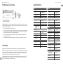
Inputs
In A / B
Type
2 x 3.5 mm TS jacks,
DC coupled
Impedance 50 kΩ, unbalanced
Max input level 10 V p-p
Gate
Type
1 x 3.5 mm TS jack,
DC coupled
Impedance 80 kΩ, unbalanced
Max input level +12 V
Minimum switching
threshold
+4 V
Mod / unmod
Type
2 x 3.5 mm TS jacks,
AC coupled
Impedance 50 kΩ, unbalanced
Max input level +12 V
Minimum switching
threshold
+4 V
CV in
Type
1 x 3.5 mm TS jack,
DC coupled
Impedance 100 kΩ, unbalanced
Max input level ±10 V
Outputs
Out
Type
1 x 3.5 mm TS jack,
DC coupled
Impedance 1 kΩ, unbalanced
Max output level 10 V p-p
CV A / B
Type
2 x 3.5 mm TS jack,
DC coupled
Impedance 400 Ω, unbalanced
CV A Max output level ±3 V
CV B Max output level ±6 V
Controls
Amplier gain -∞ to unity gain
Unmod gain -∞ to unity gain
Amp control mode
1 x sliding switch,
Exponential / linear
Unmod / mod 2 x button, LED backlit
In A / B -∞ to unity gain
Ratio ±3 V @ CV B output only
Tune
±3 V @ CV A & CV B
outputs
Power
Power supply Eurorack
Current draw
60 mA (+12 V),
45 mA (-12 V)
Physical
Standard operating
temperature range
5° C to 40° C (41° F to
104° F)
Dimensions
43 x 81 x 129 mm
(1.7 x 3.2 x 5.1")
Rack units 16 HP
Weight 0.16 kg (0.35 lbs)

FEDERAL COMMUNICATIONS COMMISSION
COMPLIANCE INFORMATION
Responsible Party Name: Music Tribe Commercial NV Inc.
Address: 5270 Procyon Street,
Las Vegas NV 89118,
United States
Phone Number: +1 702 800 8290
MODAMP MODULE 1005
This equipment has been tested and found to comply with the limits for a Class B digital
device, pursuant to part 15 of the FCC Rules. These limits are designed to provide reasonable
protection against harmful interference in a residential installation. This equipment
generates, uses and can radiate radio frequency energy and, if not installed and used in
accordance with the instructions, may cause harmful interference to radio communications.
However, there is no guarantee that interference will not occur in a particular installation. If
this equipment does cause harmful interference to radio or television reception, which can be
determined by turning the equipment o and on, the user is encouraged to try to correct the
interference by one or more of the following measures:
• • Reorient or relocate the receiving antenna.
• • Increase the separation between the equipment and receiver.
• • Connect the equipment into an outlet on a circuit dierent from that to which the receiver
is connected.
• • Consult the dealer or an experienced radio/TV technician for help.
This device complies with Part 15 of the FCC rules. Operation is subject to the following two
conditions:
(1) this device may not cause harmful interference, and
(2) this device must accept any interference received, including interference that may cause
undesired operation.
Important information:
Changes or modications to the equipment not expressly approved by Music Tribe can void the
user’s authority to use the equipment.
Hereby, Music Tribe declares that this product is in compliance with Directive 2014/30/EU,
Directive 2011/65/EU and Amendment 2015/863/EU, Directive 2012/19/EU, Regulation
519/2012 REACH SVHC and Directive 1907/2006/EC.
Full text of EU DoC is available at https://community.musictribe.com/
EU Representative: Music Tribe Brands DK A/S
Address: Ib Spang Olsens Gade 17, DK - 8200 Aarhus N, Denmark
MODAMP MODULE 1005
24 MODAMP MODULE 1005
-
 1
1
-
 2
2
-
 3
3
-
 4
4
-
 5
5
-
 6
6
-
 7
7
-
 8
8
-
 9
9
-
 10
10
-
 11
11
-
 12
12
-
 13
13


Behringer MODAMP 1005 Legendary 2500 Series Ring Modulator Guida utente
- Tipo
- Guida utente
- Questo manuale è adatto anche per
in altre lingue
- English: Behringer MODAMP 1005 Legendary 2500 Series Ring Modulator User guide
- français: Behringer MODAMP 1005 Legendary 2500 Series Ring Modulator Mode d'emploi
- español: Behringer MODAMP 1005 Legendary 2500 Series Ring Modulator Guía del usuario
- Deutsch: Behringer MODAMP 1005 Legendary 2500 Series Ring Modulator Benutzerhandbuch
- Nederlands: Behringer MODAMP 1005 Legendary 2500 Series Ring Modulator Gebruikershandleiding
- português: Behringer MODAMP 1005 Legendary 2500 Series Ring Modulator Guia de usuario
- polski: Behringer MODAMP 1005 Legendary 2500 Series Ring Modulator instrukcja
- svenska: Behringer MODAMP 1005 Legendary 2500 Series Ring Modulator Användarguide
Documenti correlati
-
Behringer 923 FILTERS Guida utente
-
Behringer 902VCA Voltage Controlled Amplifier Guida utente
-
-
 Musictribe 921B Oscillator Legendary Analog VCO Module for Eurorack Guida utente
-
-
-
-
Behringer 121 DUAL VCF Legendary Analog Dual VCF Guida utente
-
-

