ProLights 60W single source compact and zoomable LED wash luminaire Manuale utente
- Categoria
- Stroboscopi
- Tipo
- Manuale utente

USER MANUAL
MANUALE UTENTE
PIXIEWASH
WASH MOVING HEAD
EN - IT

All rights reserved by Music & Lights S.r.l. No part of this instruction manual may be
reproduced in any form or by any means for any commercial use.
In order to improve the quality of products, Music&Lights S.r.l. reserves the right to modify the
characteristics stated in this instruction manual at any time and without prior notice.
All revisions and updates are available in the ‘manuals’ section on site www.musiclights.it
REV. 03-11/18

1
PIXIEWASH
• PIXIEWASH
• Mount bracket
• Power supply cable and signal cable
• Safety rope
• User manual
Packing content
TABLE OF CONTENTS
Safety
General instructionsGeneral instructions
Warnings and installation precautionsWarnings and installation precautions
1 Technical drawing
1. 1 Operating elements and connections1. 1 Operating elements and connections
2 Installation
2. 1 Mounting2. 1 Mounting
3 Functions and settings
3. 1 Operation3. 1 Operation
3. 2 Basic3. 2 Basic
3. 3 Menu structure3. 3 Menu structure
3. 4 DMX addressing3. 4 DMX addressing
3. 5 Connection of the DMX line3. 5 Connection of the DMX line
3. 6 Construction of the DMX termination3. 6 Construction of the DMX termination
3. 7 DMX channels 3. 7 DMX channels
3. 8 DMX conguration3. 8 DMX conguration
3. 9 Autoshow 3. 9 Autoshow
3. 10 Focus adjustment3. 10 Focus adjustment
3. 11 Motor settings 3. 11 Motor settings
3. 12 Fixture settings 3. 12 Fixture settings
3. 13 Display settings 3. 13 Display settings
3. 14 Fixture test 3. 14 Fixture test
3. 15 Reset functions3. 15 Reset functions
3. 16 Fixture informations 3. 16 Fixture informations
4 Maintenance
4. 1 Maintenance and cleaning the unit4. 1 Maintenance and cleaning the unit
4. 2 Fuse replacement4. 2 Fuse replacement
4. 3 Trouble shooting4. 3 Trouble shooting
2
2
3
4
5
6
6
7
9
10
10
11
13
13
13
13
14
14
14
15
15
16
16
17

PIXIEWASH
2
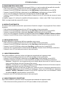
WARNING! Before carrying out any operations with the unit, carefully read this instruction
manual and keep it with cure for future reference. It contains important information about
the installation, usage and maintenance of the unit.
SAFETY
General instruction
• The products referred to in this manual conform to the European Community Directives and are there-
fore marked with .
• The unit is supplied with hazardous network voltage (230V~). Leave servicing to skilled personnel only.
Never make any modications on the unit not described in this instruction manual, otherwise you will
risk an electric shock.
• Connection must be made to a power supply system tted with ecient earthing (Class I appliance ac-
cording to standard EN 60598-1). It is, moreover, recommended to protect the supply lines of the units
from indirect contact and/or shorting to earth by using appropriately sized residual current devices.
• The connection to the main network of electric distribution must be carried out by a qualied electrical
installer. Check that the main frequency and voltage correspond to those for which the unit is designed
as given on the electrical data label.
• This unit is not for home use, only professional applications.
• Never use the xture under the following conditions:
- in places wet;
- in places subject to vibrations or bumps;
- in places with an ambient temperature of over 45°C.
• Make certain that no inammable liquids, water or metal objects enter the xture.
• Do not dismantle or modify the xture.
• All work must always be carried out by qualied technical personnel. Contact the nearest sales point for
an inspection or contact the manufacturer directly.
• If the unit is to be put out of operation denitively, take it to a local recycling
plant for a disposal which is not harmful to the environment.
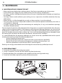
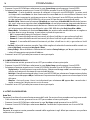
Warnings and installation precautions
• If this device will be operated in any way dierent to the one described in this manual, it may suer
damage and the guarantee becomes void. Furthermore, any other operation may lead to dangers like
short circuit, burns, electric shock, etc.
• Before starting any maintenance work or cleaning the projector, cut o power from the main supply.
• Always additionally secure the projector with the safety rope. When carrying out any work, always com-
ply scrupulously with all the regulations (particularly regarding safety) currently in force in the country
in which the xture’s being used.
• For inside use only. Not designed for outside use.
• The minimum distance between the xture and surrounding walls must be more than 50 cm and the
air vents at the housing must not be covered in any case.
• Install the xture in a well ventilated place.
• Keep any inammable material at a safe distance from the xture.
• The maximum temperature that can be reached on the external surface of the tting, in a thermally
steady state, is high. After power o, please cool down over 15 minutes.
• Shields, lenses or ultraviolet screens shall be changed if they have become damaged to such an extent
that their eectiveness is impaired.
• The lamp (LED) shall be changed if it has become damaged or thermally deformed.
• Never look directly at the light beam. Please note that fast changes in lighting, e. g. ashing light, may
trigger epileptic seizures in photosensitive persons or persons with epilepsy.

3
PIXIEWASH
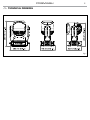
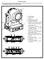
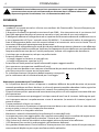
- 1 - TECHNICAL DRAWING
Fig.1

PIXIEWASH
4
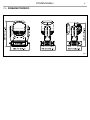
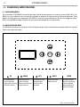
1. MOVING HEAD
2. ROTARY ARM
3. HANDLE
4. LED INDICATOR "POWER"
5. LED INDICATOR "DMX"
6. CONTROL PANEL with OLED
display and 5 button used to
access the control panel functions
and manage them.
7. POWER IN (PowerCON IN):
for connection to a socket
(100-240V~/50-60Hz) via the
supplied mains cable
8. POWER OUT (PowerCON OUT):
power output for connection of
multiple units in series.
9. MAIN FUSE HOLDER: replace a
burnt-out fuse by one of the same
type only
10. DMX IN (5-pole XLR):
1 = ground, 2 = DMX-, 3 = DMX+,
4 N/C, 5 N/C
11. DMX OUT (5-pole XLR):
1 = ground, 2 = DMX-, 3 = DMX+,
4 N/C, 5 N/C
1.1 OPERATING ELEMENTS AND CONNECTIONS
Fig.2
View A
View B
wash
4
7
9
11
10
8
6
A
2
1
B
5
3
Power
DMX
Enter

5
PIXIEWASH
- 2 - INSTALLATION
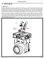
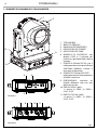
2.1 MOUNTING
The PIXIEWASH may be set up on a solid and even surface. By means of the xing facilities of the baseplate,
the unit can also be mounted upside down to a cross arm. The base plate is shown in g.3. For xing, stable
mounting clips are required. According to the gure, the bolts of the brackets are placed into the openings
provided in the base plate and turned clockwise until they lock (to the stop). Always ensure that the unit
is rmly xed to avoid vibration and slipping while operating. The mounting place must be of sucient
stability and be able to support a weight of 10 times of the unit’s weight. When carrying out any installa-
tion, always comply scrupulously with all the regulations (particularly regarding safety) currently in force
in the country in which the xture’s being used. Always additionally secure the projector with the safety
rope from falling down. For this purpose, fasten the safety rope at a suitable position so that the maximum
fall of the projector will be 20 cm.
Fig.3
CLAMP
SAFETY
CABLE
OMEGA
BRACKETS

PIXIEWASH
6
- 3 - FUNCTIONS AND SETTINGS
3.1 OPERATION
Connect the supplied main cable to a socket (100-240V~/50-60Hz). The unit will run built-in program to
reset all motors to their home position. Shortly after that the PIXIEWASH is ready for operation. To switch
o, disconnect the mains plug from the socket. For a more convenient operation it is recommended to
connect the unit to a socket which can be switched on and o via light switch.
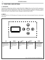
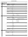
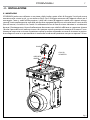
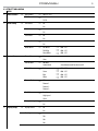
3.2 BASIC
The PIXIEWASH has a OLED display and 5 button used to access the control panel functions and manage
them (g.4).
Fig.4 - Functions of the buttons and display icons
UP DOWN LEFT RIGHT ENTER
Increases the value
displayed or passes to
the previous item in a
menu
Decreases the value
displayed or passes to
the next item in the
menu
To enter in the main
menù or to return to the
top level
Commute from units,
tens, hundred in the
menu
Conrms the displayed
value, or activates the
displayed function, or
enters the successive
menu
Enter

7
PIXIEWASH
3.3 MENU STRUCTURE
MENU
1 DMX Functions
ð
DMX Address
ð
Value (1-512)
DMX Channels
ð
13 CH
16 CH
2 Motor Setup
ð
Pan Inverse
ð
No
Yes
Tilt Inverse
ð
No
Yes
Pan Encode
ð
No
Yes
Tilt Encode
ð
No
Yes
Motor Oset
ð
Pan Oset
ð
000 - 255
Tilt Oset
ð
000 - 255
Zoom Oset
ð
000 - 255
3 System Setup Master/Slave
ð
Master
Slave
Full On Mode
ð
HB Mode
Studio Mode Auto balance mode for colors at full
White Balance
ð
Red
ð
000 - 255
Green
ð
000 - 255
Blue
ð
000 - 255
White
ð
000 - 255
Dimmer Mode
ð
O
Dimmer 1
Dimmer 2
Dimmer 3
Fan Mode
ð
Auto Speed
High Speed
Silent
Factory Setting
ð
No
Yes
4 Display Setup
ð
Display Inverse
ð
No
Yes
Back Light
ð
On
10s
20s
30s

PIXIEWASH
8
Warn Cue
ð
O
On
5 Test Setup
ð
Auto Test
ð
Manual Test
ð
Pan
ð
000 - 255
Pan Fine
ð
000 - 255
Tilt
ð
000 - 255
Tilt Fine
ð
000 - 255
Pan/Tilt Speed
ð
000 - 255
Dimmer
ð
000 - 255
Shutter
ð
000 - 255
Red
ð
000 - 255
Green
ð
000 - 255
Blue
ð
000 - 255
White
ð
000 - 255
Zoom
ð
000 - 255
6 Show setup
ð
Led Show
ð
Led Show 1
ð
Speed 000 - 255
Led Show 2
ð
Speed 000 - 255
Led Show 3
ð
Speed 000 - 255
Led Show 4
ð
Speed 000 - 255
Motor Show
ð
Motor Show 1
ð
Speed 000 - 255
Motor Show 2
ð
Speed 000 - 255
Motor Show 3
ð
Speed 000 - 255
Motor Show 4
ð
Speed 000 - 255
Zoom Adjust
ð
000 - 255
7 Reset Setup
ð
Auto Reset
ð
Manual Reset
ð
Pan Reset
ð
No
Yes
Tilt Reset
ð
No
Yes
Zoom Reset
ð
No
Yes
8 Information
ð
Fixture Time
ð
0 - 9999
Software Version
ð
DISP V 1.0; CTR - XY V 1.0
LED Temperature
ð
28°C

9
PIXIEWASH
Several units may be interconnected; follow the instructions below:
1. Connect the DMX OUT of the master unit via 5-pole XLR cable to the DMX IN of the rst slave unit.
2. Connect the DMX OUT of the rst slave unit to the DMX IN of the second slave unit, etc. until all units
are connected in a chain.
Use standard DMX cables to daisy chain your units together via the DMX connector on the rear of the
units. For longer cable runs we suggest a terminator at the last xture (see page 12).
3.4 DMX ADDRESSING
To set DMX addressing follow the instructions below:
• Press the button LEFT to enter the menu mode.
• Use the buttons UP/DOWN to select the DMX Functions item. Press the button ENTER to conrm.
• Press the buttons UP/DOWN to select the DMX Address item. Then press the button ENTER to conrm.
• Press the buttons UP/DOWN to select the desired value 001-512; Then press the button ENTER to con-
rm.
• Press repeatedly the button LEFT to return the menu mode.
To able to operate the PIXIEWASH with a light controller, adjust the DMX start address for the rst a
DMX channel. If e. g. address 33 on the controller is provided for controlling the function of the rst DMX
channel, adjust the start address 33 on the PIXIEWASH. The other functions of the light eect panel are
then automatically assigned to the following addresses.
Number of
DMX channels
Start address
(example)
DMX Address
occupied
Next possible start
address for unit No. 1
Next possible start
address for unit No. 2
Next possible start
address for unit No. 3
13 33 33-45 46 59 72
16 33 33-48 49 65 81
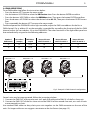
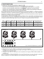
Fig.5 - Example 13 DMX channels conguration
. . . . . . . . . . . .
DMX512 Controller
DMX Address: 72DMX Address: 46DMX Address: 33 DMX Address: 59

PIXIEWASH
10
Fig.6
Fig.7
3.5 CONNECTION OF THE DMX LINE
DMX connection employs standard XLR connectors. Use shielded pair-twisted cables with 120Ω imped-
ance and low capacity.
The following diagram shows the connection mode:
ATTENTION
The screened parts of the cable (sleeve) must never be connected to the system’s earth, as this would
cause faulty xture and controller operation.
Over long runs can be necessary to insert a DMX level matching amplier.
For those connections the use of balanced microphone cable is not recommended because it cannot
transmit control DMX data reliably.
• Connect the controller DMX input to the DMX output of the rst unit.
• Connect the DMX output to the DMX input of the following unit. Connect again the output to the input
of the following unit until all the units are connected in chain.
• When the signal cable has to run longer distance is recommended to insert a DMX termination on the
last unit.
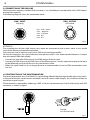
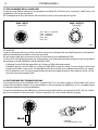
3.6 CONSTRUCTION OF THE DMX TERMINATION
The termination avoids the risk of DMX 512 signals being reected back along the cable when they reach-
es the end of the line: under certain conditions and with certain cable lengths, this could cause them to
cancel the original signals.
The termination is prepared by soldering a 120Ω 1/4 W resistor between pins 2 and 3 of the 5-pin male XLR
connector, as shown in gure.
DMX - OUTPUT
XLR socket
DMX - INPUT
XLR plug
Pin1 : GND - Shield
Pin2 : - Negative
Pin3 : + Positive
Pin4 : N/C
Pin5 : N/C
Example:
3 pin XLR connector

11
PIXIEWASH
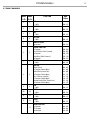
3.7 DMX CHANNELS
MODE MODE
FUNCTION DMX
Value
13 Ch 16 Ch
1 1
PAN
0~100% 000 - 255
2 2
PAN FINE
0~100% 000 - 255
3 3
TILT
0~100% 000 - 255
4 4
TILT FINE
0~100% 000 - 255
5 5
PAN/TILT SPEED
Fast to slow 000 - 255
6 6
SPECIAL FUNCTION
No Function
Pan & Tilit Reset (Hold 3 second)
No Function
Zoom Reset (Hold 3 Seconds)
No Function
000 - 049
050 - 099
100 - 149
150 - 199
200 - 255
7 7
DIMMER
0~100% 000 - 255
8 8
SHUTTER
Shutter Closed
No Function (Shutter Open)
Strobe Eect (Slow to Fast)
No Function (Shutter Open)
Pulse - Eect in sequences
No Function (Shutter Open)
Random Strobe Eect (Slow to Fast)
No Function (Shutter Open)
000 - 031
032 - 063
064 - 095
096 - 127
128 - 159
160 - 191
192 - 223
224 - 255
9 9
RED
0~100% 000 - 255
10 10
GREEN
0~100% 000 - 255
11 11
BLUE
0~100% 000 - 255
12 12
WHITE
0~100% 000 - 255
13
COLOR FUNCTION
No Function
CTC Function
Forward Spin
000 - 019
020 - 039
040 - 059

PIXIEWASH
12
MODE MODE
FUNCTION DMX
Value
13 Ch 16 Ch
13
Reverse Spin
Continuos
TBD
060 - 079
080 - 099
100 - 255
14
COLOR
Color Temperature Correction 2000K --> 3000K
White 3200 K
White 4200 K
White 5600 K
White 8000 K
FORWARD SPIN
Rainbow Eect (Slow to Fast)
REVERSE SPIN
Rainbow Eect (Slow to Fast)
CONTINUOS
Black
Red
Green
Blue
White
Red=0; Green ->Up; Blue=Full; White=0
Red=0; Green =Full; Blue->Down; White=0
Red->Up; Green=Full; Blue=0; White=0
Red=Full; Green ->Down; Blue=0; White=0
Red=Full; Green=0; Blue->Up; White=0
Red->Down; Green=0; Blue=Full; White=0
000 - 223
224 - 231
232 - 239
240 - 247
248 - 255
000 - 255
000 - 255
000 - 000
001 - 001
002 - 002
003 - 003
004 - 004
005 - 046
047 - 088
089 - 130
131 - 172
173 - 214
215 - 255
13 15
ZOOM
0~100% 000 - 255
16
DIMMER MODE
Preset Dimmer Speed from Display Menù
Dimmer Speed Mode O
Dimmer Speed Mode 1 (Fast Speed)
Dimmer Speed Mode 2 (Middle Speed)
Dimmer Speed Mode 3 (Slow Speed)
000 - 051
052 - 101
102 - 152
153 - 203
204 - 255

13
PIXIEWASH
3.8 DMX CONFIGURATION
The PIXIEWASH has 2 DMX channels congurations selectable through the control panel.
• Press the button LEFT to enter the menu mode.
• Use the buttons UP/DOWN to select the DMX Functions item. Press the button ENTER to conrm.
• Press the buttons UP/DOWN to select the DMX Channels item. Then press the button ENTER to conrm.
• Press the buttons UP/DOWN to select the desired conguration 13CH - 16CH. ; Then press the button
ENTER to save.
• Press repeatedly the button LEFT to return the menu mode.
The tables on page 13 indicate the operating mode and DMX value. The PIXIEWASH is equipped with
5-pole XLR connections.
3.9 AUTOSHOW
To enter in the automatic mode and allow to the unit to carry out its show program independently follow
the instructions below:
• Press the button LEFT to enter the menu mode.
• Use the buttons UP/DOWN to select the Show setup item. Press the button ENTER.
• Press the buttons UP/DOWN to select the Show Mode item. Then press the button ENTER to conrm.
• Press the buttons UP/DOWN to select the desired program LedShow1 - LedShow2 - LedShow3 - LedShow4;
Then press the button ENTER to save.
• Press repeatedly the button LEFT to return the menu mode.
3.10 FOCUS ADJUSTMENT
To set the focus regulation follow the instructions below:
• Press the button LEFT to enter the menu mode.
• Use the buttons UP/DOWN to select the Show setup item. Press the button ENTER.
• Press the buttons UP/DOWN to select the Focus adjust item. Then press the button ENTER to conrm.
• Press the buttons UP/DOWN to select the desired values (000-255); Then press the button ENTER to save.
• Press repeatedly the button LEFT to return the menu mode.
3.11 MOTOR SETTINGS
To change the unit parameters follow the instructions below:
• Press the button LEFT to enter the menu mode.
• Use the buttons UP/DOWN to select the Motor Setup item. Press the button ENTER.
• Press the buttons UP/DOWN to select the desired option item and press the button ENTER to conrm:
- Pan Inverse - Used for reversing Pan movement. Select Pan Inverse, press ENTER button to conrm,
present mode will blink on the display, use UP/DOWN button to select No (normal) or Yes (pan
inverse), press ENTER button to store.
- Tilt Inverse - Used for reversing tilt movement. Select Tilt Inverse, press ENTER button to conrm, present
mode will blink on the display, use UP/DOWN button to select No (normal) or Yes (tilt inverse), press
ENTER button to store.
• Motor Oset - Allows you to set an oset for the pan/tilt motor. After selecting Motor Setup function press
button ENTER to conrm. Use the buttons UP/DOWN to select Pan Oset - Tilt Oset - Zoom Oset
• Press repeatedly the button LEFT to return the menu mode.

PIXIEWASH
14
3.12 FIXTURE SETTINGS
You can change the parameters for the device by following these steps:
• Press the button LEFT to enter the menu mode.
• Use the buttons UP/DOWN to select the System setup item. Press the button ENTER to conrm.
• Press the buttons UP/DOWN to select the desired option item and press the button ENTER to conrm:
- Master/Slave - This conguration allows to connect many units PIXIEWASH. The rst will be set as
Master and the others will work as Slave with the same eect. Press the buttons UP/DOWN to set the
units as master or slave. Press the button ENTER to conrm. Use PIXIEWASH DMX connectors and
XLR cable to do a units chain.
- Full On Mode - Select the Full on Mode function to set the HB Mode (High Brightness Mode, with the
maxinum value of the colors) or Studio Mode with a automatic white balance.
- White Balance - White Balance function. Select the White Balance function to set the white balance by
changing the values (125-255) of the colors Red, Green, Blue and White.
- Dimmer Mode - Adjusting the dimmer. Enter in Dimmer Mode to select specic dimming curve.
Particularly when set:
• O: The increase in light intensity is linear
• Dimmer 1: Light intensity control is nger at low levels and coarse at high levels.
• Dimmer 2: Light intensity control is nger at high levels and coarse at low levels.
• Dimmer 3: Light intensity control is nger at low levels and high levels and coarse at medium levels.
- Fan Mode - Fan speed. Select the desired fan speed High Speed, Auto Speed or Silent through the button
UP/ DOWN.
- Factory Settings - Factory reset. Select Factory Settings function and then Yes to restore all values to the
original factory settings.
• Press repeatedly the button LEFT to return the menu mode.
3.13 DISPLAY SETTINGS
• Press the button LEFT to enter the menu mode.
• Press the buttons UP/DOWN to select the Display setup item. Then press the button ENTER.
• Press the buttons UP/DOWN to select the desired option item and press the button ENTER to conrm:
- Display Inverse - Used for reversing display. Select Display Inverse, press ENTER button to conrm, present
mode will blink on the display, use UP/DOWN button to select No (normal display) or Yes (inverse dis-
play), press ENTER button to store.
- Back Light - Display backlight. Select Back Light, press ENTER button to conrm. Use the UP/DOWN keys
to select On for display always on or Off for setting display o one minute after the exit from the menu.
- Warn Cue - Select Warn Cue, press ENTER button to conrm, present mode will blink on the display, use
UP/DOWN button to select O (Normal) or On (display will show the error warning when the unit
went wrong).
• Press repeatedly the button LEFT to return the menu mode.
3.14 FIXTURE TEST
Auto Test
Allow checking the proper functioning of the unit. Start the automatic test in the following way:
• Press the button LEFT to enter the menu mode.
• Use the buttons UP/DOWN to select the Test Setup item. Press the button ENTER to conrm.
• Press the buttons UP/DOWN to select the Auto Test item.
• To conrm and start the automatic test press the ENTER button.

15
PIXIEWASH
Manual Test
It allows to do adjustments on the eects through comands pannel to obtain a perfect balance between
the projectors.
• Press the button LEFT to enter the menu mode.
• Press the buttons UP/DOWN to select the item Test Setup. Then press the button ENTER.
• Press the buttons UP/DOWN to select the Manual Test item. Then press the button ENTER.
• Select the eect you want change (Pan, Pan Fine, Tilt, Tilt Fine, P/T Speed, Dimmer, Shutter, Red, Green, Blue, White,
Prism, Rprism, Focus).Then press the button ENTER to conrm
• Use the directional buttons to calibrate the eect setting a value between 0 - 255. Then press the but-
ton ENTER to conrm
• Press repeatedly the button LEFT to return the menu mode.
3.15 RESET FUNCTIONS
Manual reset
• Press the button LEFT to enter the menu mode.
• Press the buttons UP/DOWN to select the item Reset Setup. Then press the button ENTER.
• Press the buttons UP/DOWN to select the item Manual reset. Then press the button ENTER to conrm.
• Press the buttons UP/DOWN to select the function you want reset between Pan, Tilt, Focus. In this way
selecting Yes it is possible to start a preset program to restore the selected function.
• Then press the button ENTER to conrm, waiting the reactivation of the function.
3.16 FIXTURE INFORMATION
• Press the button LEFT to enter the menu mode.
• Press the buttons UP/DOWN to select the item Information. Then press the button ENTER.
• Press the buttons UP/DOWN to select the desired option item and press the button ENTER to conrm:
- Fixture Time - Through the Fixture Time function you can display the operating time of the projector.
- Software Version - Select Software Version, press ENTER button to conrm, rmware version will show on
the display.
- Temperature - Through the function Temperature can be displayed on the display the temperature of
the device in °C.
• Press repeatedly the button LEFT to return the menu mode.

PIXIEWASH
16
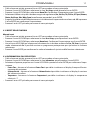
- 4 - MAINTENANCE
4.1 MAINTENANCE AND CLEANING THE UNIT
• Make sure the area below the installation place is free from unwanted persons during setup.
• Switch o the unit, unplug the main cable and wait until the unit has cooled down.
• All screws used for installing the device and any of its parts should be tightly fastened and should not
be corroded.
• Housings, xations and installation spots (ceiling, trusses, suspensions) should be totally free from any
deformation.
• When the lens is visibly damaged due to cracks or deep scratches, it must be replaced.
• The main cables must be in impeccable condition and should be replaced immediately even when a
small problem is detected.
• In order to protect the device from overheating the cooling fans (if any), and ventilation openings
should be cleaned monthly.
To ensure optimal operation and performance for a long time it is essential to periodically clean the parts
subject to dust and grease deposits. The frequency with which the following operations are to be carried
out depends on various factors, such as the amount of the eects and the quality of the working environ-
ment (air humidity, presence of dust, salinity, etc.). Use a soft cloth dampened with any detergent liquid
for cleaning glass to remove the dirt from the reectors, from the lenses and lters.
It is recommended that the projector undergoes an annual service by a qualied technician for special
maintenance involving at least the following operations:
- General cleaning of internal parts..
- Restoring lubrication of all parts subject to friction, using lubricants specically.
- General visual check of the internal components, cabling, mechanical parts, etc.
- Electrical, photometric and functional checks; eventual repairs.
Warning: we strongly recommend internal cleaning to be carried out by qualied personnel!
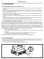
4.2 FUSE REPLACEMENT
1. Disconnect this product from the power outlet.
2. Using a screwdriver, unscrew the fuse holder cap from the housing.
3. Remove the blown fuse and replace with a good fuse of the same type and rating.
4. Screw the fuse holder cap back in place and reconnect power.
Fig.8

17
PIXIEWASH
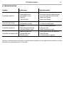
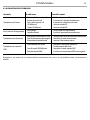
4.3 TROUBLESHOOTING
Problems Possible causes Checks and remedies
Fixture does not light up
• No mains supply
• Dimmer fader set to 0
• All color faders set to 0
• Faulty LED
• Faulty LED board
• Check the power supply voltage
• Increase the value of the dimmer channels
• Increase the value of the color channels
• Replace the LED board
• Replace the LED board
General low light intensity
• Dirty lens assembly
• Misaligned lens assembly
• Clean the xture regularly
• Install lens assembly properly
Fixture does not power up
• No power
• Loose or damaged power cord
• Faulty internal power supply
• Check for power on power outlet
• Check power cord
• Replace internal power supply
Fixture does not respond to DMX
• Wrong DMX addressing
• Damaged DMX cables
• Bouncing signals
• Check control panel and unit addressing
• Check DMX cables
• Install terminator as suggested
Contact an authorized service center in case of technical problems or not reported in the table can not be
resolved by the procedure given in the table.

PIXIEWASH
2
Music & Lights S.r.l. si riserva ogni diritto di elaborazione in qualsiasi forma delle presenti istruzioni per l’uso.
La riproduzione - anche parziale - per propri scopi commerciali è vietata.
Al ne di migliorare la qualità dei prodotti, la Music&Lights S.r.l. si riserva la facoltà di modicare, in
qualunque momento e senza preavviso, le speciche menzionate nel presente manuale di istruzioni.
Tutte le revisioni e gli aggiornamenti sono disponibili nella sezione 'Manuali' sul sito www.musiclights.it
La pagina sta caricando ...
La pagina sta caricando ...
La pagina sta caricando ...
La pagina sta caricando ...
La pagina sta caricando ...
La pagina sta caricando ...
La pagina sta caricando ...
La pagina sta caricando ...
La pagina sta caricando ...
La pagina sta caricando ...
La pagina sta caricando ...
La pagina sta caricando ...
La pagina sta caricando ...
La pagina sta caricando ...
La pagina sta caricando ...
La pagina sta caricando ...
La pagina sta caricando ...
La pagina sta caricando ...
La pagina sta caricando ...
La pagina sta caricando ...
-
 1
1
-
 2
2
-
 3
3
-
 4
4
-
 5
5
-
 6
6
-
 7
7
-
 8
8
-
 9
9
-
 10
10
-
 11
11
-
 12
12
-
 13
13
-
 14
14
-
 15
15
-
 16
16
-
 17
17
-
 18
18
-
 19
19
-
 20
20
-
 21
21
-
 22
22
-
 23
23
-
 24
24
-
 25
25
-
 26
26
-
 27
27
-
 28
28
-
 29
29
-
 30
30
-
 31
31
-
 32
32
-
 33
33
-
 34
34
-
 35
35
-
 36
36
-
 37
37
-
 38
38
-
 39
39
-
 40
40


ProLights 60W single source compact and zoomable LED wash luminaire Manuale utente
- Categoria
- Stroboscopi
- Tipo
- Manuale utente
in altre lingue
Documenti correlati
-
ProLights 60 W single source compact and zoomable LED wash luminaire Manuale utente
-
-
-
-
-
-
-