
4
e
w
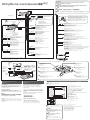
How to install the unit/ä‡Í ÒÏÓÌÚËÓ‚‡Ú¸ ÔË·Ó/ /
Installation/åÓÌÚ‡Ê/ /
Mounting collar q insertion. Bend mounting tabs.
ÇÒÚ‡‚ÎÂÌË ÏÓÌÚ‡ÊÌÓÈ ‡Ï˚ q.ᇄ˷‡˛Ú ÏÓÌÚ‡ÊÌ˚ ·ÔÍË.
q
q
Connection of power connector y
èÓ‰ÒÓ‰ËÌÂÌË ÒËÎÓ‚Ó„Ó ‡Á˙Âχ y
y
y
5
Tr im plate u mounting
ìÒÚ‡Ìӂ͇ Ó·‡ÏÎÂÌËfl u
u
u
6
Battery cable reconnection
èÓ‚ÚÓÌÓ ÔÓ‰ÒÓ‰ËÌÂÌË ͇·ÂÎfl Í ·‡Ú‡ÂÂ
How to remove the unit/ä‡Í ÒÌflÚ¸ ÔË·Ó/
/
Cautions
● Wear gloves for safety.
●
Make sure that wiring is completed
before installation.
ÇÌËχÌËÂ
● ëΉÛÂÚ Ì‡‰ÂÚ¸ Ô˜‡ÚÍË ‰Îfl
·ÂÁÓÔ‡ÒÌÓÒÚË.
● ëΉÛÂÚ Û·Â‰ËÚ¸Òfl, ˜ÚÓ ÏÓÌÚ‡Ê
˝ÎÂÍÚÓÔÓ‚Ó‰ÓÍ Á‡‚¯ÂÌ ‰Ó
ÏÓÌڇʇ ÔË·Ó‡.
●
●
●
●
Remove the cable from the battery negative terminal.
éÚÒÓ‰ËÌfl˛Ú ͇·Âθ ÓÚ ÓÚˈ‡ÚÂθÌÓ„Ó ‚˚‚Ó‰‡ ·‡Ú‡ÂË.
Bend appropriate tabs to secure the unit
without backlash.
ᇄ˷‡ÌËÂÏ ÒÓÓÚ‚ÂÚÒÚ‚Û˛˘Ëı ·ÔÓÍ ÙËÍÒËÛ˛Ú
ÔË·Ó ·ÂÁ Á‡ÁÓ.
q Screw the mounting bolt w into the main unit.
w Secure to the fire wall.
e
Snap the right and left springs into each hole.
q ᇂÂÚ˚‚‡˛Ú mÓÌÚ‡ÊÌ˚È ·ÓÎÚ w ‚„·‚Ì˚È ·ÎÓÍ.
w äÂÔÎÂÌËÂ Í ÚÂÔÎÓËÁÓÎflˆËÓÌÌÓÈ Ô‡ÌÂÎË.
e
Ç‚Ó‰flÚ Ô‡‚Û˛ Ë ÎÂ‚Û˛ ÔÛÊËÌ˚ ‚ ÓÚ‚ÂÒÚËfl ÔÓ‰ ÌËı.
q w
w
e
q w
w
e
Main unit securing
äÂÔÎÂÌË „·‚ÌÓ„Ó
·ÎÓ͇
4
Securing to fire wall
äÂÔÎÂÌËÂ Í ÚÂÔÎÓËÁÓÎflˆËÓÌÌÓÈ Ô‡ÌÂÎË
Using the rear support strap
i
ë ÔÓÏÓ˘¸˛ Á‡‰ÌÂÈ ÓÔÓÌÓÈ Ô·ÌÍË
i
i
i
Using the rubber bushing
(Option)
ë ÔÓÏÓ˘¸˛ ÂÁËÌÓ‚ÓÈ ‚ÚÛÎÍË
(ÔÓ ÓÔˆËË)
3mm
Tapping screw r
ë‡ÏÓ̇ÂÁ‡˛˘ËÈ ‚ËÌÚ r
r
r
To the unit
ä ÔË·ÓÛ
To the unit
ä ÔË·ÓÛ
Rear support strap
i
ᇉÌflfl ÓÔÓ̇fl Ô·Ì͇
i
i
i
Hexagonal nut t
òÂÒÚË„‡Ì̇fl „‡È͇ t
t
t
Rear support bracket
(supplied with car)
ᇉÌËÈ ÓÔÓÌ˚È ÍÓ̯ÚÂÈÌ
(ÔÓÒÚ‡‚ÎflÂÏ˚È Ò ‡‚ÚÓÏÓ·ËÎÂÏ)
Rubber Bushing
(Option)
êÂÁËÌÓ‚‡fl ‚ÚÛÎ͇
(ÔÓ ÓÔˆËË)
Mounting Bolt w
åÓÌÚ‡ÊÌ˚È ·ÓÎÚ w
w
w
Caution
When this unit is installed in dashboard,
ensure that there is sufficient air flow
around the unit to prevent damage from
overheating, do not block any ventilation
holes on the unit.
ÇÌËχÌËÂ
èË ÏÓÌڇʠ̇ÒÚÓfl˘Â„Ó ÛÒÚÓÈÒÚ‚‡ ̇ Ô‡ÌÂθ
ÔË·ÓÓ‚ ÒΉÛÂÚ Ó·ÂÒÔ˜ËÚ¸ ‰ÓÒÚ‡ÚÓ˜Ì˚È ÔÓÚÓÍ
‚ÓÁ‰Ûı‡ ‚ÓÍÛ„ ÌÂ„Ó ‚Ó ËÁ·ÂʇÌË „Ó
ÔÓ‚ÂʉÂÌËfl ËÁ-Á‡ Ô„‚‡, Ô˘ÂÏ ÌÂ
ÒΉÛÂÚ Á‡Í˚‚‡Ú¸ ‚ÂÌÚËÎflˆËÓÌÌ˚ ÓÚ‚ÂÒÚËfl
ÛÒÚÓÈÒÚ‚‡.
Mounting Bolt w
åÓÌÚ‡ÊÌ˚È ·ÓÎÚ w
w
w
Remove the face plate.
ëÌËχ˛Ú ÎËˆÂ‚Û˛ Ô‡ÌÂθ
ÔË·Ó‡.
1
Remove the trim plate u.
ëÌËχ˛Ú Ó·‡ÏÌÂÌËÂ
u.
u.
u
2
3
Pull out the unit with
both hands.
Ç˚Ú‡ÒÍË‚‡˛Ú Ó·ÂËÏË
Û͇ÏË ÔË·Ó.
4
Clank!
1
2
3
4
4
4
5
6
q
4
Lock release
q Insert the lock cancel plate
e until you hear a click.
w Pull the main unit.
ëÌflÚË ÒÚÓÔÓÂÌËfl
q ÇÒÚ‡‚Îfl˛Ú Ô·ÒÚËÌÛ ÒÌflÚËfl
ÒÚÓÔÓÂÌËfl e ‰Ó ˘ÂΘ͇.
w TflÌËÚe „Îa‚ÌÛ˛ e‰ËÌˈÛ.
q e
w
q
e
w
0 – 30°
53 mm
182 mm
4.5 mm – 6.0 mm
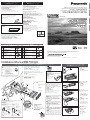
WMA MP3 CD Player/Receiver with Full Dot Matrix Display
WMA MP3 CD-ÔÎÂÂ/ÂÒË‚Â Ò ÔÓÎÌÓÒÚ¸˛ ÚӘ˜ÌÓ-χÚ˘Ì˚Ï ‰ËÒÔÎÂÂÏ
CQ-C8401W/C7401W
●Please read these instructions carefully before using this product and keep this manual for future reference.
●è‰ ̇˜‡ÎÓÏ ˝ÍÒÔÎÛ‡Ú‡ˆËË ÔÓÒËÏ ÔÓ˜ËÚ‡Ú¸ ̇ÒÚÓfl˘Û˛ ËÌÒÚÛÍˆË˛ ‚ÌËχÚÂθÌÓ Ë ı‡ÌËÚ¸  ̇ ÔÓθÁÓ‚‡ÌË ̇ ·Û‰Û˘ÂÂ.
●
●
YEFM293972A ND0205-1035 Printed in China
Matsushita Electric Industrial Co., Ltd.
Web Site : http://www.panasonic.co.jp/global/
Consult a professional for installation.
●Verify the radio using the antenna and speakers before installation.
èÓ ‚ÓÔÓÒÛ ÏÓÌڇʇ ÒΉÛÂÚ Ó·‡˘‡Ú¸Òfl Í ÒÔˆˇÎËÒÚÛ.
●è‰ ÏÓÌÚ‡ÊÓÏ ÔÓ‚Âfl˛Ú ‡‰ËÓÔËÂÏÌËÍ Ò ÔÓÏÓ˘¸˛
‡ÌÚÂÌÌ˚ Ë „ÓÏÍÓ„Ó‚ÓËÚÂÎÂÈ.
●
●
●Mounting angle side to side : horizontal
front to rear : 0 – 30°
●ì„ÓÎ ÏÓÌڇʇ ‚ ÔÓÔ˜ÌÓÈ ÔÎÓÒÍÓÒÚË : ÉÓËÁÓÌڇθ
‚ ÔÓ‰ÓθÌÓÈ ÔÎÓÒÍÓÒÚË : 0 – 30°
●
●
°
●Mounting space
●èÎÓ˘‡‰¸ ÔÓ‰ ÏÓÌÚ‡Ê
●
●
Before Installation/è‰ ÏÓÌÚ‡ÊÓÏ/
/
Before Wiring/è‰ ÏÓÌÚ‡ÊÓÏ ˝ÎÂÍÚÓÔÓ‚Ó‰ÓÍ
/
/
Supplied Hardware/ÑÂÚ‡ÎË, ‚ıÓ‰fl˘Ë ‚ ÍÓÏÔÎÂÍÚ‡ˆË˛ ÔÓÒÚ‡‚ÍË/ /
Exclusively operated with 12 V battery with
negative (–) ground.
Connect the power lead (red) very last.
Connect the battery lead (yellow) to the positive (+) terminal of
the battery or fuse block terminal (BAT).
Strip about 5 mm of the lead ends for connection.
Apply insulating tape to bare leads.
Secure loosened leads.
ꇷÓÚ‡ÂÚ ÚÓθÍÓ Ò ÔËÚ‡ÌËÂÏ ÓÚ 12 V {B} ·‡Ú‡ÂË
Ò ÓÚˈ‡ÚÂθÌÓÈ (–) ÁÂÏÎÂÈ.
èÓ‰ÒÓ‰ËÌfl˛Ú ÒËÎÓ‚ÓÈ ‚˚‚Ó‰ÌÓÈ ÔÓ‚Ó‰ (͇ÒÌ˚È) ÔÓÒΉÌËÏ.
èÓ‰ÒÓ‰ËÌfl˛Ú ‚˚‚Ó‰ÌÓÈ ÔÓ‚Ó‰ (ÊÂÎÚ˚È) Í ÔÓÎÓÊËÚÂθÌÓÏÛ (+) ‚˚‚Ó‰Û
·‡Ú‡ÂË ËÎË ÍÎÂÏÏ ·ÎÓ͇ Ô·‚ÍËı Ô‰Óı‡ÌËÚÂÎÂÈ (BAT).
ë ÍÓ̈ӂ ‚˚‚Ó‰Ì˚ı ÔÓ‚Ó‰Ó‚ ÒÌËχ˛Ú ËÁÓÎflˆË˛ ̇ ‰ÎËÌ ÓÍÓÎÓ 5
mm {ÏÏ} ‰Îfl ÒÓ‰ËÌÂÌËfl.
ç‡ Ó·Ì‡ÊÂÌÌ˚ ‚˚‚Ó‰Ì˚ ÔÓ‚Ó‰‡
̇Í·‰˚‚‡˛Ú ËÁÓÎflˆËÓÌÌÛ˛ ÎÂÌÚÛ.
îËÍÒËÛ˛Ú ÓÒ··ÎÂÌÌ˚ ‚˚‚Ó‰Ì˚ ÔÓ‚Ó‰‡.
–
EnglishêÛÒÒÍËÈ
✽ w, e and y consist of a set. (YEP0FZ5701) ✽ w, e Ë y ÒÓÒÚ‡‚Îfl˛Ú ÍÓÏÔÎÂÍÚ. (YEP0FZ5701)
✽ w, e y (YEP0FZ5701) ✽ w, e y (YEP0FZ5701)
Remove mounting collar q and trim plate u from the main
unit temporarily, which are already mounted at shipment.
ÇÂÏÂÌÌÓ ÒÌËχ˛Ú Ò „·‚ÌÓ„Ó ·ÎÓ͇ ÔË·Ó‡ ÏÓÌÚ‡ÊÌÛ˛ ‡ÏÛ q Ë
Ó·‡ÏÎÂÌË u, ÒÏÓÌÚËÓ‚‡ÌÌ˚ ÔË ÓÚ„ÛÁÍÂ.
q u
q u
(CQ-C8401W)
TEXT
Snapping point
MoÏeÌÚaθÌ˚È cÌËÏoÍ
ÔÛÌÍÚa
1
No.
Diagram
Q'ty
Item No. Diagram
Q'ty
Item
Mounting collar
åÓÌÚ‡Ê̇fl ‡Ï‡
Mounting bolt (5 mmø)
åÓÌÚ‡ÊÌ˚È ·ÓÎÚ (5 mm {ÏÏ} ø)
ø
ø
Power connector
ëËÎÓ‚ÓÈ ‡Á˙ÂÏ
Hex. Nut (5 mm ø)
òÂÒÚË„‡Ì̇fl „‡È͇ (5 mm ø)
ø
ø
Tr im plate
é·‡ÏÎÂÌËÂ
Rear support strap
ᇉÌflfl ÓÔÓ̇fl Ô·Ì͇
Tapping Screw (5 mm ø x 16 mm)
ë‡ÏÓ̇ÂÁ‡˛˘ËÈ ‚ËÌÚ (5 mm ø x 16 mm)
(5 mm ø x 16 mm)
ø x 16mm
YEFX0217222 ✽
✽
✽
✽
Lock cancel plate
è·ÒÚË̇ ÒÌflÚËfl ÒÚÓÔÓÂÌËfl
YEAJ02871
YEFG04019
1
2
1
1
1
1
1
e
w
q
q
q
w
w
YEFC05606
SRC
CQ-C8401W
SQ

L
R
Lead Connections
Connect all wires, making sure that each connection is insulated and
secure. Bundle all loose wires and fasten them with tape so they will not
fall down later. Now insert the unit into the mounting collar.
Congratulations! After making a few final checks, you’re ready to enjoy
your new auto stereo system.
èÓÍ·‰Í‡ ˝ÎÂÍÚÓÔÓ‚Ó‰ÍË
èÓ‰Ú‚Âʉ‡fl ËÁÓÎflˆË˛ Ë Ì‡‰ÂÊÌÓÒÚ¸ ‚ÒÂı ÒÓ‰ËÌÂÌËÈ, ÒÓ‰ËÌfl˛Ú ‚ÒÂ
ÔÓ‚Ó‰˚. é·‚flÁ˚‚‡˛Ú ‚Ò ҂ӷӉÌ˚ ÔÓ‚Ó‰˚ ÎÂÌÚÓÈ ‰Îfl
Ô‰ÓÚ‚‡˘ÂÌËfl Ëı ÓÚÔ‡‰ÂÌËfl. ÇÒÚ‡‚Îfl˛Ú ‡ÔÔ‡‡Ú ‚ ÏÓÌÚ‡ÊÌÛ˛ ‡ÏÛ.
Final Installation/éÍÓ̘‡ÚÂθÌ˚È ÏÓÌÚ‡Ê
/
Final Check/éÍÓ̘‡ÚÂθ̇fl ÔÓ‚Â͇
/
1. Make sure that all wires are properly connected and insulated.
2. Make sure that the main unit is securely held in the mounting collar.
3. Turn on the ignition to check the unit for proper operation.
If you have difficulties, consult your nearest authorized professional
installer for assistance.
1. ì·Âʉ‡˛ÚÒfl, ˜ÚÓ ‚Ò ÔÓ‚Ó‰˚ Ô‡‚ËθÌÓ ÒÓ‰ËÌÂÌ˚ Ë ËÁÓÎËÓ‚‡Ì˚.
2.
ì·Âʉ‡˛ÚÒfl, ˜ÚÓ ‡ÔÔ‡‡Ú ̇‰ÂÊÌÓ Á‡ÙËÍÒËÓ‚‡Ì ̇ ÏÓÌÚ‡ÊÌÓÈ ‡ÏÂ.
3. ÇÍβ˜‡˛Ú ‚˚Íβ˜‡ÚÂθ Á‡ÊË„‡ÌËfl ‰Îfl ÔÓ‚ÂÍË ÌÓχθÌÓÈ ‡·ÓÚ˚
‡ÔÔ‡‡Ú‡.
èË ‚ÓÁÌËÍÌÓ‚ÂÌËË ÔÓ·ÎÂÏ ÒΉÛÂÚ Ó·‡ÚËÚ¸Òfl Í ‡‚ÚÓËÁÓ‚‡ÌÌÓÏÛ
ÔÓÙÂÒÒËÓ̇θÌÓÏÛ ÏÓÌÚ‡ÊÌËÍÛ Á‡ ÔÓÏÓ˘¸˛.
1
3
2
FRONT SP
REAR SP
CQ-C8401W
BATTERY 15A
ACC
S
.
W-OUT
CH/AUX2-IN
CQ-C7401W
Secure the converter with screws and so forth.
Keep some distance between RCA Cords and the
antenna lead.
ìÍÂÔÎfl˛Ú ÔÂÓ·‡ÁÓ‚‡ÚÂθ ‚ËÌÚ‡ÏË Ë Ú.Ô.
é·ÂÒÔ˜˂‡˛Ú ÌÂÍÓÚÓÓ ‡ÒÒÚÓflÌË ÏÂÊ‰Û ¯ÌÛ‡ÏË RCA Ë
‡ÌÚÂÌÌ˚Ï ‚‚Ó‰ÓÏ.
AUX1-IN
CH/AUX2-IN
S
.
W-OUT
PRE-OUT REAR
PRE-OUT FRONT
Not used (Brown/white stripe)
ç ËÒÔÓθÁÛÂÚÒfl (äÓ˘Ì‚˚È Ò ·ÂÎÓÈ ÔÓÎÓÒÍÓÈ)
Antenna
ÄÌÚÂÌ̇
CQ-C8401W
AUX1-IN
VIDEO-CNT
CH/AUX2-IN
Fuse (15 A) Refer fuse replacement to your nearest authorized Panasonic
Service Center. Do not try fuse replacement by yourself.
è·‚ÍËÈ Ô‰Óı‡ÌËÚÂθ (̇ 15 Ä) ᇠÁ‡ÏÂÌÓÈ Ô·‚ÍÓ„Ó Ô‰Óı‡ÌËÚÂÎfl ÒΉÛÂÚ
Ó·‡˘‡Ú¸Òfl Í ·ÎËʇȯÂÏÛ ‡‚ÚÓËÁÓ‚‡ÌÌÓÏÛ ˆÂÌÚÛ ÚÂıÓ·ÒÎÛÊË‚‡ÌËfl «Panasonic».
çÂθÁfl Ò‡ÏÓÏÛ Ô˚Ú‡Ú¸Òfl Á‡ÏÂÌËÚ¸ Ô·‚ÍËÈ Ô‰Óı‡ÌËÚÂθ.
Wiring/åÓÌÚ‡Ê ˝ÎÂÍÚÓÔÓ‚Ó‰ÓÍ/ /
Connect as follows.
åÓÌÚËÛ˛Ú ÔÓ‚Ó‰ÍË Ú‡Í, Í‡Í ÔÓ͇Á‡ÌÓ Ì‡ ËÒ. ÌËÊÂ.
Speaker Connection/åÓÌÚ‡Ê ˝ÎÂÍÚÓÔÓ‚Ó‰ÓÍ „ÓÏÍÓ„Ó‚ÓËÚÂÎÂÈ/ /
●Do not use a 3-wire type speaker system
having a common earth lead.
●ç ÒΉÛÂÚ ÔËÏÂÌflÚ¸ ÚÂıÔÓ‚Ó‰ÌÛ˛ „ÓÏÍÓ„Ó‚ÓËÚÂθÌÛ˛ ÒËÒÚÂÏÛ,
Ëϲ˘Û˛ Ó·˘ËÈ Á‡ÁÂÏÎfl˛˘ËÈ ÔÓ‚Ó‰.
●
●
Caution
●Do not connect more than one speaker to
one set of speaker leads. (except for connecting to
a tweeter)
●Use ungrounded speakers only.
Allowable input : 60 W or more (CQ-C8401W)
: 50 W or more (CQ-C7401W)
Impedance : 4 – 8 Ω
●Distance between speaker and amplifier: 30 cm or more
●ëΉÛÂÚ ÔËÏÂÌflÚ¸ ÚÓθÍÓ ÌÂÁ‡ÁÂÏÎÂÌÌ˚ „ÓÏÍÓ„Ó‚ÓËÚÂÎË.
ÑÓÔÛÒ͇ÂÏ˚È ‚ıÓ‰: 60 W {ÇÚ} ËÎË ·ÓΠ(CQ-C8401W)
:50W{ÇÚ} ËÎË ·ÓÎÂÂ (CQ-C7401W)
àÏÔ‰‡ÌÒ: éÚ 4
– 8 Ω {éÏ}
●ê‡ÒÒÚÓflÌË ÏÂÊ‰Û „ÓÏÍÓ„Ó‚ÓËÚÂÎflÏË Ë ÛÒËÎËÚÂÎÂÏ: 30 cm ËÎË ·ÓÎÂÂ
●
●
●
– Ω
●
Front Left + (White)
è‰ÌËÈ Î‚˚È + (ÅÂÎ˚È)
Front Left – (White w/black stripe)
è‰ÌËÈ Î‚˚È
– (ÅÂÎ˚È ÔÓ‚Ó‰ Ò ˜ÂÌÓÈ ÔÓÎÓÒÍÓÈ)
–
-
+
Rear Right + (Violet)
ᇉÌËÈ Ô‡‚˚È + (îËÓÎÂÚÓ‚˚È)
Rear Right – (Violet w/black stripe)
ᇉÌËÈ Ô‡‚˚È – (îËÓÎÂÚÓ‚˚È ÔÓ‚Ó‰ Ò ˜ÂÌÓÈ ÔÓÎÓÒÍÓÈ)
–
+
-
Front Right + (Gray)
è‰ÌËÈ Ô‡‚˚È + (ëÂ˚È)
Front Right – (Gray w/black stripe)
è‰ÌËÈ Ô‡‚˚È – (ëÂ˚È ÔÓ‚Ó‰ Ò ˜ÂÌÓÈ ÔÓÎÓÒÍÓÈ)
–
+
-
Rear Left + (Green)
ᇉÌËÈ Î‚˚È + (áÂÎÂÌ˚È)
Rear Left – (Green w/black stripe)
ᇉÌËÈ Î‚˚È – (áÂÎÂÌ˚È ÔÓ‚Ó‰ Ò ˜ÂÌÓÈ ÔÓÎÓÒÍÓÈ)
–
+
-
Caution
To prevent damage to the unit, do not connect the power connector
until the whole wiring is completed.
ÇÌËχÌËÂ
ÇÓ ËÁ·ÂʇÌË ÔÓ‚ÂʉÂÌËfl ÔË·Ó‡ Ì ÒΉÛÂÚ ÔÓ‰ÒÓ‰ÂÌËflÚ¸ ÒËÎÓ‚ÓÈ ‡Á˙ÂÏ ‰Ó
ÔÓÎÌÓ„Ó Á‡‚¯ÂÌËfl ÏÓÌڇʇ ˝ÎÂÍÚÓÔÓ‚Ó‰ÓÍ.
ÇÌËχÌËÂ
●
çÂθÁfl ÔÓ‰ÒÓ‰ËÌflÚ¸ ‰‚‡ Ë ·ÓΠ„ÓÏÍÓ„Ó‚ÓËÚÂÎfl Í Ó‰ÌÓÏÛ
̇·ÓÛ ‚˚‚Ó‰Ì˚ı ÔÓ‚Ó‰Ó‚ „ÓÏÍÓ„Ó‚ÓËÚÂÎfl (Á‡ ËÒÍβ˜ÂÌËÂÏ
ÒÎÛ˜‡fl ÔÓ‰ÒÓ‰ËÌÂÌËfl Í „ÓÏÍÓ„Ó‚ÓËÚÂβ ‰Îfl
‚ÓÒÔÓËÁ‚‰ÂÌËfl ‚ÂıÌËı ˜‡ÒÚÓÚ)
●
●
Antenna
ÄÌÚÂÌ̇
Preamp Out Connector
(
Front
)
ÉÌÂÁ‰Ó ‰Îfl ÔÓ‰Íβ˜ÂÌËfl ‚˚ıÓ‰ÌÓ„Ó Í‡·ÂÎfl Ô‰ÛÒËÎËÚÂÎfl (Ô‰ÌÂÂ)
Preamp Out Connector
(
Front
)
ÉÌÂÁ‰Ó ‰Îfl ÔÓ‰Íβ˜ÂÌËfl ‚˚ıÓ‰ÌÓ„Ó Í‡·ÂÎfl Ô‰ÛÒËÎËÚÂÎfl (Ô‰ÌÂÂ)
(
R
)/(臂.)/ /(
Preamp Out Connector
(
Rear
)
ÉÌÂÁ‰Ó ‰Îfl ÔÓ‰Íβ˜ÂÌËfl ‚˚ıÓ‰ÌÓ„Ó Í‡·ÂÎfl Ô‰ÛÒËÎËÚÂÎfl (Á‡‰ÌÂÂ)
Preamp Out Connector
(
Rear
)
ÉÌÂÁ‰Ó ‰Îfl ÔÓ‰Íβ˜ÂÌËfl ‚˚ıÓ‰ÌÓ„Ó Í‡·ÂÎfl Ô‰ÛÒËÎËÚÂÎfl (Á‡‰ÌÂÂ)
(
Red
)/(
ä‡ÒÌ˚È
)/ /
Subwoofer Output Connector
The RCA cord of an external power amplifier should be
connected.
ëÓ‰ËÌËÚÂθ Í ‚˚ıÓ‰Û Ò‡·‚ÛÙ‡
ëÓ‰ËÌfl˛Ú ¯ÌÛ RCA ‚̯ÌÂ„Ó ÛÒËÎËÚÂÎfl.
Power Lead
(
ACC or IGN
)
To ACC power, +12 V DC.
(Red)/(ä‡ÒÌ˚È)/
/
ëËÎÓ‚ÓÈ ‚˚‚Ó‰ÌÓÈ ÔÓ‚Ó‰ (Äëë ËÎË IGN) ä ÔËÚ‡Ì˲ Äëë, +12 V {B} ÔÓÒÚ.Ú.
Ground Lead To a clean, bare metallic part of the car chassis.
(Black)/(óÂÌ˚È)/
/
á‡ÁÂÏÎfl˛˘ËÈ ÔÓ‚Ó‰ ä˜ËÒÚÓÈ, ӷ̇ÊÂÌÌÓÈ ÏÂÚ‡Î΢ÂÒÍÓÈ ˜‡ÒÚË ‡‚ÚÓÏÓ·ËθÌÓ„Ó ¯‡ÒÒË.
Battery Lead To the car battery, continuous +12 V DC.
(Yellow)/(ÜÂÎÚ˚È)/
/
Ç˚‚Ó‰ ·‡Ú‡ÂË ä ‡‚ÚÓÏÓ·ËθÌÓÈ ·‡Ú‡ÂÂ, ÌÂÔÂ˚‚Ì. +12 V {B} ÔÓÒÚ.Ú.
(Blue w/white stripe)/(ëËÌËÈ ÔÓ‚Ó‰ Ò ·ÂÎÓÈ ÔÓÎÓÒÍÓÈ)/
/
External Amplifier Control Power Lead To an external amplifier. (Max. 100 mA)
ëËÎÓ‚ÓÈ ‚˚‚Ó‰ÌÓÈ ÔÓ‚Ó‰ ‰Îfl ÛÔ‡‚ÎÂÌËfl ‚̯ÌËÏ ÛÒËÎËÚÂÎÂÏ ä ‚Ì¯ÌÂÏÛ ÛÒËÎËÚÂβ. (å‡ÍÒ. 100 mA {ÏÄ} )
(Blue)/(ëËÌËÈ)/
/
Motor Antenna Relay Control Lead To Motor Antenna. (Max. 100 mA)
(This lead is not intended for use with a switch actuated power antenna)
Ç˚‚Ó‰ÌÓÈ ÔÓ‚Ó‰ ÂÎÂÈÌÓ„Ó ÛÔ‡‚ÎÂÌËfl ‡ÌÚÂÌÌÓÈ Ò ÏÓÚÓÌ˚Ï ÔË‚Ó‰ÓÏ ä ‡ÌÚÂÌÌÂ Ò ÏÓÚÓÌ˚Ï ÔË‚Ó‰ÓÏ.
(å‡ÍÒ. 100 mÄ {ÏÄ})
(ùÚÓÚ ‚˚‚Ó‰ÌÓÈ ÔÓ‚Ó‰ Ì Ô‰̇Á̇˜ÂÌ ‰Îfl ÔËÏÂÌÂÌËfl Ò ‡ÌÚÂÌÌÓÈ Ò ÏÓÚÓÌ˚Ï ÔË‚Ó‰ÓÏ, ‚Íβ˜‡ÂÏÓÈ
ÔÂÂÍβ˜‡ÚÂÎÂÏ)
CD Changer/AUX Input Connector
The RCA cord of a CD changer/AUX should be connected.
ëÓ‰ËÌËÚÂθ Í ‚ıÓ‰Û CD-˜ÂÈ̉ʇ/AUX
ëÓ‰ËÌfl˛Ú ¯ÌÛ RCA CD ˜ÂÈ̉ʇ/AUX.
CD Changer/AUX Input Connector
The RCA cord of a CD changer/AUX should be connected.
ëÓ‰ËÌËÚÂθ Í ‚ıÓ‰Û CD-˜ÂÈ̉ʇ/AUX
ëÓ‰ËÌfl˛Ú ¯ÌÛ RCA CD ˜ÂÈ̉ʇ/AUX.
DC/DC Converter
èÂÓ·‡ÁÓ‚‡ÚÂθ
ÔÓÒÚÓflÌÌÓ„Ó ÚÓ͇ ‚ ÔÓÒÚÓflÌÌ˚È
(
L
)/(ã‚.)/ /
(
R
)/(臂.)/ /
(White)/(
ÅÂÎ˚È
)/ /
(
Red
)/(
ä‡ÒÌ˚È
)/ /
● CD changer, DVD changer and AUX cannot be connected at the same time.
● ç‚ÓÁÏÓÊÌÓ ÔÓ‰ÒÓ‰ËÌËÚ¸ CD-˜ÂÈ̉ÊÂ, DVD-˜ÂÈ̉ÊÂ Ë AUX Ó‰ÌÓ
●
●
(Option)
(ÔÓ ÓÔˆËË)
System Upgrade Example: Connecting with the DVD changer/
èËÏ ‡Ò¯ËÂÌËfl ÒËÒÚÂÏ˚: ëÓ‰ËÌÂÌËÂ Ò DVD-˜ÂÈ̉ÊÂÓÏ/
/
RCA Cord
òÌÛ RCA
Ground Lead
á‡ÁÂÏÎfl˛˘ËÈ ÔÓ‚Ó‰
Battery Lead
ŇڇÂÈÌ˚È ÔÓ‚Ó‰
CX-DH801W
✽
To the Hide-away Unit: CY-VM1500EX
äÒÍ˚ÚÓÏÛ ‡ÔÔ‡‡ÚÛ: CY-VM1500EX
✽ Remote-In (RCA)
ÑËÒڇ̈.-‚ıÓ‰ (RCA)
CQ-C8401W
DIN Cord
òÌÛ DIN
✽ Video Control Lead (output)
èÓ‚Ó‰ ‚ˉÂÓÛÔ‡‚ÎÂÌËfl (‚˚‚Ó‰)
✽
Video Output
ÇˉÂÓ‚˚‚Ó‰
TV Tuner/AUX Input Connector
The RCA cord of a TV Tuner/AUX should be connected.
ÉÌÂÁ‰Ó ‰Îfl ÚÂ΂ËÁËÓÌÌÓ„Ó Ú˛Ì‡/‚ıÓ‰‡ AUX
èÓ‰ÒÓ‰ËÌfl˛Ú ¯ÌÛ RCA ÚÂ΂ËÁËÓÌÌÓ„Ó Ú˛Ì‡/AUX.
Subwoofer Output Connector
The RCA cord of an external power amplifier should be
connected.
ëÓ‰ËÌËÚÂθ Í ‚˚ıÓ‰Û Ò‡·‚ÛÙ‡
ëÓ‰ËÌfl˛Ú ¯ÌÛ RCA ‚̯ÌÂ„Ó ÛÒËÎËÚÂÎfl.
(
L
)/(ã‚.)/ /
(White)/(
ÅÂÎ˚È
)/ /
(
R
)/(臂.)/ /(
(
Red
)/(
ä‡ÒÌ˚È
)/ /
(
L
)/(ã‚.)/ /
(White)/(
ÅÂÎ˚È
)/ /
(
R
)/(臂.)/ /(
(
Red
)/(
ä‡ÒÌ˚È
)/ /
(White)/(
ÅÂÎ˚È
)/ /
(
Red
)/(
ä‡ÒÌ˚È
)/ /
TV Tuner/AUX Input Connector
The RCA cord of a TV Tuner/AUX should be connected.
ÉÌÂÁ‰Ó ‰Îfl ÚÂ΂ËÁËÓÌÌÓ„Ó Ú˛Ì‡/‚ıÓ‰‡ AUX
èÓ‰ÒÓ‰ËÌfl˛Ú ¯ÌÛ RCA ÚÂ΂ËÁËÓÌÌÓ„Ó Ú˛Ì‡/AUX.
(White)/(
ÅÂÎ˚È
)/ /
(
Red
)/(
ä‡ÒÌ˚È
)/ /
(
L
)/(ã‚.)/ /
(White)/(
ÅÂÎ˚È
)/ /
(
R
)/(臂.)/ /(
(
Red
)/(
ä‡ÒÌ˚È
)/ /
(
L
)/(ã‚.)/ /
(White)/(
ÅÂÎ˚È
)/ /
(
R
)/(臂.)/ /(
(
Red
)/(
ä‡ÒÌ˚È
)/ /
(
L
)/(ã‚.)/ /
(White)/(
ÅÂÎ˚È
)/ /
(
R
)/(臂.)/ /(
(
Red
)/(
ä‡ÒÌ˚È
)/ /
(
L
)/(ã‚.)/ /
(White)/(
ÅÂÎ˚È
)/ /
(
R
)/(臂.)/ /(
(
Red
)/(
ä‡ÒÌ˚È
)/ /
(
L
)/(ã‚.)/ /
(
R
)/(臂.)/ /
(White)/(
ÅÂÎ˚È
)/ /
(
Red
)/(
ä‡ÒÌ˚È
)/ /
-
 1
1
-
 2
2


Panasonic CQ-C7401W Manuale utente
- Tipo
- Manuale utente
- Questo manuale è adatto anche per
in altre lingue
Documenti correlati
-
Panasonic CD Player CQ-C7405W Manuale utente
-
-
-
-
-
-
-
-
Panasonic CQC1123NE Istruzioni per l'uso
-