HK Audio Lucas Nano 605 FX Manuale utente
- Categoria
- Altoparlanti della soundbar
- Tipo
- Manuale utente
Questo manuale è adatto anche per

LUCAS
NANO 605 FX
MANUAL 1.1
• English • Français• Deutsch • Italiano • Español

Version 2.5 12/2016
Important Safety Instructions!
Read before connecting!
This product has been built by the manufacturer in accordance with
IEC 60065 and left the factory in safe working order. To maintain
this condition and ensure non-risk operation, the user must
follow the advice and warning comments found in the operating
instructions. If this product shall be used in vehicles, ships or
aircraft or at altitudes exceeding 2000 m above sea level, take care
of the relevant safety regulations which may exceed the IEC 60065
requirements.
WARNING: To prevent the risk of fire and shock hazard, do not
expose this appliance to moisture or rain. Do not open case – no
user serviceable parts inside. Refer service to qualified service
personnel.
This symbol, wherever it appears, alerts you to the presence
of uninsulated dangerous voltage inside the enclosure – voltage that
may be sufficient to constitute a risk of shock.
This symbol, wherever it appears, alerts you to the presence
of externally accessible hazardous voltage. External wiring connected
to any terminal marked with this symbol must be a “ready made
cable” complying with the manufacturers recommendations, or must
be a wiring installed by instructed persons only.
This symbol, wherever it appears, alerts you to important
operating and maintenance instructions in the accompanying
literature. Read the manual.
This symbol, wherever it appears, tells you: Take care! Hot
surface! To prevent burns you must not touch.
All electrical and electronic products including batteries
should be disposed of separately from the municipal waste stream
via designated collection facilities appointed by the government or
the local authorities.
• Read these instructions.
• Keep these instructions.
• Follow all warnings and instructions marked on the product and
in this manual.
• Do not use this product near water. Do not place the product near
water, baths, wash basins, kitchen sinks, wet areas, swimming
pools or damp rooms.
• Do not place objects containing liquid on the product – vases,
glasses, bottles etc.
• Clean only with dry cloth.
• Do not remove any covers or sections of the housing.
• The set operating voltage of the product must match the local
mains supply voltage. If you are not sure of the type of power
available consult your dealer or local power company.
• Before connecting the device, please ensure that the mains supply
you are using is equipped with adequate protection against short
circuiting and grounding faults when the device is plugged in.
• To reduce the risk of electrical shock, the grounding of this product
must be maintained. Use only the power supply cord provided with
this product, and maintain the function of the center (grounding)
pin of the mains connection at any time. Make sure the mains
outlet used provides a proper protective ground connection.
• Do not defeat the safety purpose of the polarized or grounding-
type plug. A polarized plug has two blades with one wider than the
other. A grounding type plug has two blades and a third grounding
prong. The wide blade or the third prong are provided for your
safety. If the provided plug does not fit into your outlet, consult an
electrician for replacement of the obolete outlet.
• Protect the power cord from being walked on or pinched
particularly at plugs, convenience receptacles, and the point where
they exit from the device! Power supply cords should always be
handled carefully. Periodically check cords for cuts or sign of
stress, especially at the plug and the point where the cord exits
the device.
• Never use a damaged power cord.
• Unplug this product during lightning storms or when unused for
long periods of time.
• This product can be fully disconnected from mains only by pulling
the mains plug at the unit or the wall socket. The product must be
placed in such a way at any time, that disconnecting from mains
is easily possible.
• Fuses: Replace with IEC127 (5x20mm) type and rated fuse for best
performance only! It is prohibited to use “patched fuses” or to
short the fuse-holder. Replacing any kind of fuses must only be
carried out by qualified service personal.
• Refer all servicing to qualified service personnel. Servicing is
required when the unit has been damaged in any way, such as:
- When the power cord or plug is damaged or frayed.
- If liquid has been spilled or objects have fallen into the product.
- If the product has been exposed to rain or moisture.
- If the product does not operate normally when the operating
instructions are followed.
- If the product has been dropped or the cabinet has been damaged.
• Do not connect external speakers to this product with an
impedance lower than the rated impedance given on the product
or in this manual. Use only cables with sufficient cross section
according to the local safety regulations.
• Keep away from direct sunlight.
• Do not install near heat sources such as radiators, heat registers,
stoves or other devices that produce heat.
• This apparatus is for moderate climates areas use, not suitable for
use in tropical climates countries.
• Do not block any ventilation openings. Install in accordance with
manufacturer’s instructions. This product must not be placed in
a built-in installation such as a rack unless proper ventilation is
provided.
• Always allow a cold device to warm up to ambient temperature,
when being moved into a room. Condensation can form inside it
and damage the product, when being used without warming up.
• Do not place naked flame sources, such as lighted candles on the
product.
• The device must be positioned at least 20 cm/8“ away from walls.
• Use only with the cart, stand, tripod, bracket or table specified by
the manufacturer or sold with the product. When a cart is used,
use caution when moving the cart/product combination to avoid
injury from tip-over.
• Use only accessories recommended by the manufacturer, this
applies for all kind of accessories, for example protective covers,
transport bags, stands, wall or ceiling mounting equipment. In
case of attaching any kind of accessories to the product, always
follow the instructions for use, provided by the manufacturer.
Never use fixing points on the product other than specified by the
manufacturer.
• This appliance is NOT suitable to be used by any person or
persons (including children) with limited physical, sensorical or
mental ability, or by persons with insufficient experience and/or
knowledge to operate such an appliance. Children under 4 years of
age must be kept away from this appliance at all times.
• Never push objects of any kind into this product through cabinet
slots as they may touch dangerous voltage points or short out
parts that could result in risk of fire or electric shock.
• This product is capable of delivering sound pressure levels in
excess of 90 dB, which may cause permanent hearing damage!
Exposure to extremely high noise levels may cause a permanent
hearing loss. Wear hearing protection if continously exposed to
such high levels.
• The manufacturer only guarantees the safety, reliability and
efficiency of this product if:
- Assembly, extension, re-adjustment, modifications or repairs are
carried out by the manufacturer or by persons authorized to do so.
- The electrical installation of the relevant area complies with the
requirements of IEC (ANSI) specifications.
- The unit is used in accordance with the operating instructions.
• This product is optimized for use with music and speech signals.
Using this product with sine wave, square wave or other kind of
measuring signals at higher level may lead to severe damage of
the product.
General Notes on Safety for Loudspeaker
Systems
Mounting systems may only be used for those loudspeaker
systems authorized by the manufacturer and only with the mounting
accessories specified by the manufacturer in the installation
instructions. Read and heed the manufacturer’s installation
instructions. The indicated load-bearing capacity cannot be
guaranteed and the manufacturer will not be liable for damages in
the event of improper installation or the use of unauthorized
mounting accessories.
The system’s load-bearing capacity cannot be guaranteed and
the manufacturer will not be liable for damages in the event that
loudspeakers, mounting accessories, and connecting and attaching
components are modified in any way.
Components affecting safety may only be repaired by the
manufacturer or authorized agents, otherwise the operating permit
will be voided.
Installation may be performed qualified personnel only, and
then only at pick-points with sufficient load-carrying capacity and in
compliance with local building regulations. Use only the mounting
hardware specified by the manufacturer in the installation
instructions (screws, anchors, etc.). Take all the precautions
necessary to ensure bolted connections and other threaded locking
devices will not loosen.
Fixed and portable installations (in this case, speakers and
mounting accessories) must be secured by two independent safeties
to prevent them from falling. Safeties must be able to catch
accessories or parts that are loose or may become loose. Ensure
compliance with the given national regulations when using
connecting, attaching, and rigging devices. Factor potential dynamic
forces (jerk) into the equation when determining the proper size and
load-bearing capacity of safeties.
Be sure to observe speaker stands’ maximum load-bearing
capacity. Note that for reasons of design and construction, most
speaker stands are approved to bear centric loads only; that is, the
speakers’ mass has to be precisely centered and balanced. Ensure
speaker stands are set up stably and securely. Take appropriate
added measures to secure speaker stands, for example when:
- the floor or ground surface does not provide a stable, secure base.
- they are extended to heights that impede stability.
- high wind pressure may be expected.
- there is the risk that they may be knocked over by people.
Special measures may become necessary as precautions against
unsafe audience behavior. Do not set up speaker stands in
evacuation routes and emergency exits. Ensure corridors are wide
enough and put proper barriers and markings in place when setting
speaker stands up in passageways. Mounting and dismounting
are especially hazardous tasks. Use aids suitable for this purpose.
Observe the given national regulations when doing so.
Wear proper protection (in particular, a helmet, gloves, and
safety shoes) and use only suitable means of ascent (ladders,
scaffolds, etc.) during installation. Compliance with this requirement
is the sole responsibility of the company performing the installation.
WARNING!
After installation, inspect the system comprised of the mounting
fixtures and loudspeakers to ensure it is properly secured.
The operator of loudspeaker systems (fixed or portable) must
regularly inspect or task a third party to regularly inspect all system
components in accordance with the given country’s regulations and
have possible defects repaired immediately.
We also strongly recommend maintaining a logbook or the like to
document all inspections.
When installing speakers for longer lasting or permanent outdoor
operation, be sure to take into account the stability and load-
bearing capacity of platforms and surfaces; loads and forces exerted
by wind, snow, and ice; as well as thermal influences. Also be sure
to provide sufficient safety margins for the rigging points used for
flown systems. Observe the given national regulations when doing
so.
• Ask the manufacturer if your product is allowed for outdoor usage !
Professional loudspeaker systems can produce harmful
volume levels. Even prolonged exposure to seemingly harmless levels
(starting at about 95 dBA SPL) can cause permanent hearing
damage! Therefore we recommend that everyone who is exposed to
high volume levels produced by loudspeaker systems wears
professional hearing protection (earplugs or earmuffs).
Manufacturer: Stamer Musikanlagen GmbH, Magdeburger Str. 8,
66606 St. Wendel, Germany

LUCAS NANO 605 FX 1.1
3
Welcome to the HK Audio family!
Thank you for choosing a brand-name product made by our company. It
was engineered and built with the greatest care so it will serve you well for
many tomorrows to come.
Even if your experience with sound systems runs deep, some things
about this product are sure to be new to you. This is why we ask that you do
not set this manual aside without reading it fi rst. Be sure to keep it in a
safe place for later reference.
Here's wishing you the best sound at every occasion!
Your HK Audio team
Strong electromagnetic interference or electrostatic discharge
may prevent the product from functioning normally. If this happens, the
product may be returned to normal operation by powering o and on
again. Should this not result in the product functioning normally again,
please move the product away from the source of disturbance and try
again.
Warranty
Use the convenient online registration option at www.hkaudio.com.
http://warranty.hkaudio.com
The registration is only valid if the device is registered within 30 days of
the date of purchase.
HK Audio
Technischer Service
Postfach 1509
66595 St. Wendel, Germany
Fax: +49 6851 905 100
1 General Info
Contents
When you fi rst unpack your LUCAS NANO 605 FX, take a quick inventory to
make sure the package comes complete with all the contents. LUCAS NANO
605 FX consists of a powered subwoofer and two satellites. A speaker pole
adapter sleeve (M33 to M20), a protective cap for the speaker pole and a
mains cable are also included, which you’ll fi nd in the box holding the power
cord.
The System's Components
The Subwoofer
The subwoofer houses the 10" woofer, the system’s active circuitry and the
Class D power amplifi ers. The speaker outputs for connecting satellites
and the mains socket are located on the rear. That’s where you’ll also fi nd
the transport bay for the satellites and a recessed Auto Sleep button that
activates an automatic power-saving function.
Speaker OutEasy-Click Signal contacts
LR
S-Connect (M33)
On top of the housing, you’ll fi nd an Easy-Click guide rail
with built-in signal-carrying terminals and an M33 pole
mount that is also able to route the signal. The M33 is
designed to take the S-CONNECT POLE LN speaker ex-
tension pole. The included adapter sleeve (M33 to M20)
lets you attach standard M20 speaker poles, but they
don't have a built-in signal bus.
LUCAS NANO 605 FX
• English • Français• Deutsch • Italiano • Español
Speaker pole adapter
sleeve (M33 to M20)

LUCAS NANO 605 FX 1.1
4
The Satellites
The two satellites are loaded with one each 4.5" broadband speaker and
a 1" horn in coaxial array. The speakers are fronted with an acoustic lens—
HKAudio's proprietary Multicell Transformer—that delivers higher sound
pressure, less distortion and enhanced directivity.
A 3/8" threaded insert on the bottom of the housing serves to mount the
satellite on a standard microphone stand. The optionally available Pole
Mount Adapter lets you mount the satellite on a standard 35 mm pole.
On the bottom of the enclosure is an Easy-Click connector with a built-in
signal bus. It lets you slot the satellites right into the subwoofer’s Easy-
Click locking mechanism. Two contacts establish an audio link with the
subwoofer, so you don't need any speaker cords to route signals.
Speaker In Signal contacts
3/8"
Easy-Click
On top of the housing is another guide rail that takes two upside down
satellites. It establishes audio and mechanical connections, and couples
the speakers acoustically to achieve even more sound pressure and greater
reach.
S-CONNECT POLE LN (optional)
The S-CONNECT POLE LN A is a freely adjustable speaker
extension pole with a built-in signal bus. It provides a
very elegant way of mounting satellites on the subwoofer
without having to use speaker cords. The S-CONNECT
POLE LN screws into the S-CONNECT insert on the
subwoofer, and the satellites snap right onto the pole's
Easy-Click connector. This also links up with the built-in
signal bus so you don't need an external cable.
Signal contacts
Easy-Click
Setting Up
Extracting the Satellites
The LUCAS NANO 605 FX satellites are locked in place in the bay on the rear
of the subwoofer. Here’s how to undo the transportation latches:
• Carefully set the subwoofer face down on the speaker front and turn the
T-grips on both sides to unlock the spring-mounted locking pins. Remove
the two satellites from the transport bay.
• Always make sure the locking pins are engaged to fi x the two satellites in
place when transporting your LUCAS NANO 605 FX.
Wireless Convenience, the Easy-Click Way
The Easy-Click connector snaps in place to physically link the two satellites;
what’s more, it also establishes an electrical connection.
•To disconnect the satellites, turn the speaker pair to the position shown
in the fi gure below, and press the top satellite—that is, the one with the
inscription that reads ‘push to release’—forward and out of the guide rail.
• The procedure is reversed 180° to lock the satellites in place. Hold the
speaker pair as shown in the diagram below and slide the top satellite—
that is, the one with the inscription that reads ‘push to connect’—forward
into the guide rail until it clicks fi rmly into place.

LUCAS NANO 605 FX 1.1
5
Wireless Setup Options with Easy-Click
Mono Cube
No cables needed
Mono System
with S-CONNECT POLE LN
No cables needed
Signal via
Easy-Click
Mono Cube
The mono cube is your simplest option for setting up LUCAS NANO 605 FX.
In this confi guration, the connected pair of satellites is mounted right on
top of the subwoofer. In this setup, the Easy-Click connector also serves to
route the signal between the subwoofer and satellite array.
• To this end, place the subwoofer upright.
• Hold the paired satellites with the speakers facing forward as shown in
the fi gure on the left. Now push on the back of the enclosures, sliding the
pair forward into the guide rail until they click fi rmly into place.
Be advised note that you will not be able to tap the system’s full audio
potential with this setup.
A Mono System with an S-CONNECT POLE LN
Another wireless setup option is the mono system with the optional
S-CONNECT POLE LN, a signal-routing speaker pole. This pole’s base end
screws straight into the M33 pole mount on the subwoofer and its top end
connects to the satellite array via Easy-Click.
Be sure to set the Setup selector to ‘Satellite Array’ when you use these
two wireless setup options (for more on this, see section
●
21
):
Setup
Your LUCAS NANO 605 FX is now ready to go.
For details on setup options (such as stereo and twin stereo systems) as
well as descriptions of the add-ons that are available for these setups, read
Chapter 4 - Setups and Accessories.
• English • Français• Deutsch • Italiano • Español

LUCAS NANO 605 FX 1.1
6
2 Connectors and Control Features
●
1
Power
This button switches LUCAS NANO 605 FX on and o .
●
2
Status Indicator
This dual-color LED indicates the following statuses:
• Green = power on
• Red = limit/mute or error
If it fl ashes briefl y red from time to time, this tells you that the limiter is
responding to signal peaks.
Heads up! If the Status LED stays red while LUCAS NANO 605 FX is
up and running, the system is being overloaded. Turn down the signal
level! If you are not feeding a signal in and the Status LED stays red, a
malfunction has occurred.
Note: There are situations when LUCAS NANO 605 FX remains muted
for about two seconds to give the amplifi er unit time to ramp up and to
prevent switching noise (the Status LED lights up red during this time).
It does this:
• when you press the Power button to switch the system on
• when you press the Setup button
If the light remains on, a malfunction has occurred and you need to get in
touch with our Technical Service team.
●
3
Bluetooth Indicator
This indicator lights up blue continuously when a Bluetooth-enabled device
is connected to LUCAS NANO 605 FX to stream audio via channel 4/5 (see
also chapter 3)
●
4
Gain/Volume
Use this rotary knob to adjust the given input’s signal level. Twist it
counterclockwise to the far left to turn the signal level all the way down and
clockwise to the far right to turn it all the way up.
●
5
Inputs 1, 2 and 3
These balanced combination XLR/1/4" (6.3 mm) ports serve to connect a
microphone, an instrument with a high-impedance (Hi-Z) output, or a line
signal. These are mono channels, so incoming signals are routed to both the
right and left outputs.
Phantom power can be provided to Channels 1 and 2 for condenser mi-
crophones or active DI boxes. If you need it, engage the Phantom Power
button (see section
●
23
) on the rear of the LUCAS NANO 605 FX.
●
6
Mic/Instrument/Line Selector
Use this selector to match the given channel’s gain and impedance to a
microphone, instrument or line signal.
Confi guring Inputs 2 and 3 as a Stereo Pair
If you wish to confi gure Channels 2 and 3 as a pair of stereo inputs, set both
of their Mic/Instrument/Line Selectors (
●
6
) to Line. You will still be able to
adjust their Hi-EQ, Lo-EQ, Rev/Aux and Gain/Volume controls individually.
The Channel 2 signal is rendered on the left, the Channel 3 signal on the
right.
This is the setup of choice for connecting a stereo keyboard and other ste-
reo signals. It also lets you EQ and add reverb to these signals.
●
7
Hi (High EQ)
Turn this knob to adjust the input signal's high frequencies. The control
range is +/–15 dB.
●
8
Lo (Low EQ)
Turn this knob to adjust the input signal's low frequencies. The control
range is +/- 15 dB.
●
9
Rev/Aux Send
The Rev/Aux Send knob determines the amount of signal sent to the
internal e ects unit. Setting the selector switch (
●
12
) to the ‘8 Aux Send’
position switches the internal e ects unit o and sends the signal to
the Footswitch / Aux Send (
●
18
) jack so you can route it on to an external
e ects device or to a monitor system.
L
R
4
5
Out
Mix
CH 4 /5
Thru
Mute
R
L/Mono
Sub Balance
RL
Rev/Aux
Master
1 small A
2 small B
3 medium A
4 medium B
5 large A
6 large B
7 slap
8 Aux Send
28
1
37
46
5
Footswitch
Rev. on/off
Aux Send
Link In/Out
Connect
a 2nd
LUCAS NANO
4/521
Lo
Hi
Rev/
Aux
3
Lo
Hi
Rev/
Aux
Lo
Hi
Rev/
Aux
L R
123
4 4 4 4
5 5 5
10 17
18
19
6 6 6 11
12 13
14 15
16
7 7 7
8 8 8
9 9 9

LUCAS NANO 605 FX 1.1
7
●
10
Stereo Input 4/5
This stereo input (two 1/4" (6.3 mm) jacks / one 3.5 mm stereo mini-jack)
serves to connect audio sources with high output levels. The balanced 1/4"
(6.3 mm) jacks accept a stereo line signal. If you use Input 4 (L/Mono) only,
this signal will be rendered by both channels.
The 3.5 mm stereo mini-jack serves to connect a source device such as a
CD/MP3 player, a smartphone, a DJ's mixing console or a computer.
Heads up: The 1/4" (6.3 mm) jacks are muted when you insert a plug into
the mini-jack.
Heads up: The Line inputs remain available even with Bluetooth audio
streaming enabled. You can use both signal routing options at the same
time to amplify two di erent sources and adjust their volume jointly by
turning the Gain/Volume knob
●
4 .
●
11
Input 4/5 Selector
This Selector gives you three options—Line Input, Line Input with Bass Cut,
and Bluetooth Audio Streaming—to enable either the analog 1/4" (6.3mm)
jack/mini-jack inputs or digital Bluetooth audio streaming. Sliding the
switch to the right activates the Bluetooth module; to the left activates the
Line Input. Setting the switch to the center position also actives the Line
Input, but with a slightly attenuated bass response.
Try this center setting when using a bassy instrument such as an electric
piano, keyboard, or drum machine. A low-shelf fi lter with a -4 dB pad
attenuates the low-frequency signal components somewhat. This gives you
a clearer, tighter signatl that stands out better in the mix to achieve a more
balanced sonic image overall.
Heads up: The Line inputs remain enabled (without Bass Cut) even when
you're streaming an audio signal via Bluetooth, so both signal sources
can be used simultaneously (see section
●
10 ).
●
12
Rev/Aux Rotary Selector
This rotary switch serves to select between the seven built-in digital e ects
(pos. 1-7) or provides the option to operate an external e ects device (pos. 8).
The following presets are available:
Pos. Designation Description
1 small A Small room reverb rich in overtones
2
small B Short reverb with fewer refl ections
3
medium A Medium but dense reverb
4
medium B Medium reverb with more early refl ections
5
large A Big reverb with lots of depth
6
large B Expansive reverb with prominent early
refl ections
7
slap Slap-back echo: a short repeat with a touch of
reverb
8
Aux Send Mutes internal reverb; sends aux signal to
‘Footswitch / Aux Send’ output
Using an Outboard Signal Processor
Set the selector to the ‘8 Aux Send’ position. Connect the Footswitch/Aux
Send (
●
18
) jack to your e ects unit’s input. We recommend that you use
the inputs of stereo channel 4/5 (
●
10
) as your aux return. In other words,
use these ports to patch the e ects signal back into the system as this
rules out the possibility of feedback (because there is no Rev/Aux knob that
may need adjusting.)
●
13
Master
Use this knob to adjust the output level of LUCAS NANO 605 FX. You can
achieve an optimum system level by following this rule: set the individual
channels to be as loud as possible, and then set the Master to be only as
loud as you need.
●
14
Sub
Use this rotary knob to adjust the bass level within a range of -∞ to +6 dB,
with 0 dB being at the center or 12 o’clock position.
●
15
Balance
Use this rotary knob to adjust the left and right channels’ relative levels.
The Balance knob should normally remain at the center or 12 o’clock position
for a single LUCAS NANO 605 FX for stereo (Stereo Satellite) or mono
(Satellite Array) setups.
If you’re using two LUCAS NANOs as a twin stereo system, set the left
LUCAS NANO system’s Balance knob to the far left and the right system’s
knob to the far right, or vice versa if you want to fl ip the sides (see also
●
19
,
●
21
and chapter 4).
●
16
Mix and CH 4/5 Thru Selector
Use this selector to determine which signal is sent to the Out (
●
17
) jacks:
• Mix:
Set the selector switch to Mix if you wish to send a composite of all
individual channels to the two Out ports (
●
17
). This signal is tapped after
the voicing section, so it includes EQ adjustments and Rev/Aux e ects. If
you have connected another LUCAS NANO, this composite will also include
the connected system's Link signal (
●
19
). The Master setting determines
the Mix signal's volume level, adjusting Sub and Balance knobs will have no
e ect.
• CH 4/5 Thru:
This parallel circuit routes the incoming signals from Inputs 4 and 5
(
●
10
) back out again for monitoring purposes or for use as a DI output. Set
the selector to CH 4/5 Thru if you wish to send Channel 4/5's incoming
line signals directly to the Out ports (without amplifi cation or Bass Cut
equalization). You can only access this signal via the balanced 1/4" (6.3 mm)
jacks (but not via the mini-jack or Bluetooth). This bus is independent of
the Input selector (
●
11
) position and the Channel 4/5 Gain/Volume knob
setting, so adjusting these controls will have no e ect on the signal. The
Channel 4 signal is rendered on the left, the Channel 5 signal on the right. If
you use just the Channel 4 signal, it is routed to both outputs.
●
17
Out L/R and CH 4/5 Thru
When the selector (
●
16
) is set to Mix, these two balanced 1/4" (6.3 mm)
output jacks provide a composite of all input signals (including Link In).
When the selector is set to CH 4/5 Thru, they provide just the signal
patched into Channel 4/5's 1/4" jacks.
Heads up! The signals routed into the 1/4" (6.3 mm) jacks are sent to the
Out ports (but not rendered by the LUCAS NANO system) even when
Channel 4/5 is accessed via the mini-jack or Bluetooth audio streaming is
enabled.
●
18
Footswitch/Aux Send
This unbalanced 1/4" (6.3 mm) jack serves the following purposes, as
determined by the Rev/Aux selector (
●
12
) setting:
• Positions 1 to 7 with an activated digital e ect:
If you use an internal e ect and wish to occasionally mute it—for example,
for announcements—you can connect a standard one-way footswitch to
this jack to switch the e ect o . Simply step on the footswitch again to
reactivate the e ect.
• The ‘8 Aux Send’ position:
In this case, the jack provides a line level (post-fader) signal and serves to
drive an outboard signal processor or powered monitor.
●
19
Link In/Out
This 1/4" (6.3 mm) stereo jack serves to connect one LUCAS NANO 605 FX
to another LUCAS NANO to confi gure a twin stereo system. It’s imperative
• English • Français• Deutsch • Italiano • Español

LUCAS NANO 605 FX 1.1
8
that you use a shielded cord equipped with stereo 1/4" (6.3 mm) jack plugs
such as the optional LUCAS NANO LINK CABLE to do this. No other type of
cable will do.
Link In/Out
Stereo Cable
LR
LRLR
Balance Balance
L R L R
Heads up: Do not connect the two systems with the power on. Be sure
both are switched o ; otherwise, the volume level may spike when you
plug in the Link cable.
See section 4.6 for details on confi guring a twin stereo system.
●
20
Speaker Out to Satellite L/R
Connect these speaker outputs to LUCAS NANO 600 Series satellites
only—and to no other device of any kind—using speaker cables equipped
with Speakon® NL2-compatible connectors (+1/-1). If you connect any other
device, you may destroy it and LUCAS NANO 605 FX as well.
Heads up: Be sure to rotate speaker connectors clockwise until they lock
in place.
●
21
Setup
Stereo
Satellite
Satellite
Array
This switch confi gures the system for the target setup. LUCAS NANO 605
FX provides di erent signals tuned specifi cally for Stereo Satellite and
Satellite Array setups (see also chapter 4, Setups and Accessories).
Stereo Satellite mode: The left channel of the stereo signal is sent to
the Easy-Click connector, the S-CONNECT mount (both are on top of the
subwoofer), and the left Speaker Out on the subwoofer’s rear panel. The
right channel of the stereo signal is always routed to the right Speaker Out
port.
Satellite Array mode: This setting optimizes the EQ for the two inter-
connected satellites. The signal is routed via Easy-Click and S-CONNECT to
the left Speaker Out. The right Speaker Out is disabled (the right speaker
LED lights up orange).
●
22
Speaker LED
These dual-color LEDs indicate the status of each Speaker Out port.
• Green = active speaker output
• Orange = inactive speaker output
The Setup button (
●
21
) activates and deactivates these outputs.
Heads up: After you press the Setup button, the outputs of the LUCAS
NANO 605 FX are muted for around two seconds, during which time the
LEDs light up orange.
●
23
Phantom Power CH 1/2 Mic
This button serves to supply phantom power to condenser microphones
connected to Inputs 1 and 2. Please check if your microphones require
phantom power before switching it on.
●
24
Auto Sleep (switch in the transport bay)
LUCAS NANO 605 FX features an automatic power-saving mode that is
activated and deactivated using the Auto Sleep switch in the satellite
transport bay at the back of the enclosure. The system ships with the
switch set to the ‘On’ position so that Auto Sleep is activated by default.
If LUCAS NANO 605 FX does not get an input signal for around four and
a half hours, the power amp will switch over to standby mode. To power
the system up again, engage the Power On/O switch or disconnect and
reconnect mains power. Set Auto Sleep to the ‘O ’ position if you wish to
disable this standby function.
24
2020
25
●
25
Mains Socket
Use the factory-included mains cord to connect this socket to a wall outlet.
Caution! Make sure the local mains voltage matches the voltage specifi ed
on LUCAS NANO 605 FX. Connecting it to the wrong mains voltage may
destroy its electronic components.
NANO 605 FX
OnOff
Setup
Phantom Power
Ch 1/2 Mic
Speaker Out
to Satellite
Speaker Out
to Satellite
L R
20 20
23 21
2222

LUCAS NANO 605 FX 1.1
9
3 Bluetooth Audio Streaming
3.1 Connecting to Bluetooth Devices
To pair up LUCAS NANO 605 FX with a source device via Bluetooth, do this:
1. Switch on LUCAS NANO 605 FX.
2. Enable Bluetooth on the source device.
3. Set the Channel 4/5 Selector switch to Bluetooth.
4. Select your NANO 605 FX from the list of Bluetooth devices on your
source device.
5. Press play to stream music from your source player.
The Bluetooth indicator (
●
3
) fl ashes slowly for about one minute when
the Input Selector is set to Bluetooth. This tells you that LUCAS NANO 605
FX's Bluetooth module is ready to connect. The LUCAS NANO 605 FX's
Bluetooth indicator lights up continuously once a Bluetooth connection
is established. The two devices are paired exclusively and are no longer
discoverable for other Bluetooth devices.
If the Bluetooth LED fl ashes rapidly, this tells you that the attempt to make
a Bluetooth connection was unsuccessful.
Heads up! Only one Bluetooth device can be connected to LUCAS NANO
605 FX at a time.
3.2 Connecting to Another Bluetooth Device
Slide the Input Selector from Bluetooth to Line and back to Bluetooth to
disconnect LUCAS NANO 605 FX from the source device. Then you can
connect pair it up with another source.
The Bluetooth LED fl ashes slowly to tell you that LUCAS NANO 605FX
is ready to connect with a new Bluetooth device. If this attempt is
unsuccessful, the module will no longer be ready to pair. The Bluetooth LED
indicates this by fl ashing rapidly.
You will have to slide the Channel 4/5 Input Selector (
●
11
) from Bluetooth
to Line and back to Bluetooth to make another attempt to connect.
3.3 More on the Bluetooth Connection
LUCAS NANO 605 FX features Bluetooth Class 2.1. Its reach depends on
various factors such as the source device's quality and transmission power
and local conditions, for example, obstacles such as walls that can impede
the radio data link. To get a clear signal without glitches, it is best to align
LUCAS NANO 605 FX and the source device in visual line of sight with each
other.
To learn more about Bluetooth, visit www.bluetooth.org.
Range
The connection is severed and the audio signal drops out when Bluetooth's
maximum range is exceeded. The connection is automatically restored
when the Bluetooth receiver is back in range.
Audio Quality
Make sure the output level on the source device is turned all the way up to
achieve the best sound quality for a Bluetooth audio stream. Then control
the volume using the Channel 4/5 Gain/Volume knob. It lets you make fi ne
adjustments without large jumps in volume.
• English • Français• Deutsch • Italiano • Español

LUCAS NANO 605 FX 1.1
10
4 Setups and Accessories
You can deploy LUCAS NANO 605 FX in various confi gurations. The optional
HK Audio accessories listed in section 4.7 let you do this with the greatest
fl exibility and convenience.
4.1 Mono System
With the S-CONNECT POLE LN
(see the picture below)
No speaker cables
Setup
LR
Balance
Screw the S-CONNECT POLE LN into the M33 pole mount on the
subwoofer’s top panel. Then attach the satellite array to the S-CONNECT
POLE LN adapter sleeve via the Easy-Click connector. The signal bus is built
in, so you don’t need to connect any speaker cables for this setup. Be sure
to set the Setup selector to ‘Satellite Array’ and the Balance knob to the
center or 12 o’clock position.
• Required accessories: S-CONNECT POLE LN
4.2 Mono System
With the MONO STAND ADD-ON (LUCAS NANO 600 Series) or in
combination with a standard 35 mm/M20 speaker extension pole
(see the picture below)
Use Speaker Out L
Setup
LR
Balance
Screw the included M33-to-M20 adapter sleeve into the pole mount on the
subwoofer’s top panel. Screw the speaker pole that comes with the MONO
STAND ADD-ON kit into the pole mount and attach the POLE MOUNT
ADAPTER included in the ADD-ON kit to the speaker pole’s top end. Then
attach the satellite array to the POLE MOUNT ADAPTER via the Easy-Click
connector.
Be advised that the POLE MOUNT ADAPTER does not route the signal
to the satellites; you will have to use a speaker cable to connect the
subwoofer’s Speaker Out L port to the satellite array.
Be sure to set the Setup selector to ‘Satellite Array’ and the Balance knob
to the center or 12 o’clock position.
• Required accessories: MONO STAND ADD-ON 600 Series (1 two-piece
speaker pole with stand adapter, 1 speaker cord, 1 bag)
This setup option works with any standard 35 mm/M20 speaker extension
pole. All you need is the POLE MOUNT ADAPTER to attach the satellites.
4.3 Stereo System
With the STEREO STAND ADD-ON (LUCAS NANO 600 Series) or in
combination with standard microphone stands with a 3/8" thread
(see the picture below)
Use L/R Speaker Outs
Setup
LR
Balance
RL
Place the two LUCAS NANO 605 FX satellites on the STEREO STAND ADD-
ON speaker stands’ 3/8" threads and screw them down. Now connect the
satellites to the subwoofer’s two Speaker Outs using speaker cables. Be
sure to set the Setup selector to ‘Stereo Satellite’ and the Balance knob to
the center or 12 o’clock position.
• Required accessories: STEREO STAND ADD-ON 600 Series (2 height-
adjustable speaker stands, 2 speaker cords, 1 bag)
This setup option works with any standard microphone stand, provided it
is fi tted with a 3/8" thread.
4.1 Mono System
with S-CONNECT POLE LN
No cables needed
S-Connect Pole LN
4.2 Mono System
with MONO STAND ADD-ON
Mono Stand Add-on
Stereo Stand Add-on
4.3 Stereo System
with STEREO STAND ADD-ON
(also works with microphone stands)
Pole Mount
Adapter
M20
Adapter
3/8"
= 35 mm
Two speaker
cables needed
One
speaker
cable
needed
Signal via
Easy-Click
Bold black:
Part of the listed
accessories

LUCAS NANO 605 FX 1.1
11
4.4 Stereo System
With standard speaker stands and the POLE MOUNT ADAPTER
(see the picture below)
Use L/R Speaker Outs
Setup
LR
Balance
RL
Insert the POLE MOUNT ADAPTERs onto the 35 mm-diameter speaker
stands and use the Easy-Click connector to attach each satellite to a POLE
MOUNT ADAPTER. Be advised that the POLE MOUNT ADAPTER does not
route the signal to the satellite; you will have to use two speaker cables to
connect the subwoofer’s Speaker Outs to the two satellites. Be sure to set
the Setup selector to ‘Stereo Satellite and the Balance knob to the center or
12 o’clock position.
• Required accessories: 2 POLE MOUNT ADAPTERs
4.5 Stereo System
With an S-CONNECT POLE LN in combination with standard
microphone stands with a 3/8" thread or standard speaker tripods
and the POLE MOUNT ADAPTER
Use Speaker Out R
Setup
LR
Balance
(L) R
Screw the signal-carrying S-CONNECT POLE LN into the M33 mount on top
of the subwoofer. Lock one satellite in place with the S-CONNECT POLE
LN’s Easy-Click mechanism. This satellite renders the left channel of the
stereo image. Attach the POLE MOUNT ADAPTER to the (35 mm diameter)
speaker pole. Connect the other satellite to the POLE MOUNT ADAPTER
via Easy-Click. Be advised that the POLE MOUNT ADAPTER does route the
signal in this setup. You have to plug one end of a speaker cable into the
subwoofer’s Speaker Out R port and the other into the satellite’s Speaker In
port to connect the two. Be sure to set the Setup switch to Stereo Satellite
mode and the Balance knob to the center or 12 o’clock position.
This setup option works with any standard microphone stand with a 3/8"
thread, in which case you won't need the POLE MOUNT ADAPTER.
• Required accessories: 1x S-CONNECT POLE LN, 1x POLE MOUNT
ADAPTER
4.6 Twin Stereo System
With 2 S-CONNECT POLE LNs + 1 LUCAS NANO LINK CABLE
(see the picture below)
For usage without S-CONNECT POLE LN, use the Speaker Out L on both systems
Link In/Out
LR
Use
Stereo
Cable!
Setup
LR
Balance
Setup
LR
Balance
It takes two LUCAS NANOs to set up a twin stereo system. First set up
each as a mono system as described in section 3.2, and then link the two
to create a twin stereo system using the two subwoofers’ Link In/Out jacks
(
●
19
). You will need the LUCAS NANO LINK CABLE or a shielded stereo cord
equipped with 1/4" (6.3 mm) jack plugs to do this.
Heads up: One system’s Balance knob has to be turned to the left and
other’s to the right.
Pairing up two systems to confi gure a twin stereo system gives you twice
the number of channels. The Master knob on each LUCAS NANO controls
the overall volume of that unit’s master mix; that is, the channels that have
been blended to a composite signal. Be sure to set the Setup switches on
both systems to ‘Satellite Array’.
• Required accessories: 2x S-CONNECT POLE LN / 1x LUCAS NANO LINK
CABLE
4.5 Stereo System
with one S-CONNECT POLE LN
+ one POLE MOUNT ADAPTER
S-Connect Pole LN
Pole Mount Adapter
Use with all
35 mm pole mounts
Pole Mount
Adapter
= 35 mm
4.6 Twin Stereo System
with two S-CONNECT POLE LN
+ one NANO LINK CABLE
S-Connect Pole LN
Two speaker
cables needed
4.4 Stereo System
with two POLE MOUNT ADAPTERs
and standard pole mounts
Link In/Out
Stereo cable
= 35 mm
• English • Français• Deutsch • Italiano • Español

LUCAS NANO 605 FX 1.1
12
5 Aiming Satellites
5.1 Vertical Alignment
The vertical directivity of a single LUCAS NANO 600 Series satellite in
stereo mode is +10° x -45°. Vertical directivity changes to 30° when you use
the two satellites in an array.
+10°
–45°
-15°
+15°
Single
Satellite
Satellite
Array
Always line up LUCAS NANO 605 FX satellites with the audience’s ear level
to achieve the most balanced audio image.
5.2 Horizontal Alignment
The satellites’ horizontal directivity comes to around 90°. Depending on
room size and whether it’s a mono or stereo setup, you may want to turn
the satellites as necessary.
StereoMono
90°

LUCAS NANO 605 FX 1.1
13
6 Technical Specifi cations
LUCAS NANO 605 FX System
Total power output (RMS)¹ 460 W Class D
Calculated peak power 1500 W
Frequency response +/- 3 dB 43 Hz – 20 kHz
Active protective circuits MultiBand Limiter, Subsonic Filter,
Thermo Protection, Overload Protection
Special Features 5-Channel Mixer, 2-Band EQ for Channels
1-3, 7 Reverb E ects, Bluetooth Audio
Streaming
Enclosure Coated polypropylene
Optional accessories S-Connect Pole LN (signal-routing
speaker pole), Mono Stand Add-on 600
Series, Stereo Stand Add-on 600 Series,
Roller Bag 600 Series (padded trolley),
Desk/Wall MountAdd-on, Link Cable
Weight 16.3 kg / 35.9 lbs.
LUCAS NANO 605 FX Subwoofer
Max SPL peak² 123 dB
Frequency response +/- 3 dB 43 Hz - 190 Hz
Inputs 3x Combination 1/4" (6.3 mm)/XLR Ports,
2x 1/4" (6.3 mm) Jacks/Stereo Mini-Jack,
Bluetooth In, Link In (for Twin Stereo
Mode)
Outputs Speaker Out, Easy Click, Mix/Thru Out,
Footswitch/Aux Send Out, Link Out (for
Twin Stereo Mode)
Bass woofer 10"
Nominal impedance 8 ohms
Pole mount M33 for the (signal-routing) S-Connect
Pole LN, a speaker pole adapter sleeve
(M33 to M20) is included
Dimensions (WxHxD) 35 x 49 x 47 cm
Weight 13.9 kg / 30.6 lbs.
LUCAS NANO 600 Series Satellite
Max SPL peak² 124 dB (Single Satellite)
130 dB (Satellite Array)
Frequency response +/- 3 dB 190 Hz – 20 kHz
Woofer 4,5"
HF driver 1" HK Audio Multicell Transformer
Horn directivity 90° x +10/-45° (Single Satellite)
90° x 30° (Satellite Array)
Nominal impedance 8 ohms (Single Satellite)
4 ohms (Satellite Array)
Inputs Speaker In, Easy-Click
Pole Mount Adapter 3/8" thread
Dimensions (WxHxD) 14.5 x 14.5 x 13.5 cm
Weight 1.2kg / 2.6 lbs.
General Technical Specifi cations
Current consumption
pursuant to EN 60065³
0.7 A / 220-240 V AC
1.5 A / 100-120V AC
Inrush current 46 A at 120 V and 230 V
¹ Short-term RMS value measured using a sine burst signal with a 1/4 cycle rate and a resulting crest
factor of 9 dB at a frequency that is representative of the system
² @10% THD, Halfspace
³ Current consumption (mains power) was measured at the internal amplifier’s output at 1/8power
by inputting a sine wave as specified in the EN60065 standard. This value represents the average
current drawn from the mains grid when operating the system with standard musicsignals.
The Bluetooth® word mark and logos are registered trademarks owned by
Bluetooth SIG, Inc. and any use of such marks by Stamer Musikanlagen
GmbH is under license.
For USA:
This device complies with part 15 of the FCC Rules. Operation is subject to the following two
conditions: (1) This device may not cause harmful interference, and (2) This device must accept any
interference received, including interference that may cause undesired operation.
This equipment complies with FCC radiation exposure limits set forth for an uncontrolled environment.
End users must follow the specific operating instructions for satisfying RF exposure compliance. This
transmitter meets both portable and mobile limits as demonstrated in the RF Exposure Analysis. This
transmitter must not be co-located or operating in conjunction with any other antenna or transmitter
except in accordance with FCC multi-transmitter product procedures.
For Canada:
This device complies with Industry Canada licence-exempt RSS standard(s). Operation is subject to the
following two conditions: (1) this device may not cause interference, and (2) this device must accept
any interference, including interference that may cause undesired operation of the device.
Under Industry Canada regulations, this radio transmitter may only operate using an antenna of
a type and maximum (or lesser) gain approved for the transmitter by Industry Canada. To reduce
potential radio interference to other users, the antenna type and its gain should be so chosen that
the equivalent isotropically radiated power (e.i.r.p.) is not more than that necessary for successful
communication.
• English • Français• Deutsch • Italiano • Español

Version 2.5 12/2016
Wichtige Sicherheitshinweise!
Bitte vor Anschluss lesen!
Dieses Produkt wurde gemäß IEC 60065 hergestellt und hat das
Werk in einem sicheren, betriebsfähigen Zustand verlassen. Um
diesen Zustand zu erhalten und um einen gefahrlosen Betrieb zu
gewährleisten, ist es notwendig, dass der Benutzer die Empfehlungen
und Warnhinweise befolgt, die in der Betriebsanleitung zu finden
sind. Bei Einsatz dieses Produktes in Fahrzeugen, Schiffen oder
Flugzeugen, oder in Höhen oberhalb 2000 m Meereshöhe müssen
die entsprechenden Sicherheitsstandards zusätzlich zur IEC 60065
beachtet werden.
WARNUNG: Um das Risiko von Feuer oder Stromschlag zu verhüten,
darf dieses Gerät nicht Feuchtigkeit oder Regen ausgesetzt werden.
Öffnen Sie das Gehäuse nicht – im Inneren gibt es keine Bauteile,
die vom Benutzer wartbar sind. Die Wartung darf nur von einem
qualifiziertem Kundendienst durchgeführt werden.
Dieses Symbol, wo immer es erscheint, warnt Sie vor
gefährlicher, nicht isolierter Spannung im Gehäuse – Spannung, die
möglicherweise genügt, eine Stromschlaggefahr darzustellen.
Dieses Symbol, wo immer es erscheint, warnt Sie vor außen
zugänglicher, gefährlicher Spannung. Eine Verbindung zu jeder
Anschlussklemme, die mit diesem Symbol versehen ist, darf nur mit
konfektioniertem Kabel hergestellt werden, dass den Empfehlungen
des Herstellers genügt, oder mit Kabel, das von qualifiziertem
Personal installiert wurde.
Dieses Symbol, wo immer es erscheint, macht Sie auf
wichtige Bedienungs- und Wartungsanweisungen aufmerksam, die in
beiliegenden Unterlagen zu finden sind. Bitte lesen Sie das
Handbuch.
Dieses Symbol, wo immer es erscheint, sagt Ihnen: Vorsicht!
Heiße Oberfläche! Um Verbrennungen zu vermeiden, nicht anfassen.
Elektro- und Elektronikgeräte einschließlich Batterien sind
getrennt vom Hausmüll über offizielle Sammelstellen fachgerecht zu
entsorgen.
• Bitte lesen Sie diese Anweisungen.
• Bewahren Sie diese Anweisungen auf.
• Befolgen Sie alle Warnhinweise und Anweisungen auf dem Gerät
und in dieser Anleitung.
• Benutzen Sie dieses Gerät nicht in der Nähe von Wasser. Stellen
Sie das Gerät nicht in der Nähe von Wasser, Badewannen,
Waschbecken, Küchenspülen, nassen Stellen, Schwimmbecken oder
in feuchten Räumen auf.
• Stellen Sie keine Gefäße, wie Vasen, Gläser, Flaschen usw., die
Flüssigkeiten enthalten, auf das Gerät.
• Reinigen Sie das Gerät nur mit einem trockenen Tuch.
• Entfernen Sie keine Abdeckungen oder Teile des Gehäuses.
• Die auf dem Gerät angegebene Betriebsspannung muss mit der
örtlichen Spannung der Netzstromversorgung übereinstimmen.
Wenn Sie sich nicht sicher sind, welche Spannung in Ihrem Netz
zur Verfügung steht, konsultieren Sie bitte Ihren Händler oder den
örtlichen Stromversorger.
• Stellen Sie vor Anschluss des Gerätes unbedingt sicher, dass die
Netz versorgungsinstallation über ausreichende Schutz einrichtungen
gegen Kurzschluss und Erdungsfehler angeschlossener Geräte
verfügt.
• Um das Risiko eines Stromschlags zu verringern, muss die
Erdung des Gerätes beibehalten werden. Verwenden Sie nur das
mitgelieferte Stromführungskabel und behalten Sie die Funktion
der seitlichen, geerdeten Schutzkontakte des Netzanschlusses
immer aufrecht. Stellen Sie sicher, dass das Gerät nur an
Steckdosen angeschlossen wird, die über eine ordnungsgemäß
funktionierende Schutzerde verfügen.
• Schützen Sie das Stromführungskabel vor Betreten und Quetschen,
besonders in der Nähe der Stecker, Gerätesteckdosen – und
dort, wo sie am Gerät austreten! Stromführungskabel sollten
immer vorsichtig behandelt werden. Kontrollieren Sie die
Stromführungskabel in regelmäßigen Abständen auf Einschnitte
und Anzeichen von Abnutzung, besonders in der Nähe des Steckers
und an der Verbindung zum Gerät.
• Benutzen Sie niemals ein beschädigtes Stromführungskabel.
• Ziehen Sie bei Gewittern den Stecker des Gerätes und wenn das
Gerät über einen längeren Zeitraum nicht benutzt wird.
• Dieses Gerät wird nur vollständig von Stromnetz getrennt, wenn
der Stecker vom Gerät oder aus der Steckdose gezogen wird.
Das Gerät sollte so aufgestellt werden, dass das Trennen vom
Stromnetz leicht möglich ist.
• Sicherungen: Ersetzen Sie Sicherungen nur mit dem Typ IEC127
(5x20mm) und dem korrekten Nennwert, um die optimale Leistung
zu gewährleisten! Es ist untersagt, kurzgeschlossene Sicherungen
zu verwenden oder den Sicherungshalter zu überbrücken.
Sicherungen dürfen nur von qualifiziertem Personal gewechselt
werden.
• Alle Wartungsarbeiten sollten nur von qualifiziertem Personal
ausgeführt werden. Wartung ist notwendig, wenn das Gerät auf
irgendeine Weise beschädigt wurde, wie zum Beispiel:
- Wenn das Stromführungskabel oder der Stecker beschädigt oder
abgenutzt ist.
- Wenn Flüssigkeit oder Gegenstände in das Gerät gelangt sind.
- Wenn das Gerät Regen oder Feuchtigkeit ausgesetzt war.
- Wenn das Gerät nicht ordnungsgemäß funktioniert, obwohl die
Bedienungsanleitung beachtet wurde.
- Wenn das Gerät hingefallen ist oder das Gehäuse beschädigt wurde.
• Beim Anschluss von Lautsprechern an dieses Gerät darf die auf
dem Gerät oder in dieser Anleitung angegebene Mindestimpedanz
nicht unterschritten werden. Die verwendeten Kabel müssen
entsprechend den lokalen Regelungen über einen ausreichenden
Querschnitt verfügen.
• Halten Sie das Gerät vom Sonnenlicht fern.
• Installieren Sie das Gerät nicht in der Nähe von Wärmequellen, wie
zum Beispiel Heizkörper, Heizregister, Öfen oder anderen Geräten,
die Hitze erzeugen.
• Dieses Gerät wurde für die Verwendung in gemäßigten Klimazonen
entwickelt. Nicht geeignet zur Verwendung in tropischen Klimazonen.
• Verstopfen Sie nicht die Lüftungsöffnungen. Installieren Sie das
Gerät entsprechend der Anleitung des Herstellers. Das Gerät darf
nicht eingebaut werden – wie zum Beispiel in einen Gestellrahmen,
es sei denn, dass für angemessene Belüftung gesorgt wird.
• Ein kaltes Gerät sollte immer auf die Umgebungstemperatur
erwärmt werden, wenn es in einen Raum transportiert wird.
Es könnte sich Kondensation im Inneren bilden, die das Gerät
beschädigt, wenn es ohne vorherige Erwärmung benutzt wird.
• Stellen Sie keine offenen Flammen, wie brennende Kerzen, auf
das Gerät.
• Das Gerät sollte mindestens 20 cm von Wänden aufgestellt
werden.
• Das Gerät darf nur mit Rollwagen, Ständern, Stativen, Tischen
oder Halterungen benutzt werden, die vom Hersteller spezifiziert
sind oder zusammen mit dem Gerät verkauft wurden. Wenn
ein Rollwagen benutzt wird, seien Sie vorsichtig, wenn Sie die
Rollwagen/Geräte-Kombination transportieren, um Verletzungen
durch Umkippen zu vermeiden.
• Verwenden Sie nur Zubehör, das vom Hersteller empfohlen
ist. Das gilt für alle Arten von Zubehör, wie zum Beispiel
Schutzabdeckungen, Transporttaschen, Ständer sowie Wand-
und Deckenhalterungen. Wenn Sie irgendein Zubehör am Gerät
anbringen, befolgen Sie immer die Anleitungen des Herstellers.
Benutzen Sie nur die Befestigungspunkte des Geräts, die vom
Hersteller vorgesehen sind.
• Dieses Gerät ist NICHT geeignet für eine Person oder Personen
(einschließlich Kindern) mit eingeschränkten physischen,
sensorischen und geistigen Fähigkeiten, oder für Personen mit
unzulänglicher Erfahrung und/oder Fachkenntnis, um solch ein
Gerät zu bedienen. Kinder unter 4 Jahren sollten stets von diesem
Gerät fern gehalten werden.
• Es sollten keinerlei Gegenstände durch die Gehäuseschlitze
eingeführt werden, da dadurch gefährliche, spannungsführende
Bauteile berührt oder kurzgeschlossen werden können. Dies könnte
zu einer Feuer- oder Stromschlaggefahr führen.
• Dieses Gerät ist imstande, Schalldruckpegel von mehr als 90 dB
zu produzieren. Dies könnte zu einem dauerhaften Hörschaden
führen! Eine Belastung durch extrem hohe Geräuschpegel kann zu
einem dauerhaften Gehörverlust führen. Bei einer anhaltenden
Belastung durch solch hohe Pegel sollte ein Gehörschutz getragen
werden.
• Der Hersteller gewährleistet die Sicherheit, Zuverlässigkeit und
Leistung des Gerätes nur unter folgenden Voraussetzungen:
- Einbau, Erweiterung, Neueinstellung, Modifikationen oder
Reparaturen werden vom Hersteller oder autorisiertem Personal
ausgeführt.
- Die elektrische Installation des betreffenden Bereiches entspricht
den Anforderungen der IEC (ANSI) Maßgaben.
- Das Gerät wird entsprechend der Bedienungsanleitung benutzt.
• Dieses Produkt ist auf die Verwendung mit Musik- und Sprach-
signalen optimiert. Verwendung mit Sinus-, Rechteck- oder anderen
Mess-Signalen bei höherem Pegel kann zu ernsten Beschädigungen
des Geräts führen.
Allgemeine Sicherheitshinweise
für Lautsprechersysteme
Befestigungssysteme dürfen ausschließlich für die vom
Hersteller freigegebenen Lautsprechersysteme und mit dem in der
Montageanleitung genannten Montage-Zubehör verwendet werden.
Die Montagehinweise des Herstellers sind dabei unbedingt zu
beachten. Bei unsachgemäßer Montage bzw. Verwendung von nicht
freigegebenem Montage-Zubehör kann die angegebene Belastung
nicht garantiert und keinerlei Haftung seitens des Herstellers
übernommen werden.
Sollten Änderungen an Lautsprechern, an Montage-Zubehör,
Verbindungs- und Befestigungselementen sowie Anschlagmitteln
vorgenommen werden, kann die Tragfähigkeit des Systems nicht
mehr garantiert werden und seitens des Hersteller keinerlei Haftung
übernommen werden.
Reparaturen an sicherheitsrelevanten Bauteilen dürfen nur vom
Hersteller oder Bevollmächtigten durchgeführt werden, andernfalls
erlischt die Betriebserlaubnis.
Die Installation darf ausschließlich durch Sachkundige und
nur an Montagepunkten mit ausreichender Tragfähigkeit, ggf. unter
der Berücksichtigung von Bauauflagen, erfolgen. Das vom Hersteller
in der Montageanleitung vorgeschriebene Befestigungsmaterial
(Schrauben, Dübel, etc.) muss verwendet werden.
Schraubverbindungen müssen durch geeignete Maßnahmen gegen
Lösen gesichert sein.
Ortsfeste oder mobile Installationen (hier Lautsprecher inkl.
Montagezubehör) müssen durch zwei unabhängig voneinander
wirkende Einrichtungen gegen Herabfallen gesichert sein. Lose
Zusatzteile oder sich lösende Teile müssen durch geeignete
Einrichtungen aufgefangen werden können. Bei Verwendung von
Verbindungs- und Befestigungselementen sowie Anschlagmitteln
sind die nationalen Vorschriften zu beachten. Hinsichtlich der
Bemessung der Sicherungsmittel sind mögliche dynamische
Belastungen (Ruckkräfte) mit zu berücksichtigen.
Bei Stativen ist vor allem die maximale Traglast zu beachten.
Außerdem sind die meisten Stative aus konstruktiven Gründen nur
für das Tragen von genau zentrischer Belastung zugelassen. Stative
müssen standsicher aufgestellt werden. Stative sind durch geeignete
Maßnahmen zusätzlich zu sichern, wenn zum Beispiel:
- ihre Aufstandfläche keinen sicheren Stand zulässt,
- ihre Höhen die Standsicherheit einschränken,
- mit zu hohem Winddruck zu rechnen ist,
- damit zu rechnen ist, dass sie durch Personen umgestoßen werden.
Besondere Maßnahmen können auch zur Vorsorge gegen
gefährdendes Verhalten von Zuschauern erforderlich werden. Stative
dürfen nicht in Flucht- und Rettungswegen aufgestellt werden. Bei
Aufstellung in Verkehrswegen ist auf die erforderliche Breite der
Wege und auf ordnungsgemäße Absperrung sowie Kennzeichnung
zu achten. Beim Auf- und Absetzen ist eine besondere Gefährdung
gegeben. Hierzu sind geeignete Hilfsmittel zu verwenden. Es sind
hierbei die nationalen Vorschriften zu beachten.
Während der Montage ist geeignete Schutzausrüstung
(insbesondere Kopfschutz, Handschuhe und Sicherheitsschuhe) zu
tragen und es sind nur geeignete Aufstiegshilfen (Leitern, Gerüste,
etc.) zu verwenden. Die Verantwortung dafür liegt alleine beim
ausführenden Installationsbetrieb.
ACHTUNG!
Nach der Montage ist die Aufhängung des System aus Halterung und
Lautsprecher auf sichere Befestigung zu überprüfen.
Der Betreiber von Lautsprechersystemen (ortsfest oder mobil) ist
verpflichtet, alle Systemkomponenten unter Berücksichtigung der
jeweils nationalen Regelungen regelmäßig zu überprüfen bzw. prüfen
zu lassen und mögliche Schäden unverzüglich beseitigen zu lassen.
Weiterhin raten wir dringend zu einer ausführlichen Dokumentation
aller Überprüfungsmaßnahmen in Prüfbüchern o.ä.
Bei längerem oder dauerhaftem Einsatz von Lautsprechern im
Freien sind für Standsicherheit und Tragfähigkeit von Aufbauten und
Flächen insbesondere auch die Windlasten, Schnee- und Eislasten
sowie thermische Einflüsse zu berücksichtigen. Insbesondere
die Lastaufnahmepunkte geflogener Systeme sollten hier mit
ausreichenden Sicherheitsreserven dimensioniert werden. Es sind
hierbei die nationalen Vorschriften zu beachten.
• Fragen Sie den Hersteller, ob Ihr Produkt für den Betrieb im Freien
geeignet ist.
Professionelle Lautsprechersysteme sind in der Lage,
gesundheitsschädliche Schallpegel zu erzeugen. Selbst die
Einwirkung scheinbar harmloser Schallpegel über einen längeren
Zeitraum kann zu bleibenden Schäden am Gehör führen (ab ca.
95dBA SPL)! Daher raten wir für alle Personen, die durch den
Betrieb von Lautsprechersystemen dem Einfluss hoher Schallpegel
ausgesetzt sind, zum Tragen von professionellem Gehörschutz
(Ohrstöpsel oder Kapselgehörschutz).
Hersteller: Stamer Musikanlagen GmbH, Magdeburger Str. 8,
66606 St. Wendel, Deutschland

LUCAS NANO 605 FX 1.1
15
Willkommen in der HK Audio Familie!
Vielen Dank, dass Sie sich für ein Markenprodukt aus unserem Hause ent-
schieden haben, das mit größter Sorgfalt für Sie entwickelt und gefertigt
wurde.
Auch wenn Sie bereits eingehende Erfahrungen mit Beschallungsan-
lagen gesammelt haben – bei diesem Produkt wird es trotzdem einige
Dinge geben, die neu für Sie sind. Legen Sie deshalb diese Bedienungs-
anleitung nicht ungelesen beiseite und bewahren Sie sie zur späteren
Verwendung auf.
Wir wünschen Ihnen allzeit besten Sound!
Ihr HK Audio Team
Hinweis: Die Funktionalität dieses Produkts kann durch starke
elektromagnetische Felder oder elektrostatische Entladungen gestört
werden. In diesem Fall kann durch Ausschalten und erneutes Einschalten
die Funktionalität wieder hergestellt werden. Falls dies nicht hilft, muss
das Gerät von der Störquelle entfernt werden.
Garantie
Nutzen Sie die komfortable Online-Registrierung über www.hkaudio.com.
http://warranty.hkaudio.com
Die Registrierung ist nur gültig, wenn sie innerhalb von 30 Tagen ab
Kaufdatum erfolgte.
HK Audio
Technischer Service
Postfach 1509
66595 St. Wendel, Deutschland
Fax: +49 6851 905 100
1 Allgemeines
Lieferumfang
Bitte überprüfen Sie beim Auspacken Ihres LUCAS NANO 605 FX den
Lieferumfang auf Vollständigkeit. LUCAS NANO 605 FX besteht aus einem
System-Subwoofer und zwei Satelliten. Im Lieferumfang sind außerdem
eine Schutzkappe und ein Reduzieradapter für den Hochständer-Flansch
und das Netzkabel enthalten. Diese Teile fi nden Sie im Netzkabel-Karton.
Die Systemkomponenten
Der Subwoofer
Der System-Subwoofer beherbergt den 10"-Tieftonlautsprecher und die
aktive Systemelektronik samt den Class D-Endstufen. Auf der Rückseite
befi nden sich die Lautsprecherausgänge zum Anschluss der Satelliten und
die Netzbuchse. Dort befi nden sich auch der Transportschacht zur Aufnah-
me der Satelliten und der versenkt eingebaute Auto Sleep-Schalter, der die
automatische Energiesparfunktion aktiviert.
Speaker OutEasy-Click Signal contacts
LR
S-Connect (M33)
Auf der Gehäuseoberseite befi nden sich die Easy-
Click-Führungsschiene mit signalführenden Kontakten
und der ebenfalls signalführende M33-Flansch zum
Anschluss der S-CONNECT POLE LN-Distanzstange.
Mithilfe des beiliegenden Reduzieradapters (M33 auf
M20) können auch handelsübliche M20-Distanzstangen
montiert werden (dann jedoch ohne Signalführung).
LUCAS NANO 605 FX
Reduzieradapter
(M33 auf M20)
• English • Français• Deutsch • Italiano • Español

LUCAS NANO 605 FX 1.1
16
Die Satelliten
Die beiden Satelliten beherbergen jeweils einen 4,5"-Breitbandlautsprecher
und einen 1"-Hochtöner in koaxialer Anordnung. Vor den Lautsprechern
befi ndet sich eine akustische Linse, der von HK Audio entwickelte Multicell-
Transformer, der für einen höheren Schalldruck, weniger Verzerrung und
besseres Abstrahlverhalten sorgt.
Auf der Unterseite befi ndet sich neben dem Eingang für das Lautsprecher-
kabel auch eine 3/8"-Gewindebuchse, mittels derer sich der Satellit auf
einem handelsüblichen Mikrofonstativ befestigen lässt. Mithilfe des als Zu-
behör erhältlichen Pole Mount-Adapters ist auch eine Befestigung auf han-
delsüblichen Distanzstangen mit 35 mm-Rohrdurchmesser möglich. Auf der
Unterseite ist zudem eine Easy-Click-Führung zur kabellosen Verbindung
integriert. Die Satelliten können somit direkt in die Easy-Click-Mechanik des
Subwoofers eingeklickt werden. Dabei werden diese über zwei Kontakte mit
dem Subwoofer verbunden, so dass keine Kabelverbindung vonnöten ist.
Speaker In Signal contacts
3/8"
Easy-Click
Auf der Oberseite befi ndet sich eine weitere Führungsschiene, mittels derer
sich zwei Satelliten „kopfüber“ sowohl mechanisch, signaltechnisch und
auch akustisch zu einer Einheit miteinander verbinden lassen, wodurch ein
noch druckvollerer Klang und gleichzeitig ein noch weiteres Abstrahlverhal-
ten erzielt wird.
S-CONNECT POLE LN (optional)
Die stufenlos höhenverstellbare, signalführende
Distanzstange S-CONNECT POLE LN dient zur eleganten
Befestigung der Satelliten auf dem Subwoofer ohne
zusätzliche Kabel. Die S-CONNECT POLE LN wird in den
S-CONNECT Flansch des Subwoofers geschraubt, die
Satelliten werden auf die Easy-Click-Aufnahme der Stange
geklickt. Somit ist die Signalübertragung hergestellt, eine
externe Kabelverbindung wird nicht benötigt.
Signal contacts
Easy-Click
Inbetriebnahme
Entnahme der Satelliten
Die Satelliten des LUCAS NANO 605 FX sind im Schacht auf der Rückseite
des Subwoofers fest verankert. Zum Lösen der Transportsicherung gehen
Sie folgendermaßen vor:
• Stellen Sie den Subwoofer vorsichtig auf die Lautsprecherfront und
entriegeln Sie die Arretierungen mit den Flügelschrauben auf den beiden
Gehäuseseiten. Entnehmen Sie das verbundene Satellitenpaar nach oben
aus dem Transportschacht.
• Achten Sie beim Transport Ihres LUCAS NANO 605 FX darauf, dass die
Satelliten durch die Arretierbolzen fest verriegelt sind.
Easy-Click – kabellos glücklich
Die beiden Satelliten sind durch die Einrast-Verbindung Easy-Click nicht nur
mechanisch verriegelt, sondern auch elektrisch verbunden.
• Zum Lösen der Verbindung drehen Sie das Satellitenpaar wie im folgen-
den Bild gezeigt und drücken Sie den oberen Satelliten mit der Aufschrift
„Push to release“ nach vorne aus der Führungsschiene.
• Die Verriegelung der Satelliten erfolgt um 180° gedreht. Halten Sie
die beiden Satelliten wie im folgenden Bild aufgezeigt und schieben
Sie den oberen Satelliten mit der Aufschrift „Push to connect“ in der
Führungsschiene so weit nach vorne, bis er fest einrastet.

LUCAS NANO 605 FX 1.1
17
Kabellose Aufbauvarianten mit Easy-Click
Mono Cube
No cables needed
Mono System
with S-CONNECT POLE LN
No cables needed
Signal via
Easy-Click
Mono Cube
Die einfachste und schnellste Aufbauvariante ist der Mono Cube, bei dem
das verbundene Satellitenpaar direkt auf den Subwoofer aufgesteckt wird.
Die Easy-Click-Verbindung sorgt für die Übertragung des Audiosignals -
Kabel oder weiteres Zubehör wird nicht benötigt.
• Stellen Sie dazu den Subwoofer aufrecht.
• Halten Sie das Satellitenpaar wie im folgenden Bild gezeigt – die Laut-
sprecher zeigen nach vorne. Schieben Sie nun das Paar von hinten in der
Führungsschiene so weit nach vorne, bis es fest einrastet.
Bitte beachten Sie, dass das System in dieser Betriebsart nicht sein
volles Klangpotential entfalten kann.
Mono-System mit S-CONNECT POLE LN
Eine weitere kabellose Aufbauvariante ist das Mono-System mit der
optionalen signalführenden Distanzstange S-CONNECT POLE LN, die direkt
in den M33-Flansch im Subwoofer eingedreht wird und am oberen Ende per
Easy-Click mit dem Satelliten-Array verbunden ist.
Bitte achten Sie darauf, dass bei diesen beiden kabellosen Aufbau-
Varianten der Setup-Schalter nach rechts auf „Satellite-Array“ eingestellt
ist (siehe auch
●
21
):
Setup
Ihr LUCAS NANO 605 FX ist nun spielbereit.
Weitere Aufbau-Möglichkeiten wie etwa als Stereo-System und als Twin
Stereo-System – und auch das verfügbare Zubehör dazu – werden im
Kapitel 4 „Aufbauvarianten und Zubehör“ detailliert beschrieben.
• English • Français• Deutsch • Italiano • Español

LUCAS NANO 605 FX 1.1
18
2 Anschlüsse und Bedienelemente
●
1
Power
Schalter zum Ein- und Ausschalten des LUCAS NANO 605 FX.
●
2
Statusanzeige
Die zweifarbige Anzeige zeigt folgende Zustände:
• Grün = Power On
• Rot = Limit/Mute bzw. Fehler
Ein gelegentliches, kurzzeitiges rotes Aufl euchten der LED zeigt das
Arbeiten des Limiters bei Pegelspitzen an.
Achtung! Leuchtet die Status-LED während des Betriebs dauerhaft rot,
wird das System überlastet. Reduzieren Sie den Signalpegel! Wenn kein
Signal anliegt und die Status-LED dauerhaft rot leuchtet, liegt ein Fehler
vor.
Hinweis: Um die Verstärkereinheit hochzufahren oder Umschaltgeräu-
sche zu vermeiden, ist LUCAS NANO 605 FX in folgenden Fällen für etwa
zwei Sekunden stumm geschaltet (LED leuchtet rot):
• beim Einschalten
• bei Betätigung des Setup-Schalters
Sollte die Staus-LED dauerhaft leuchten, liegt ein Fehler vor – kontaktie-
ren Sie bitte unseren Technischen Service.
●
3
Bluetooth-Anzeige
Diese Anzeige leuchtet dauerhaft blau, wenn ein Bluetooth-fähiges Gerät
zum Audio-Streaming in Kanal 4/5 verbunden ist (siehe auch Kapitel 3)
●
4
Gain/Volume
Drehregler zur Einstellung der Signallautstärke. In der Stellung
„Linksanschlag“ ist das Signal komplett abgedreht, in der Stellung
„Rechtsanschlag“ ist die maximale Lautstärke erreicht.
●
5
Inputs 1, 2 und 3
Symmetrische Kombi-Eingangsbuchsen (XLR/Klinke) zum Anschluss eines
Mikrofons, eines Instruments mit hochohmigem (Hi-Z) Ausgang oder eines
Line-Signals. Diese Kanäle sind als Mono-Kanäle ausgelegt, das jeweilige
Eingangssignal liegt sowohl am rechten, wie auch am linken Ausgang an.
Die Kanäle 1 und 2 können mit einer Phantomspeisung versehen werden,
um Kondensatormikrofone oder aktive DI-Boxen zu verwenden. Aktivieren
Sie dazu die Phantomspeisung (siehe auch
●
23
) auf der Rückseite des
LUCAS NANO 605 FX.
●
6
Wahlschalter Mic/Instrument/Line
Schalter zur Anpassung der Empfi ndlichkeit und Impedanz des jeweiligen
Kanals für die Verwendung mit einem Mikrofon, mit einem Instrument oder
einem Line-Signal.
Stereo-Verkopplung von Input 2 und Input 3
Stehen die Eingangswahlschalter (
●
6
) von Kanal 2 und Kanal 3 beide auf
Line Input, sind sie stereofon geschaltet. Die jeweiligen Regler für Hi-EQ,
Lo-EQ, Rev/Aux und Gain/Volume bleiben individuell regelbar. Das Signal
von Kanal 2 wird links ausgegeben, Kanal 3 wird rechts ausgegeben.
Diese Einstellung eignet sich ideal zum Anschluss eines Stereo-Keyboards
oder anderer Stereosignale, die dann mit EQ und Reverb versehen werden
können.
●
7
Hi (High EQ)
Mit diesem Drehregler können die hohen Frequenzen des Eingangssignals
klanglich angepasst werden. Der Regelbereich beträgt +/–15 dB.
●
8
Lo (Low EQ)
Mit diesem Drehregler können die tiefen Frequenzen des Eingangssignals
klanglich angepasst werden. Der Regelbereich beträgt +/- 15 dB.
●
9
Rev/Aux Send
Der Drehregler Rev/Aux Send bestimmt den Anteil, der zum internen
E ektgerät gesendet wird. Steht der Wahlschalter (
●
12
) in der Stellung „8
Aux Send“, ist das interne E ektgerät ausgeschaltet und das Signal liegt an
der Buchse Footswitch/Aux Send (
●
18
) an – zum Anschluss eines externen
E ektgerätes oder eines Monitor-Systems.
L
R
4
5
Out
Mix
CH 4 /5
Thru
Mute
R
L/Mono
Sub Balance
RL
Rev/Aux
Master
1 small A
2 small B
3 medium A
4 medium B
5 large A
6 large B
7 slap
8 Aux Send
28
1
37
46
5
Footswitch
Rev. on/off
Aux Send
Link In/Out
Connect
a 2nd
LUCAS NANO
4/521
Lo
Hi
Rev/
Aux
3
Lo
Hi
Rev/
Aux
Lo
Hi
Rev/
Aux
L R
123
4 4 4 4
5 5 5
10 17
18
19
6 6 6 11
12 13
14 15
16
7 7 7
8 8 8
9 9 9

LUCAS NANO 605 FX 1.1
19
●
10
Stereo-Input 4/5
Stereo-Eingang (2x Klinke bzw. 3,5 mm-Stereo-Miniklinke) zum Anschluss
von Hochpegel-Audioquellen. Die symmetrisch beschalteten 6,35 mm-Klin-
kenbuchsen dienen zum Anschluss eines Stereo-Line-Signals. Das Signal
von Kanal 4 wird links ausgegeben, Kanal 5 wird rechts ausgegeben. Wird
nur Kanal 4 (L/Mono) genutzt, wird dieses Signal an beiden Ausgängen
ausgegeben.
Der 3,5 mm-Stereo-Miniklinkeneingang dient zum Anschluss eines Zuspiel-
gerätes wie CD-/MP3-Player, Smartphone, DJ-Mixer oder Computer.
Achtung: Sobald der Miniklinken-Eingang belegt ist, werden die 6,35
mm-Klinkeneingänge stummgeschaltet.
Hinweis: Die Line-Eingänge stehen auch dann zur Verfügung, wenn
Bluetooth Audio Streaming aktiviert ist. So können beide Signalquellen
gleichzeitig genutzt und mit dem Gain/Volume-Regler
●
4 gemeinsam in
der Lautstärke geregelt werden.
●
11
Wahlschalter Input 4/5
Line Input/Line Input mit Bass-Absenkung/Bluetooth Audio-Streaming
Wahlschalter zwischen analogem Klinken-/Miniklinken-Eingang und digi-
talem Bluetooth-Audio-Streaming. In Rechtsstellung wird das Bluetooth-
Modul aktiviert. In Linksstellung ist der Line-Input aktiv. In Mittelstellung
ist auch der Line-Input aktiv, erfährt jedoch eine leichte Bassabsenkung.
Probieren Sie diese Einstellung aus, wenn Sie ein bassstarkes Instrument
wie E-Piano, Keyboard oder einen E-Drum-Klangerzeuger verwenden.
Durch die Bassabsenkung werden die tie requenten Signalanteile etwas
abgeschwächt, wodurch sich das Signal im Mix besser durchsetzen und ein
ausgewogenerer Gesamtklang erreicht werden kann. Die Bassabsenkung ist
als LowShelf-Filter mit -4 dB Absenkung ausgeführt.
Hinweis: Auch bei Bluetooth Audio Streaming bleiben die Line-Eingänge
aktiv (ohne Bassabsenkung), somit sind beide Eingangsquellen gleichzei-
tig nutzbar (siehe
●
10 ).
●
12
Drehschalter Rev/Aux
Drehschalter zur Auswahl der sieben eingebauten Digital-E ekte (Pos. 1–7)
oder zum Betreiben eines externen E ektgeräts (Pos. 8).
Folgende Presets stehen zur Auswahl:
Pos. Bezeichnung Beschreibung
1 small A kleiner Raumhall, obertonreich
2
small B kurzer Raumhall mit weniger Refl exionen
3
medium A mittlerer Hall, dicht
4
medium B mittlerer Hall mit mehr Erstrefl exion
5
large A langer, voller Hall mit Tiefe
6
large B voluminöser Hall mit ausgeprägten
Erstrefl exionen
7
slap kurzes Echo mit dezentem Hall, „Slap-back-
Echo“
8
Aux Send interner Halle ekt stumm, Aux-Signal liegt an
der Buchse „Footswitch/Aux Send“ an
Verwendung eines externen E ektgeräts
Drehen Sie den Schalter auf Position „8 Aux Send“. Verbinden Sie
nun die Klinkenbuchse Footswitch/Aux Send (
●
18
) mit dem Input
Ihres E ektgeräts. Zur Rückführung des E ektsignals (Aux-Return)
empfehlen wir die Eingänge des Stereo-Kanals 4/5 (
●
10
), weil hier keine
unbeabsichtigten Rückkopplungen entstehen können (da kein Rev/Aux-
Regler vorhanden).
●
13
Master
Regeln Sie hier den Ausgangspegel des LUCAS NANO 605 FX. Eine optimale
Aussteuerung des Systems erreichen Sie stets mit folgender Regel: Steuern
Sie die einzelnen Kanäle so laut wie möglich aus und den Master immer nur
so laut wie nötig.
●
14
Sub
Drehregler zum Einstellen des Bass-Anteils. Regelbereich -∞ bis +6 dB mit
0 dB in der Mittelstellung.
●
15
Balance
Drehregler zum Einstellen des Lautstärkeverhältnisses zwischen linkem und
rechtem Kanal.
Im Stereobetrieb (Stereo Satellite) oder bei Monoverwendung (Satellite
Array) eines einzelnen LUCAS NANO 605 FX sollte der Balance-Regler
normalerweise in Mittelstellung verbleiben.
Bei Verwendung zweier LUCAS NANO als Twin Stereo-System sollte der
Balance-Regler entweder ganz nach links oder ganz nach rechts gedreht
werden – je nachdem, welche Seite der entsprechende LUCAS NANO im
Stereo-System übernehmen soll (siehe auch
●
19
,
●
21
und Kapitel 4).
●
16
Wahlschalter Mix bzw. CH 4/5 Thru
Schalter, um das Ausgangssignal an den Klinkenbuchsen Out (
●
17
) zu
bestimmen:
• Mix:
Steht der Wahlschalter auf Mix, wird die Summe aller einzelnen Kanäle nach
der Klangregelung und mit den Rev/Aux-E ekten (und inklusive des Link-
In-Signals (
●
19
) eines eventuell angeschlossenen zweiten LUCAS NANO) an
den beiden Out-Buchsen (
●
17
) ausgegeben. Der Pegel des Mix-Signals ist
vom Master abhängig, Sub und Balance haben keinen Einfl uss.
• CH 4/5 Thru:
Parallel durchgeschleiftes Signal der Eingänge 4 und 5 (
●
10
) für Monitor-
Anwendungen oder als DI-Ausgang. In Stellung CH 4/5 Thru werden die
an Kanal 4/5 anliegenden Line-Signale unmittelbar (unverstärkt und ohne
Bassabsenkung) an die Out-Buchsen weitergeleitet. Der Abgri betri t
nur die symmetrischen 6,35 mm-Klinkenbuchsen (nicht möglich bei
Miniklinke und Bluetooth) und ist unabhängig von der Stellung des Input-
Wahlschalters (
●
11
) und des Gain/Volume-Reglers von Kanal 4/5. Kanal
4 wird links ausgegeben, Kanal 5 rechts. Wird nur Kanal 4 genutzt, wird
dessen Signal an beiden Ausgängen ausgegeben.
●
17
Out L/R bzw. CH 4/5 Thru
Ausgangsbuchsen (2x Klinke symmetrisch). Je nach Stellung des Wahlschal-
ters Mix bzw. CH 4/5 Thru (
●
16
) wird über diese Buchsen das Summensignal
(inkl. Link In) oder nur das durchgeschleifte Eingangssignal der 6,35 mm-
Klinkenbuchsen von Kanal 4/5 ausgegeben.
Achtung! Auch wenn Kanal 4/5 per Miniklinke oder Bluetooth Audio-
Streaming genutzt wird, werden die an den 6,35 mm-Klinkenbuchsen
anliegenden Signale an die Out-Buchsen weitergeleitet (jedoch nicht vom
LUCAS NANO System wiedergegeben).
●
18
Footswitch bzw. Aux Send
Diese Buchse (Klinke unsymmetrisch) hat je nach Stellung des
Drehschalters Rev/Aux (
●
12
) folgende Funktionen:
• Digital-E ekt auf Position 1 bis 7:
Ist ein interner E ekt in Verwendung, kann ein handelsüblicher 1-Kanal-
Fußschalter an die Buchse angeschlossen werden, über den der E ekt
bei Bedarf – etwa bei Ansagen – stummschaltet werden kann. Erneutes
Drücken des Fußschalters aktiviert den E ekt wieder.
• Position „8 Aux Send“:
In diesem Fall liefert die Buchse ein Line-Signal (Post-Fader) und dient zum
Ansteuern eines externen E ektgeräts oder auch einer aktiven Monitorbox.
●
19
Link In/Out
Stereo-Klinkenbuchse, um den LUCAS NANO 605 FX mit einem weiteren
LUCAS NANO zu verbinden (Twin Stereo-System). Bitte verwenden Sie
hierfür ausschließlich ein abgeschirmtes Stereo-Klinkenkabel wie das
optional erhältliche LUCAS NANO LINK CABLE.
• English • Français• Deutsch • Italiano • Español

LUCAS NANO 605 FX 1.1
20
Link In/Out
Stereo Cable
LR
LRLR
Balance Balance
L R L R
Achtung: Verbinden Sie die beiden Systeme nur in ausgeschaltetem Zu-
stand, da das Einstecken des Link-Kabels schaltungsbedingt zu Sprüngen
in der Lautstärke führen kann.
In Kapitel 4.6 fi nden Sie detaillierte Hinweise zur Konfi guration des Twin
Stereo Systems.
●
20
Speaker Out to Satellite L/R
Speaker-Ausgangsbuchsen zum Anschluss der Satelliten des LUCAS
NANO 605 FX mit NL2-Speakon-kompatiblen Lautsprecherkabeln (+1/-1).
Verbinden Sie diese Ausgangsbuchsen ausschließlich mit Satelliten der
LUCAS NANO 600 Series. Werden andere Geräte angeschlossen, können
diese – wie auch der LUCAS NANO 605 FX – zerstört werden.
Hinweis: Die Speaker-Stecker müssen durch Drehen im Uhrzeigersinn
einrasten.
●
21
Setup
Stereo
Satellite
Satellite
Array
Umschalter zum Einstellen der Systemkonfi guration. Je nach
Aufbauvariante liefert LUCAS NANO 605 FX ein speziell angepasstes Signal
für Stereo Satellite- oder Satellite Array-Betrieb (siehe auch Kapitel 4
Aufbauvarianten und Zubehör).
Stereo Satellite-Betrieb: Nun werden die Easy-Click-Verbindung, der S-
CONNECT-Anschluss (beides auf der Subwoofer-Oberseite) und der linke
Speaker-Ausgang auf der Subwoofer-Rückseite mit der linken Seite des
Stereosignals gespeist. Die rechte Seite des Stereosignals wird immer über
die rechte Speaker-Out-Buchse ausgegeben.
Satellite Array-Betrieb: In dieser Stellung ist die Systemfi lterung auf die
beiden miteinander verbundenen Satelliten optimiert. Das Signal wird
über Easy-Click, über S-CONNECT und über den linken Speaker-Ausgang
ausgegeben. Der rechte Speaker-Ausgang ist inaktiv (rechte Speaker-LED
leuchtet orange).
●
22
Speaker-LED
An diesen zweifarbigen LEDs können Sie den Status des jeweiligen Speaker
Out-Ausgangs ablesen.
• Grün = Speaker-Ausgang aktiv / Orange = Speaker-Ausgang inaktiv
Das Ein- bzw. Ausschalten der Ausgänge geschieht durch den Setup-
Schalter (
●
21
).
Hinweis: Nach Betätigung des Setup-Schalters werden die Ausgänge des
LUCAS NANO 605 FX für ca. zwei Sekunden stumm geschaltet, die LEDs
leuchten währenddessen orange.
●
23
Phantom Power CH 1/2 Mic
Schalter zur Aktivierung der Phantomspeisung in den Eingängen 1 und 2
(für Kondensator-Mikrofone). Bitte prüfen Sie vor dem Aktivschalten, ob
Ihre Mikrofone eine Versorgungsspannung benötigen.
●
24
Auto Sleep (Schalter im Transportschacht)
LUCAS NANO 605 FX verfügt über eine automatische Energiespar funktion,
die über den Schalter Auto Sleep im Transportschacht für die Satelliten
(Rückseite) aus- und eingeschaltet wird. Bei Auslieferung befi ndet sich
der Schalter in der Stellung „On“ (Funktion Auto Sleep aktiv). Liegt kein
Eingangssignal für eine Dauer von circa viereinhalb Stunden am LUCAS
NANO 605 FX an, schaltet die Endstufe in den Ruhezustand. Um zurück
in den Betriebszustand zu gelangen, muss entweder der Power-Schalter
betätigt oder die Stromzufuhr getrennt und wieder verbunden werden.
Auto Sleep auf „o “ deaktiviert diese Funktion.
24
2020
25
●
25
Netzbuchse
Verbinden Sie diese Anschlussbuchse mittels des mitgelieferten Netzkabels
mit der Netzsteckdose.
Achtung! Achten Sie darauf, dass die Spannungsangabe des LUCAS
NANO 605 FX der lokalen Netzspannung entspricht. Der Anschluss an
eine falsche Netzspannung kann die Elektronik des LUCAS NANO 605 FX
zerstören.
NANO 605 FX
OnOff
Setup
Phantom Power
Ch 1/2 Mic
Speaker Out
to Satellite
Speaker Out
to Satellite
L R
20 20
23 21
2222
La pagina si sta caricando...
La pagina si sta caricando...
La pagina si sta caricando...
La pagina si sta caricando...
La pagina si sta caricando...
La pagina si sta caricando...
La pagina si sta caricando...
La pagina si sta caricando...
La pagina si sta caricando...
La pagina si sta caricando...
La pagina si sta caricando...
La pagina si sta caricando...
La pagina si sta caricando...
La pagina si sta caricando...
La pagina si sta caricando...
La pagina si sta caricando...
La pagina si sta caricando...
La pagina si sta caricando...
La pagina si sta caricando...
La pagina si sta caricando...
La pagina si sta caricando...
La pagina si sta caricando...
La pagina si sta caricando...
La pagina si sta caricando...
La pagina si sta caricando...
La pagina si sta caricando...
La pagina si sta caricando...
La pagina si sta caricando...
La pagina si sta caricando...
La pagina si sta caricando...
La pagina si sta caricando...
La pagina si sta caricando...
La pagina si sta caricando...
La pagina si sta caricando...
La pagina si sta caricando...
La pagina si sta caricando...
La pagina si sta caricando...
La pagina si sta caricando...
La pagina si sta caricando...
La pagina si sta caricando...
La pagina si sta caricando...
La pagina si sta caricando...
La pagina si sta caricando...
La pagina si sta caricando...
-
 1
1
-
 2
2
-
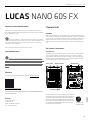 3
3
-
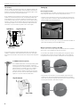 4
4
-
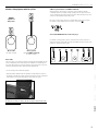 5
5
-
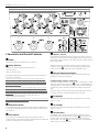 6
6
-
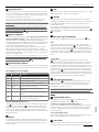 7
7
-
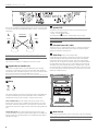 8
8
-
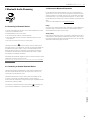 9
9
-
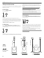 10
10
-
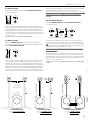 11
11
-
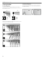 12
12
-
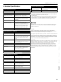 13
13
-
 14
14
-
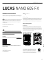 15
15
-
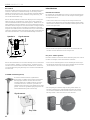 16
16
-
 17
17
-
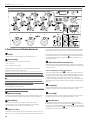 18
18
-
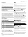 19
19
-
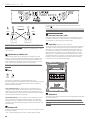 20
20
-
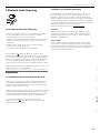 21
21
-
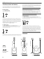 22
22
-
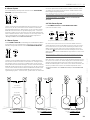 23
23
-
 24
24
-
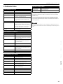 25
25
-
 26
26
-
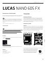 27
27
-
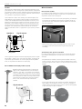 28
28
-
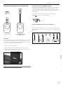 29
29
-
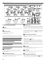 30
30
-
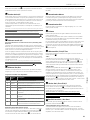 31
31
-
 32
32
-
 33
33
-
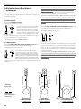 34
34
-
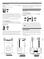 35
35
-
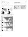 36
36
-
 37
37
-
 38
38
-
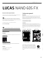 39
39
-
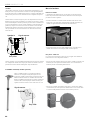 40
40
-
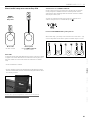 41
41
-
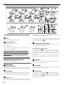 42
42
-
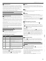 43
43
-
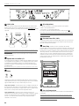 44
44
-
 45
45
-
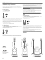 46
46
-
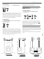 47
47
-
 48
48
-
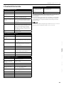 49
49
-
 50
50
-
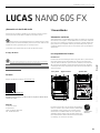 51
51
-
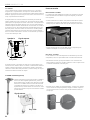 52
52
-
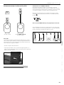 53
53
-
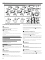 54
54
-
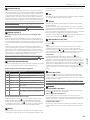 55
55
-
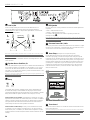 56
56
-
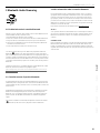 57
57
-
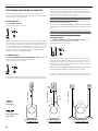 58
58
-
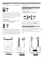 59
59
-
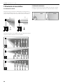 60
60
-
 61
61
-
 62
62
-
 63
63
-
 64
64


HK Audio Lucas Nano 605 FX Manuale utente
- Categoria
- Altoparlanti della soundbar
- Tipo
- Manuale utente
- Questo manuale è adatto anche per
in altre lingue
Documenti correlati
-
HK Audio LUCAS NANO 300 Manuale utente
-
HK Audio LUCAS NANO 608i Stereo System Manuale utente
-
-
-
-
-
HK Audio Lucas Nano 302 Manuale utente
-
-
-