Gigabyte C246M-WU4 Manuale del proprietario
- Tipo
- Manuale del proprietario

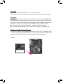
To reduce the impacts on global warming, the packaging materials of this product
are recyclable and reusable. GIGABYTE works with you to protect the environment.
For more product details, please visit GIGABYTE's website.
C246M-WU4
User's Manual
Rev. 1101
12ME-246MWU4-1101R

Copyright
© 2021 GIGA-BYTE TECHNOLOGY CO., LTD. All rights reserved.
The trademarks mentioned in this manual are legally registered to their respective owners.
Disclaimer
Information in this manual is protected by copyright laws and is the property of GIGABYTE.
Changes to the specications and features in this manual may be made by GIGABYTE without
prior notice. No part of this manual may be reproduced, copied, translated, transmitted, or
published in any form or by any means without GIGABYTE's prior written permission.
In order to assist in the use of this product, carefully read the User's Manual.
For product-related information, check on our website at: https://www.gigabyte.com
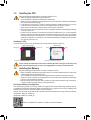
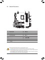
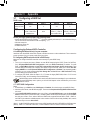
Identifying Your Motherboard Revision
The revision number on your motherboard looks like this: "REV: X.X." For example, "REV:
1.0" means the revision of the motherboard is 1.0. Check your motherboard revision before
updating motherboard BIOS, drivers, or when looking for technical information.
Example:

- 3 -
Table of Contents
C246M-WU4 Motherboard Layout ...................................................................................4
Chapter 1 Hardware Installation .....................................................................................5
1-1 Installation Precautions .................................................................................... 5
1-2 ProductSpecications ...................................................................................... 6
1-3 Installing the CPU ............................................................................................ 9
1-4 Installing the Memory ....................................................................................... 9
1-5 Installing an Expansion Card ......................................................................... 10
1-6 Setting up AMD CrossFire™Conguration ..................................................... 10
1-7 Back Panel Connectors .................................................................................. 11
1-8 Internal Connectors ........................................................................................ 13
Chapter 2 BIOS Setup ..................................................................................................21
2-1 Startup Screen ............................................................................................... 21
2-2 The Main Menu .............................................................................................. 22
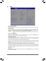
2-3 M.I.T. .............................................................................................................. 23
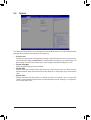
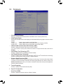
2-4 System ........................................................................................................... 29
2-5 BIOS ............................................................................................................... 30
2-6 Peripherals ..................................................................................................... 33
2-7 Chipset ........................................................................................................... 36
2-8 Power ............................................................................................................. 37
2-9 Save & Exit ..................................................................................................... 39
Chapter 3 Appendix ......................................................................................................40
3-1 ConguringaRAIDSet .................................................................................. 40
3-2 Installing an Intel® Optane™ Memory .............................................................. 42
3-3 Drivers Installation .......................................................................................... 43
RegulatoryNotices .................................................................................................... 44
Contact Us ................................................................................................................ 48

- 4 -
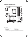
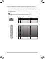
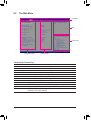
C246M-WU4 Motherboard Layout
* The box contents above are for reference only and the actual items shall depend on the product package you obtain.
The box contents are subject to change without notice.
Box Contents
5C246M-WU4 motherboard 5Four SATA cables
5Motherboard driver disc 5I/O Shield
5User's Manual 5One G Connector
CPU_FAN
ATX
F_AUDIO
DDR4_B2
DDR4_A2
DDR4_B1
DDR4_A1
BAT
F_PANEL
Intel® C246
M_BIOS
F_USB1
LGA1151
F_USB30
PCIEX1_1
iTE®
Super I/O
TPM
M2A
SATA3
7 5 3 1
6 4 2 0
PCIEX8
80 60 42
SYS_FAN2A
SPDIF_O
110
COMB
CODEC
THB_C
SATA_SGP2
SATA_SGP1
SYS_FAN2BCOMA
M2M
80 60 42
CLR_CMOS
KB_MS_USB30 ATX_12V_2X4
AUDIO
PCIEX16 C246M-WU4
USB30_LAN1
DP
SYS_FAN1
USB31_USB30_LAN2
DVI
Intel® GbE
LAN
Intel® GbE
LAN
VGA
PCIEX1_2
F_USB2

Chapter 1 Hardware Installation
1-1 Installation Precautions
The motherboard contains numerous delicate electronic circuits and components which can become
damaged as a result of electrostatic discharge (ESD). Prior to installation, carefully read the user's
manual and follow these procedures:
•Prior to installation, make sure the chassis is suitable for the motherboard.
•Priortoinstallation,donotremoveorbreakmotherboardS/N(SerialNumber)stickeror
warranty sticker provided by your dealer. These stickers are required for warranty validation.
•Always remove the AC power by unplugging the power cord from the power outlet before
installing or removing the motherboard or other hardware components.
•When connecting hardware components to the internal connectors on the motherboard, make
sure they are connected tightly and securely.
•When handling the motherboard, avoid touching any metal leads or connectors.
•It is best to wear an electrostatic discharge (ESD) wrist strap when handling electronic
components such as a motherboard, CPU or memory. If you do not have an ESD wrist strap,
keepyourhandsdryandrsttouchametalobjecttoeliminatestaticelectricity.
•Prior to installing the motherboard, please have it on top of an antistatic pad or within an
electrostatic shielding container.
•Before connecting or unplugging the power supply cable from the motherboard, make sure
the power supply has been turned off.
•Before turning on the power, make sure the power supply voltage has been set according to
the local voltage standard.
•Before using the product, please verify that all cables and power connectors of your hardware
components are connected.
•To prevent damage to the motherboard, do not allow screws to come in contact with the
motherboard circuit or its components.
•Make sure there are no leftover screws or metal components placed on the motherboard or
within the computer casing.
•Do not place the computer system on an uneven surface.
•Do not place the computer system in a high-temperature or wet environment.
•Turning on the computer power during the installation process can lead to damage to system
components as well as physical harm to the user.
•If you are uncertain about any installation steps or have a problem related to the use of the
product,pleaseconsultacertiedcomputertechnician.
•If you use an adapter, extension power cable, or power strip, ensure to consult with its installation
and/or grounding instructions.
- 5 -

1-2 ProductSpecications
CPU LGA1151 package:
- Intel® Xeon® E series processors
-
9th and 8th Generation Intel
®
Core
™
processors/Intel
®
Pentium
®
processors/
Intel
®
Celeron
®
processors
(Go to GIGABYTE's website for the latest CPU support list.)
L3 cache varies with CPU
Chipset Intel® C246 Express Chipset
Memory 4xDDR4DIMMsocketssupportingupto128GBofsystemmemory
Dual channel memory architecture
SupportforDDR42666/2400/2133MHzmemorymodules
SupportforECCUn-bufferedDIMM1Rx8/2Rx8memorymodules
Supportfornon-ECCUn-bufferedDIMM1Rx8/2Rx8/1Rx16memorymodules
SupportforExtremeMemoryProle(XMP)memorymodules
(Go to GIGABYTE's website for the latest supported memory speeds and memory
modules.)
Onboard
Graphics
Integrated Graphics Processor-Intel® UHD Graphics support:
- 1xD-Subport,supportingamaximumresolutionof1920x1200@60Hz
- 1xDVI-Dport,supportingamaximumresolutionof1920x1200@60Hz
* The DVI-D port does not support D-Sub connection by adapter.
- 1xDisplayPort,supportingamaximumresolutionof4096x2304@60Hz
* SupportforDisplayPort1.2version,HDCP2.2,andHDR.
Support for up to 3 displays at the same time
Maximum shared memory of 1 GB
Audio Realtek® Audio CODEC
HighDenitionAudio
2/4/5.1/7.1-channel
Support for S/PDIF Out
LAN 2 x Intel®GbELANchips(10/100/1000Mbit)
Expansion Slots 1 x PCI Express x16 slot, running at x16 (PCIEX16)
* For optimum performance, if only one PCI Express graphics card is to be installed,
be sure to install it in the PCIEX16 slot.
1 x PCI Express x16 slot, running at x8 (PCIEX8)
* The PCIEX8 slot shares bandwidth with the PCIEX16 slot. When the PCIEX8 slot
is populated, the PCIEX16 slot operates at up to x8 mode.
* IfyouinstallagraphicscardinthePCIEX16slotandtheGC-TITANRIDGEcard
in the PCIEX8 slot, make sure to set the PCIE Bifurcation Support item to PCIE
x8/x8 in BIOS Setup.
2 x PCI Express x1 slots
(All of the PCI Express slots conform to PCI Express 3.0 standard.)
Multi-Graphics
Technology
Support for AMD Quad-GPU CrossFire™ and 2-Way AMD CrossFire™
technologies
- 6 -

Storage
Interface
Chipset:
- 1 x M.2 connector (Socket 3, M key, type 2242/2260/2280/22110 PCIe x4/
x2 SSD support) (M2M)
- 1 x M.2 connector (Socket 3, M key, type 2242/2260/2280 SATA and PCIe
x4/x2 SSD support) (M2A)
- 8 x SATA 6Gb/s connectors (SATA3 0~7)
- SupportforRAID0,RAID1,RAID5,andRAID10
* Referto"1-8InternalConnectors,"fortheinstallationnoticesfortheM.2andSATA
connectors.
Intel® Optane™MemoryReady
USB Chipset:
- 1 x USB 3.1 Gen 2 Type-A port (red) on the back panel
- 7 x USB 3.1 Gen 1 ports (5 ports on the back panel, 2 ports available through
the internal USB header)
- 4 x USB 2.0/1.1 ports available through the internal USB headers
Internal
Connectors
1 x 24-pin ATX main power connector
1 x 8-pin ATX 12V power connector
2 x M.2 Socket 3 connectors
8 x SATA 6Gb/s connectors
2 x SATA detection headers
1 x CPU fan header
3 x system fan headers
1 x front panel header
1 x front panel audio header
1 x USB 3.1 Gen 1 header
2 x USB 2.0/1.1 headers
1 x S/PDIF Out header
1 x Thunderbolt™ add-in card connector
1 x Trusted Platform Module (TPM) header (2x6 pin, for the GC-TPM2.0_S
module only)
2 x serial port headers
1 x Clear CMOS jumper
Back Panel
Connectors
1 x PS/2 keyboard/mouse port
1 x D-Sub port
1 x DVI-D port
1 x DisplayPort
1 x USB 3.1 Gen 2 Type-A port (red)
5 x USB 3.1 Gen 1 ports
2xRJ-45ports
6 x audio jacks
I/O Controller iTE® I/O Controller Chip
Hardware
Monitor
Voltage detection
Temperature detection
Fan speed detection
Overheating warning
Fan fail warning
Fan speed control
* Whether the fan speed control function is supported will depend on the fan you install.
- 7 -

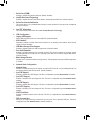
Please visit GIGABYTE's website
for support lists of CPU, memory
modules, SSDs, and M.2 devices.
Please visit the Support\Utility List
page on GIGABYTE's website to
download the latest version of apps.
BIOS 1x128Mbitash
Use of licensed AMI UEFI BIOS
PnP 1.0a, DMI 2.7, WfM 2.0, SM BIOS 2.7, ACPI 5.0
Operating
Properties
Operating temperature: -10°C to 50°C
Operating humidity: 8 - 90%
Non-operatingtemperature:-40°Cto70°C
Non-operatinghumidity:5%-95%
Unique Features Support for APP Center
* Available applications in APP Center may vary by motherboard model. Supported
functionsofeachapplicationmayalsovarydependingonmotherboardspecications.
- @BIOS
- System Information Viewer
Support for Q-Flash
Bundled
Software
Norton® Internet Security (OEM version)
cFosSpeed
Operating
System Support for Windows 10 64-bit
Form Factor Micro ATX Form Factor; 24.4cm x 24.4cm
* GIGABYTE reserves the right to makeany changes to the product specications and product-related information
without prior notice.
- 8 -

DualChannelMemoryConguration
This motherboard provides four memory sockets and supports Dual Channel Technology. After the memory
isinstalled,theBIOSwillautomaticallydetectthespecicationsandcapacityofthememory.EnablingDual
Channel memory mode will double the original memory bandwidth.
The four memory sockets are divided into two channels and each channel has two memory sockets as following:
ChannelA:DDR4_B1,DDR4_B2
ChannelB:DDR4_A1,DDR4_A2
Please visit GIGABYTE's website for details on hardware installation.
1-3 InstallingtheCPU
ReadthefollowingguidelinesbeforeyoubegintoinstalltheCPU:
•Make sure that the motherboard supports the CPU.
(Go to GIGABYTE's website for the latest CPU support list.)
•Always turn off the computer and unplug the power cord from the power outlet before installing the
CPU to prevent hardware damage.
•Locate the pin one of the CPU. The CPU cannot be inserted if oriented incorrectly. (Or you may
locate the notches on both sides of the CPU and alignment keys on the CPU socket.)
•Apply an even and thin layer of thermal grease on the surface of the CPU.
•Do not turn on the computer if the CPU cooler is not installed, otherwise overheating and damage
of the CPU may occur.
•SettheCPUhostfrequencyinaccordancewiththeCPUspecications.Itisnotrecommended
thatthesystembusfrequencybesetbeyondhardwarespecicationssinceitdoesnotmeetthe
standard requirements for the peripherals. If you wish to set the frequency beyond the standard
specications,pleasedosoaccordingtoyourhardwarespecicationsincludingtheCPU,graphics
card, memory, hard drive, etc.
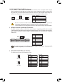
InstallingtheCPU
Locate the alignment keys on the motherboard CPU socket and the notches on the CPU.
DonotremovetheCPUsocketcoverbeforeinsertingtheCPU.Itmaypopofffromtheload
plateautomaticallyduringtheprocessofre-engagingtheleverafteryouinserttheCPU.
1-4 InstallingtheMemory
Readthefollowingguidelinesbeforeyoubegintoinstallthememory:
•Make sure that the motherboard supports the memory. It is recommended that memory of the same
capacity, brand, speed, and chips be used.
(Go to GIGABYTE's website for the latest supported memory speeds and memory modules.)
•Always turn off the computer and unplug the power cord from the power outlet before installing the
memory to prevent hardware damage.
•Memory modules have a foolproof design. A memory module can be installed in only one direction.
If you are unable to insert the memory, switch the direction.
Triangle Pin One Marking on the CPU
NotchNotch
LGA1151 CPU
Alignment KeyAlignment Key
LGA1151 CPU Socket
Pin One Corner of the CPU Socket
- 9 -

1-5 InstallinganExpansionCard
Readthefollowingguidelinesbeforeyoubegintoinstallanexpansioncard:
•Make sure the motherboard supports the expansion card. Carefully read the manual that came
with your expansion card.
•Always turn off the computer and unplug the power cord from the power outlet before installing an
expansion card to prevent hardware damage.
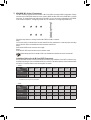
DualChannelMemoryCongurationsTable
DDR4_B1 DDR4_B2 DDR4_A1 DDR4_A2
2 Modules - - DS/SS - - DS/SS
DS/SS - - DS/SS - -
4 Modules DS/SS DS/SS DS/SS DS/SS
(SS=Single-Sided,DS=Double-Sided,"--"=NoMemory)
Due to CPU limitations, read the following guidelines before installing the memory in Dual Channel mode.
1. Dual Channel mode cannot be enabled if only one memory module is installed.
2. When enabling Dual Channel mode with two or four memory modules, it is recommended that memory
of the same capacity, brand, speed, and chips be used.
Procedure and driver screen for enabling CrossFire technology may differ by graphics cards and driver version.
RefertothemanualthatcamewithyourgraphicscardsformoreinformationaboutenablingCrossFiretechnology.
1-6 SettingupAMDCrossFire™Conguration
B.ConnectingtheGraphicsCards
Step 1:
Install CrossFire graphics cards on the PCI Express x16 slots.
Step 2:
Insert the CrossFire (Note) bridge connectors in the CrossFire gold edge connectors on top of the cards.
Step 3:
Plug the display cable into the graphics card on the PCIEX16 slot.
C.ConguringtheGraphicsCardDriver
ToEnableCrossFireFunction
After installing the graphics card driver in the operating system, go to the AMDRADEONSETTINGS screen.
Browse to Gaming\GlobalSettings and ensure AMDCrossFire is set to On.
A.SystemRequirements
-Windows 10 64-bit operating system
-A CrossFire-supported motherboard with two PCI Express x16 slots and correct driver
-CrossFire-ready graphics cards of identical brand and chip and correct driver
-CrossFire (Note) bridge connectors
-Apowersupplywithsufcientpowerisrecommended(Refertothemanualofyourgraphicscardsforthe
power requirement)
(Note) Thebridgeconnector(s)maybeneededornotdependingonyourgraphicscards.
- 10 -

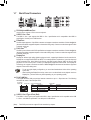
1-7 Back Panel Connectors
PS/2 Keyboard/Mouse Port
Use this port to connect a PS/2 mouse or keyboard.
USB3.1Gen1Port
TheUSB3.1Gen1portsupportstheUSB3.1Gen1specicationandiscompatibletotheUSB2.0
specication.UsethisportforUSBdevices.
D-Sub Port
TheD-Subportsupportsa15-pinD-Subconnectorandsupportsamaximumresolutionof1920x1200@60Hz
(the actual resolutions supported depend on the monitor being used). Connect a monitor that supports D-Sub
connection to this port.
DVI-D Port (Note)
TheDVI-DportconformstotheDVI-Dspecicationandsupportsamaximumresolutionof1920x1200@60Hz
(the actual resolutions supported depend on the monitor being used). Connect a monitor that supports DVI-D
connection to this port.
DisplayPort
DisplayPort delivers high quality digital imaging and audio, supporting bi-directional audio transmission.
DisplayPort can support both DPCP and HDCP 2.2 content protection mechanisms. It provides improved
visualssupporting Rec. 2020 (Wide Color Gamut) andHigh Dynamic Range (HDR) for Blu-ray UHD
playback.YoucanusethisporttoconnectyourDisplayPort-supportedmonitor.Note:TheDisplayPort
Technologycansupportamaximumresolutionof4096x2304@60Hzbuttheactualresolutionssupported
depend on the monitor being used.
• Tosetupatriple-displayconguration,youmustinstallmotherboarddriversintheoperating
systemrst.
• After installing the DisplayPort device, make sure to set the default sound playback device to
DisplayPort. (The item name may differ depending on your operating system.)
RJ-45LANPort
TheGigabitEthernetLANportprovidesInternet connection at up to1Gbpsdatarate.Thefollowing
describesthestatesoftheLANportLEDs.
Activity LED
Connection/
Speed LED
LANPort
Activity LED:Connection/Speed LED:
State Description
Orange 1 Gbps data rate
Green 100 Mbps data rate
Off 10 Mbps data rate
State Description
Blinking Data transmission or receiving is occurring
On Nodatatransmissionorreceivingisoccurring
USB3.1Gen2Type-APort(Red)
TheUSB3.1Gen2Type-AportsupportstheUSB3.1Gen2specicationandiscompatibletotheUSB
3.1Gen1andUSB2.0specication.UsethisportforUSBdevices.
(Note) TheDVI-DportdoesnotsupportD-Subconnectionbyadapter.
- 11 -

•Whenremovingthecableconnectedtoabackpanelconnector,rstremovethecablefromyour
device and then remove it from the motherboard.
•When removing the cable, pull it straight out from the connector. Do not rock it side to side to
prevent an electrical short inside the cable connector.
PleasevisitGIGABYTE'swebsitefordetailsonconguringtheaudiosoftware.
Center/SubwooferSpeakerOut(Orange)
Use this audio jack to connect center/subwoofer speakers.
RearSpeakerOut(Black)
Use this audio jack to connect rear speakers.
SideSpeakerOut(Gray)
Use this audio jack to connect side speakers.
LineIn(Blue)
The line in jack. Use this audio jack for line in devices such as an optical drive, walkman, etc.
LineOut/FrontSpeakerOut(Green)
The line out jack.
MicIn(Pink)
The Mic in jack.
AudioJackCongurations:
Jack Headphone/
2-channel 4-channel 5.1-channel 7.1-channel
Center/Subwoofer Speaker Out a a
RearSpeakerOut aaa
Side Speaker Out a
Line In
Line Out/Front Speaker Out aaaa
Mic In
- 12 -

1-8 Internal Connectors
Readthefollowingguidelinesbeforeconnectingexternaldevices:
•First make sure your devices are compliant with the connectors you wish to connect.
•Before installing the devices, be sure to turn off the devices and your computer. Unplug the power
cord from the power outlet to prevent damage to the devices.
•After installing the device and before turning on the computer, make sure the device cable has
been securely attached to the connector on the motherboard.
2
415
1
43
7
12
6
9
813 17
5
14
7
16
10
11
4
1) ATX_12V_2X4
2) ATX
3) CPU_FAN
4) SYS_FAN1/2A/2B
5) SATA30/1/2/3/4/5/6/7
6) SATA_SGP1/2
7) M2M/M2A
8) F_PANEL
9) F_AUDIO
10) SPDIF_O
11) F_USB30
12) F_USB1/F_USB2
13) THB_C
14) TPM
15) COMA/COMB
16) BAT
17) CLR_CMOS
- 13 -

DEBUG
PORT
G.QBOFM
131
24
12
ATX
1/2)ATX_12V_2X4/ATX(2x4,12VPowerConnectorand2x12MainPowerConnector)
With the use of the power connector, the power supply can supply enough stable power to all the components
onthemotherboard.Beforeconnectingthepowerconnector,rstmakesurethepowersupplyisturned
off and all devices are properly installed. The power connector possesses a foolproof design. Connect the
power supply cable to the power connector in the correct orientation.
The 12V power connector mainly supplies power to the CPU. If the 12V power connector is not connected,
the computer will not start.
To meet expansion requirements, it is recommended that a power supply that can withstand high
power consumption be used (500W or greater). If a power supply is used that does not provide the
required power, the result can lead to an unstable or unbootable system.
ATX:
PinNo. Denition PinNo. Denition
1 3.3V 13 3.3V
2 3.3V 14 -12V
3GND 15 GND
4 +5V 16 PS_ON(softOn/Off)
5GND 17 GND
6 +5V 18 GND
7GND 19 GND
8 Power Good 20 NC
9 5VSB (stand by +5V) 21 +5V
10 +12V 22 +5V
11 +12V (Only for 2x12-pin
ATX)
23 +5V (Only for 2x12-pin ATX)
12 3.3V (Only for 2x12-pin ATX) 24 GND(Onlyfor2x12-pinATX)
ATX_12V_2X4:
PinNo. Denition PinNo. Denition
1GND(Onlyfor2x4-pin12V) 5+12V (Only for 2x4-pin 12V)
2GND(Onlyfor2x4-pin12V) 6+12V (Only for 2x4-pin 12V)
3GND 7 +12V
4GND 8 +12V
DEBUG
PORT
G.QBOFM
ATX_12V_2X4
41
85
- 14 -

3/4)CPU_FAN/SYS_FAN1/2A/2B(FanHeaders)
All fan headers on this motherboard are 4-pin. Most fan headers possess a foolproof insertion design.
When connecting a fan cable, be sure to connect it in the correct orientation (the black connector wire is
the ground wire). The speed control function requires the use of a fan with fan speed control design. For
optimum heat dissipation, it is recommended that a system fan be installed inside the chassis.
•Be sure to connect fan cables to the fan headers to prevent your CPU and system from
overheating. Overheating may result in damage to the CPU or the system may hang.
•Thesefanheadersarenotcongurationjumperblocks.Donotplaceajumpercapontheheaders.
PinNo. Denition
1GND
2 Voltage Speed Control
3 Sense
4 PWM Speed Control
CPU_FAN
DEBUG
PORT
G.QBOFM
1
SYS_FAN2B
DEBUG
PORT
G.QBOFM
1
DEBUG
PORT
G.QBOFM
1
SYS_FAN1/SYS_FAN2A
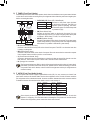
5) SATA30/1/2/3/4/5/6/7(SATA6Gb/sConnectors)
The SATA connectors conform to SATA 6Gb/s standard and are compatible with SATA 3Gb/s and SATA
1.5Gb/s standard. Each SATA connector supports a single SATA device. The Intel®ChipsetsupportsRAID0,
RAID1,RAID5,andRAID10.RefertoChapter3,"ConguringaRAIDSet,"forinstructionsonconguring
aRAIDarray.
PinNo. Denition
1GND
2 TXP
3TXN
4GND
5RXN
6RXP
7GND
Toenablehot-pluggingfortheSATAports,refertoChapter2,"BIOSSetup,""Peripherals\SATA
AndRSTConguration,"formoreinformation.
SATA3
1
1
7
7
DEBUG
PORT
G.QBOFM
7 5 3 1
6 4 2 0
DEBUG
PORT
G.QBOFM
DEBUG
PORT
G.QBOFM
DEBUG
PORT
G.QBOFM
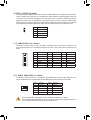
6) SATA_SGP1/2(SATADetectionHeaders)
The headers can connect to SATA detection devices.
PinNo. Denition
1NC
2NoPin
3DATA0
4NC
5NC
6 LOAD
7NC
8 CLOCK
PinNo. Denition
1NC
2NoPin
3DATA1
4NC
5NC
6 LOAD
7NC
8 CLOCK
SATA_SGP1: SATA_SGP2:
F_USB30 F_U
B_
F_ F_
_
B
BS_
B
SB_
B
_S
S_
_
B
_U
_
B
S
123
123
123
123
1
1
1
1
BSS
S
_S
SSU
1 2 3 4 5
S3 BSSS
U
__ 3
F_USB3F
S _
S _
S _
SF
B_
B_
F
_0
S
S
_0F
_F
_
_
__B
U
S _S
_ SF_
B
USB0_B
B_ F_USB3
F_USB303
_
_3U
S_
12
7
8
SATA_SGP1
F_USB30 F_U
B_
F_ F_
_
B
BS_
B
SB_
B
_S
S_
_
B
_U
_
B
S
123
123
123
123
1
1
1
1
BSS
S
_S
SSU
1 2 3 4 5
S3 BSSS
U
__ 3
F_USB3F
S _
S _
S _
SF
B_
B_
F
_0
S
S
_0F
_F
_
_
__B
U
S _S
_ SF_
B
USB0_B
B_ F_USB3
F_USB303
_
_3U
S_
12
7
8
SATA_SGP2
- 15 -

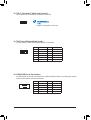
InstallationNoticesfortheM.2andSATAConnectors:
Due to the limited number of lanes provided by the Chipset, the availability of the SATA connectors may
be affected by the type of device installed in the M.2 connector. The M2A connector shares bandwidth with
the SATA3 1 connector.Refertothefollowingtablefordetails.
7) M2A/M2M(M.2Socket3Connectors)
TheM.2connectorsupportsM.2SATASSDsorM.2PCIeSSDsandsupportRAIDconguration.Please
notethatanM.2PCIeSSDcannotbeusedtocreateaRAIDseteitherwithanM.2SATASSDoraSATA
harddrive.TocreateaRAIDarraywithanM.2PCIeSSD,youmustsetupthecongurationinUEFIBIOS
mode.RefertoChapter3,"ConguringaRAIDSet,"forinstructionsonconguringaRAIDarray.
Follow the steps below to correctly install an M.2 SSD in the M.2 connector.
Step 1:
Use a screw driver to unfasten the screw and standoff from the motherboard. Locate the proper mounting
holefortheM.2SSDtobeinstalledandthenscrewthestandoffrst.
Step 2:
Slide the M.2 SSD into the connector at an angle.
Step 3:
Press the M.2 SSD down and then secure it with the screw.
Select the proper hole for the M.2 SSD to be installed and refasten the screw and standoff.
•M2A:
SATA3 0 SATA3 1 SATA3 2 SATA3 3 SATA3 4 SATA3 5 SATA3 6 SATA3 7
M.2 SATA SSD ara a a a a a
M.2 PCIe SSD
aaaaaaaa
NoM.2SSDInstalled aaaaaaaa
a: Available, r:Notavailable
Connector
Type of
M.2 SSD
•M2M:
SATA3 0 SATA3 1 SATA3 2 SATA3 3 SATA3 4 SATA3 5 SATA3 6 SATA3 7
M.2 PCIe SSD *
aaaaaaaa
NoM.2SSDInstalled a a a a a a a a
a: Available, r:Notavailable
* The M2M connector supports only PCIe SSDs.
Connector
Type of
M.2 SSD
F_USB30 F_U
B_
F_ F_
_
B
BS_
B
SB_
B
_S
S_
_
B
_U
_
B
S
123
123
123
123
1
1
1
1
BSS
S
_S
SSU
1 2 3 4 5
S3 BSSS
U
__ 3
F_USB3F
S _
S _
S _
SF
B_
B_
F
_0
S
S
_0F
_F
_
_
__B
U
S _S
_ SF_
B
USB0_B
B_ F_USB3
F_USB303
_
_3U
S_
80110 60
M2M
42
F_USB30 F_U
B_
F_ F_
_
B
BS_
B
SB_
B
_S
S_
_
B
_U
_
B
S
123
123
123
123
1
1
1
1
BSS
S
_S
SSU
1 2 3 4 5
S3 BSSS
U
__ 3
F_USB3F
S _
S _
S _
SF
B_
B_
F
_0
S
S
_0F
_F
_
_
__B
U
S _S
_ SF_
B
USB0_B
B_ F_USB3
F_USB303
_
_3U
S_
80 60
M2A
42
- 16 -

The front panel design may differ by chassis. A front panel module mainly consists of power switch,
reset switch, power LED, hard drive activity LED, speaker and etc. When connecting your chassis
front panel module to this header, make sure the wire assignments and the pin assignments are
matched correctly.
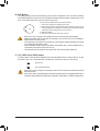
8) F_PANEL(FrontPanelHeader)
Connect the power switch, reset switch, speaker, chassis intrusion switch/sensor and system status indicator
onthechassistothisheaderaccordingtothepinassignmentsbelow.Notethepositiveandnegativepins
before connecting the cables.
System Status LED
S0 On
S3/S4/S5 Off
•PW(PowerSwitch,Red):
Connects to the power switch on the chassis front panel. You may
congurethewaytoturnoffyoursystemusingthepowerswitch(refer
toChapter2,"BIOSSetup,""Power,"formoreinformation).
•SPEAK(Speaker, Orange):
Connects to the speaker on the chassis front panel. The system reports
system startup status by issuing a beep code. One single short beep
will be heard if no problem is detected at system startup.
•PLED/PWR_LED(Power LED, Yellow/Purple):
Connects to the power status indicator
on the chassis front panel. The LED is on
when the system is operating. The LED is
off when the system is in S3/S4 sleep state
or powered off (S5).
•HD (Hard Drive Activity LED, Blue):
Connects to the hard drive activity LED on the chassis front panel. The LED is on when the hard drive
is reading or writing data.
•RES(ResetSwitch,Green):
Connects to the reset switch on the chassis front panel. Press the reset switch to restart the computer
ifthecomputerfreezesandfailstoperformanormalrestart.
•CI (Chassis Intrusion Header, Gray):
Connects to the chassis intrusion switch/sensor on the chassis that can detect if the chassis cover has
been removed. This function requires a chassis with a chassis intrusion switch/sensor.
•NC(Orange): Noconnection.
9) F_AUDIO(FrontPanelAudioHeader)
ThefrontpanelaudioheadersupportsHighDenitionaudio(HD).Youmayconnectyourchassisfront
panel audio module to this header. Make sure the wire assignments of the module connector match the
pin assignments of the motherboard header. Incorrect connection between the module connector and the
motherboard header will make the device unable to work or even damage it.
Some chassis provide a front panel audio module that has separated connectors on each wire
instead of a single plug. For information about connecting the front panel audio module that has
different wire assignments, please contact the chassis manufacturer.
F_USB30 F_U
B_
F_ F_
_
B
BS_
B
SB_
B
_S
S_
_
B
_U
_
B
S
123
123
123
123
1
1
1
1
BSS
S
_S
SSU
1 2 3 4 5
S3 BSSS
U
__ 3
F_USB3F
S _
S _
S _
SF
B_
B_
F
_0
S
S
_0F
_F
_
_
__B
U
S _S
_ SF_
B
USB0_B
B_ F_USB3
F_USB303
_
_3U
S_
9 1
10 2
PinNo. Denition PinNo. Denition
1 MIC2_L 6 Sense
2GND 7FAUDIO_JD
3MIC2_R 8NoPin
4NC 9LINE2_L
5LINE2_R 10 Sense
NC
NC
Power LED
DEBUG
PORT
G.QBOFM
1
2
19
20
CI-
CI+
PWR_LED-
PWR_LED+
PLED-
PW-
SPEAK+
SPEAK-
PLED+
PW+
Power LED
HD-
RES+
HD+
RES-
Hard Drive
Activity LED
Reset
Switch Chassis Intrusion
Header
Power Switch Speaker
PWR_LED-
- 17 -

10) SPDIF_O(S/PDIFOutHeader)
This header supports digital S/PDIF Out and connects a S/PDIF digital audio cable (provided by expansion
cards) for digital audio output from your motherboard to certain expansion cards like graphics cards and
sound cards. For example, some graphics cards may require you to use a S/PDIF digital audio cable for
digital audio output from your motherboard to your graphics card if you wish to connect an HDMI display
to the graphics card and have digital audio output from the HDMI display at the same time. For information
about connecting the S/PDIF digital audio cable, carefully read the manual for your expansion card.
PinNo. Denition
1 5VDUAL
2NoPin
3 SPDIFO
4GND
PinNo. Denition PinNo. Denition PinNo. Denition
1 VBUS 8 D1- 15 SSTX2-
2SSRX1- 9 D1+ 16 GND
3SSRX1+ 10 NC 17 SSRX2+
4GND 11 D2+ 18 SSRX2-
5 SSTX1- 12 D2- 19 VBUS
6 SSTX1+ 13 GND 20 NoPin
7GND 14 SSTX2+
11) F_USB30(USB3.1Gen1Header)
TheheaderconformstoUSB3.1Gen1andUSB2.0specicationandcanprovidetwoUSBports.For
purchasingtheoptional3.5"frontpanelthatprovidestwoUSB3.1Gen1ports,pleasecontactthelocal
dealer.
F_USB30 F_U
B_
F_ F_
_
B
BS_
B
SB_
B
_S
S_
_
B
_U
_
B
S
123
123
123
123
1
1
1
1
BSS
S
_S
SSU
1 2 3 4 5
S3 BSSS
U
__ 3
F_USB3F
S _
S _
S _
SF
B_
B_
F
_0
S
S
_0F
_F
_
_
__B
U
S _S
_ SF_
B
USB0_B
B_ F_USB3
F_USB303
_
_3U
S_
10
20 1
11
F_USB30 F_U
B_
F_ F_
_
B
BS_
B
SB_
B
_S
S_
_
B
_U
_
B
S
123
123
123
123
1
1
1
1
BSS
S
_S
SSU
1 2 3 4 5
S3 BSSS
U
__ 3
F_USB3F
S _
S _
S _
SF
B_
B_
F
_0
S
S
_0F
_F
_
_
__B
U
S _S
_ SF_
B
USB0_B
B_ F_USB3
F_USB303
_
_3U
S_
1
12) F_USB1/F_USB2(USB2.0/1.1Header)
TheheadersconformtoUSB2.0/1.1specication.EachUSBheadercanprovidetwoUSBportsviaan
optional USB bracket. For purchasing the optional USB bracket, please contact the local dealer.
PinNo. Denition PinNo. Denition
1 Power (5V) 6 USB DY+
2 Power (5V) 7 GND
3 USB DX- 8 GND
4 USB DY- 9 NoPin
5 USB DX+ 10 NC
•Do not plug the IEEE 1394 bracket (2x5-pin) cable into the USB 2.0/1.1 header.
•Prior to installing the USB bracket, be sure to turn off your computer and unplug the power cord
from the power outlet to prevent damage to the USB bracket.
DEBUG
PORT
G.QBOFM
10
9
2
1
- 18 -

13) THB_C(Thunderbolt™Add-inCardConnector)
This connector is for a GIGABYTE Thunderbolt™ add-in card.
Supports a Thunderbolt™ add-in card.
14) TPM(TrustedPlatformModuleHeader)
You may connect a TPM (Trusted Platform Module) to this header.
PinNo. Denition PinNo. Denition
1LAD0 7LAD3
2VCC3 8GND
3LAD1 9LFRAME
4NoPin 10 NC
5LAD2 11 SERIRQ
6LCLK 12 LRESET
11 1
F_USB30 F_U
B_
F_ F_
_
B
BS_
B
SB_
B
_S
S_
_
B
_U
_
B
S
123
123
123
123
1
1
1
1
BSS
S
_S
SSU
1 2 3 4 5
S3 BSSS
U
__ 3
F_USB3F
S _
S _
S _
SF
B_
B_
F
_0
S
S
_0F
_F
_
_
__B
U
S _S
_ SF_
B
USB0_B
B_ F_USB3
F_USB303
_
_3U
S_
12 2
F_USB30 F_U
B_
F_ F_
_
B
BS_
B
SB_
B
_S
S_
_
B
_U
_
B
S
123
123
123
123
1
1
1
1
BSS
S
_S
SSU
1 2 3 4 5
S3 BSSS
U
__ 3
F_USB3F
S _
S _
S _
SF
B_
B_
F
_0
S
S
_0F
_F
_
_
__B
U
S _S
_ SF_
B
USB0_B
B_ F_USB3
F_USB303
_
_3U
S_
1
15) COMA/COMB(SerialPortHeaders)
The COM header can provide one serial port via an optional COM port cable. For purchasing the optional
COM port cable, please contact the local dealer.
PinNo. Denition PinNo. Denition
1NDCD- 6NDSR-
2NSIN 7NRTS-
3NSOUT 8NCTS-
4NDTR- 9NRI-
5GND 10 NoPin
10
9
2
1
- 19 -

16) BAT(Battery)
Thebatteryprovidespowertokeepthevalues(suchasBIOScongurations,date,andtimeinformation)
intheCMOSwhenthecomputeristurnedoff.Replacethebatterywhenthebatteryvoltagedropstoalow
level, or the CMOS values may not be accurate or may be lost.
You may clear the CMOS values by removing the battery:
1. Turn off your computer and unplug the power cord.
2. Gently remove the battery from the battery holder and wait for one minute. (Or
use a metal object like a screwdriver to touch the positive and negative terminals
of the battery holder, making them short for 5 seconds.)
3. Replacethebattery.
4. Plug in the power cord and restart your computer.
•Always turn off your computer and unplug the power cord before replacing the battery.
•Replacethebatterywithanequivalentone.Damagetoyourdevicesmayoccurifthebatteryis
replaced with an incorrect model.
•Contact the place of purchase or local dealer if you are not able to replace the battery by yourself
or uncertain about the battery model.
•When installing the battery, note the orientation of the positive side (+) and the negative side (-)
of the battery (the positive side should face up).
•Used batteries must be handled in accordance with local environmental regulations.
17) CLR_CMOS(ClearCMOSJumper)
UsethisjumpertocleartheBIOScongurationandresettheCMOSvaluestofactorydefaults.Toclear
the CMOS values, use a metal object like a screwdriver to touch the two pins for a few seconds.
•Always turn off your computer and unplug the power cord from the power outlet before clearing
the CMOS values.
•Aftersystemrestart,gotoBIOSSetuptoloadfactorydefaults(selectLoadOptimizedDefaults)or
manuallyconguretheBIOSsettings(refertoChapter2,"BIOSSetup,"forBIOScongurations).
Open:Normal
Short: Clear CMOS Values
- 20 -
La pagina sta caricando ...
La pagina sta caricando ...
La pagina sta caricando ...
La pagina sta caricando ...
La pagina sta caricando ...
La pagina sta caricando ...
La pagina sta caricando ...
La pagina sta caricando ...
La pagina sta caricando ...
La pagina sta caricando ...
La pagina sta caricando ...
La pagina sta caricando ...
La pagina sta caricando ...
La pagina sta caricando ...
La pagina sta caricando ...
La pagina sta caricando ...
La pagina sta caricando ...
La pagina sta caricando ...
La pagina sta caricando ...
La pagina sta caricando ...
La pagina sta caricando ...
La pagina sta caricando ...
La pagina sta caricando ...
La pagina sta caricando ...
La pagina sta caricando ...
La pagina sta caricando ...
La pagina sta caricando ...
La pagina sta caricando ...
-
 1
1
-
 2
2
-
 3
3
-
 4
4
-
 5
5
-
 6
6
-
 7
7
-
 8
8
-
 9
9
-
 10
10
-
 11
11
-
 12
12
-
 13
13
-
 14
14
-
 15
15
-
 16
16
-
 17
17
-
 18
18
-
 19
19
-
 20
20
-
 21
21
-
 22
22
-
 23
23
-
 24
24
-
 25
25
-
 26
26
-
 27
27
-
 28
28
-
 29
29
-
 30
30
-
 31
31
-
 32
32
-
 33
33
-
 34
34
-
 35
35
-
 36
36
-
 37
37
-
 38
38
-
 39
39
-
 40
40
-
 41
41
-
 42
42
-
 43
43
-
 44
44
-
 45
45
-
 46
46
-
 47
47
-
 48
48


Gigabyte C246M-WU4 Manuale del proprietario
- Tipo
- Manuale del proprietario
in altre lingue
- English: Gigabyte C246M-WU4 Owner's manual
Documenti correlati
-
Gigabyte Z370N WIFI Manuale utente
-
-
-
-
-
-
-
-
-
Gigabyte X570 AORUS ULTRA Manuale del proprietario