LD Systems AM8 Manuale utente
- Categoria
- Mixer audio
- Tipo
- Manuale utente
Questo manuale è adatto anche per

USER´S MANUAL
BEDIENUNGSANLEITUNG
MANUEL D`UTILISATION
MANUAL DE USUARIO
INSTRUKCJA OBSŁUGI
MANUALE D‘ USO
AM 8
8-CHANNEL AUTOMATIC MIXER
LDAM8

CONTENTS / INHALTSVERZEICHNIS / CONTENU / CONTENIDO / TREŚĆ / CONTENUTO
ENGLISH
PREVENTIVE MEASURES 3-4
INTRODUCTION 4
CONNECTIONS, CONTROLS, AND INDICATORS 5-6
MANUAL OPERATION 7-9
STARTUP 10-11
DAISY-CHAINING 11
ESTABLISHING A CONNECTION WITH A WINDOWS PC 11-13
SOFTWARE MAIN WINDOW 13-15
EQUALIZER CHANNEL 1 - 8 (EDIT EQ) 15-16
EQUALIZER MASTER 1 & 2 17
MASTER LIMITER 1 & 2 18
AUDIO MATRIX 19
SYSTEM SETTINGS 19-20
MENU 21
CHANNEL GROUPS 21
SPECIFICATIONS 22-23
MANUFACTURER´S DECLARATIONS 23
DEUTSCH
SICHERHEITSHINWEISE 24-25
EINFÜHRUNG 25
ANSCHLÜSSE, BEDIEN- UND ANZEIGEELEMENTE 25-27
MANUELLE BEDIENUNG 28-31
INBETRIEBNAHME 31
KASKADIERUNG 32
VERBINDUNG MIT EINEM WINDOWS PC HERSTELLEN 32-34
SOFTWARE HAUPTFENSTER 34-36
EQUALIZER KANAL 1 - 8 (EDIT EQ) 36-38
EQUALIZER MASTER 1 & 2 38
MASTER LIMITER 1 & 2 39
AUDIO MATRIX 40
SYSTEMEINSTELLUNGEN 40-41
MENÜ 42
KANAL-GRUPPEN 42-43
TECHNISCHE DATEN 43-44
HERSTELLERERKLÄRUNGEN 44
FRANCAIS
MESURES PRÉVENTIVES 45-46
INTRODUCTION 46
CONNECTEURS, CONTRÔLES ET INDICATEURS 46-48
UTILISATION MANUELLE 48-52
MISE EN SERVICE 52
CASCADE 53
CONFIGURATION DE LA LIAISON AVEC UN PC
SOUS WINDOWS 53-55
FENÊTRE PRINCIPALE DU LOGICIEL 55-57
ÉGALISEUR CANAUX 1 - 8 (EDIT EQ) 57-58
EQUALIZER MASTER 1 & 2 59
MASTER LIMITER 1 & 2 60
MATRIZ DE AUDIO 61
PARAMÈTRES SYSTÈME 61-62
MENU 63
GROUPES DE CANAUX 63-64
CARACTÉRISTIQUES TECHNIQUES 64-65
DECLARATIONS 65
ESPAÑOL
MEDIDAS DE SEGURIDAD 66-67
INTRODUCCIÓN 67
CONEXIONES, CONTROLES E INDICADORES 67-69
OPERACIÓN MANUAL 70-73
PUESTA EN MARCHA 73-74
CONEXIÓN EN CASCADA 74
CONFIGURATION DE LA LIAISON AVEC UN
PC SOUS WINDOWS 74-76
VENTANA PRINCIPAL DEL PROGRAMA 76-78
ÉGALISEUR CANAUX 1 - 8 (EDIT EQ) 78-79
EQUALIZER MASTER 1 & 2 80
MASTER LIMITER 1 & 2 81
FUNKCJA AUDIO MATRIX 82
CONFIGURACIÓN DEL SISTEMA 82-83
MENÚ 84
GRUPOS DE CANALES 84-85
CARACTERÍSTICAS TÉCNICAS 85-86
DECLARACIÓN DEL FABRICANTE 86
POLSKI
ŚRODKI OSTROŻNOŚCI 87-88
WPROWADZENIE 88
PRZYŁĄCZA, ELEMENTY OBSŁUGI I WSKAŹNIKI 88-90
OBSŁUGA RĘCZNA 91-94
URUCHOMIENIE 94
KASKADOWANIE 95
NAWIĄZYWANIE POŁĄCZENIA Z KOMPUTEREM Z
SYSTEMEM OPERACYJNYM WINDOWS 96-97
GŁÓWNE OKNO PROGRAMU 98-100
EDIT EQ (ZMIANA USTAWIEŃ KOREKTORA
DŹWIĘKU DLA KANAŁÓW 1–8) 100-101
EQUALIZER MASTER 1 & 2 101-102
MASTER LIMITER 1 & 2 102-103
FUNKCJA AUDIO MATRIX 103
USTAWIENIA SYSTEMU 103-105
MENÜ 105
GRUPY KANAŁÓW 106-108
DEKLARACJE PRODUCENTA 108
ITALIANO
MISURE PRECAUZIONALI 109-110
INTRODUZIONE 110
CONNESSIONI, COMANDI E INDICATORI 110-112
FUNZIONAMENTO MANUALE 113-116
MESSA IN FUNZIONE 116-117
COLLEGAMENTO A CASCATA 117
COLLEGAMENTO A UN PC CON SISTEMA
OPERATIVO WINDOWS 117-119
FINESTRA PRINCIPALE DEL SOFTWARE 119-121
EQUALIZZATORE CANALE 1 - 8 (MODIFICA EQUALIZZATORE) 121-122
EQUALIZER MASTER 1 & 2 123
MASTER LIMITER 1 & 2 124
MATRICE AUDIO 125
IMPOSTAZIONI DI SISTEMA 125-126
MENU 127
GRUPPI DI CANALI 127-128
DATI TECNICI 128
DICHIARAZIONI DEL PRODUTTORE 128-129

ITALIANOPOLSKIESPAÑOL
FRANCAISDEUTSCHENGLISH
3
ENGLISH
YOU‘VE MADE THE RIGHT CHOICE!
We have designed this product to operate reliably over many years. LD Systems stands for this with its name and many years of experience
as a manufacturer of high-quality audio products. Please read this User‘s Manual carefully, so that you can begin making optimum use of
your LD Systems product quickly.
You can find more information about LD-SYSTEMS at our Internet site WWW.LD-SYSTEMS.COM
PREVENTIVE MEASURES
1. Please read these instructions carefully.
2. Keep all information and instructions in a safe place.
3. Follow the instructions.
4. Observe all safety warnings. Never remove safety warnings or other information from the equipment.
5. Use the equipment only in the intended manner and for the intended purpose.
6. Use only sufficiently stable and compatible stands and/or mounts (for fixed installations). Make certain that wall mounts are properly
installed and secured. Make certain that the equipment is installed securely and cannot fall down.
7. During installation, observ e the applicable safety regulations for your country.
8. Never install and operate the equipment near radiators, heat registers, ovens or other sources of heat. Make certain that the equipment is
always installed so that is cooled sufficiently and cannot overheat.
9. Never place sources of ignition, e.g., burning candles, on the equipment.
10. Ventilation slits must not be blocked.
11. Do not use this equipment in the immediate vicinity of water (does not apply to special outdoor equipment - in this case, observe the
special instructions noted below. Do not expose this equipment to flammable materials, fluids or gases. Avoid direct sunlight!
12. Make certain that dripping or splashed water cannot enter the equipment. Do not place containers filled with liquids, such as vases or
drinking vessels, on the equipment.
13. Make certain that objects cannot fall into the device.
14. Use this equipment only with the accessories recommended and intended by the manufacturer.
15. Do not open or modify this equipment.
16. After connecting the equipment, check all cables in order to prevent damage or accidents, e.g., due to tripping hazards.
17. During transport, make certain that the equipment cannot fall down and possibly cause property damage and personal injuries.
18. If your equipment is no longer functioning properly, if fluids or objects have gotten inside the equipment or if it has been damaged in
anot her way, switch it off immediately and unplug it from the mains outlet (if it is a powered device). This equipment may only be repaired
by authorized, qualified personnel.
19. Clean the equipment using a dry cloth.
20. Comply with all applicable disposal laws in your country. During disposal of packaging, please separate plastic and paper/cardboard.
21. Plastic bags must be kept out of reach of children.
FOR EQUIPMENT THAT CONNECTS TO THE POWER MAINS
22. CAUTION: If the power cord of the device is equipped with an earthing contact, then it must be connected to an outlet with a protective
ground. Never deactivate the protective ground of a power cord.
23. If the equipment has been exposed to strong fluctuations in temperature (for example, after transport), do not switch it on immediately.
Moisture and condensation could damage the equipment. Do not switch on the equipment until it has reached room temperature.
24. Before connecting the equipment to the power outlet, first verify that the mains voltage and frequency match the values specified on the
equipment. If the equipment has a voltage selection switch, connect the equipment to the power outlet only if the equipment values and the
mains power values match. If the included power cord or power adapter does not fit in your wall outlet, contact your electrician.
25. Do not step on the power cord. Make certain that the power cable does not become kinked, especially at the mains outlet and/or power
adapter and the equipment connector.
26. When connecting the equipment, make certain that the power cord or power adapter is always freely accessible. Always disconnect the
equipment from the power supply if the equipment is not in use or if you want to clean the equipment. Always unplug the power cord and
power adapter from the power outlet at the plug or adapter and not by pulling on the cord. Never touch the power cord and power adapter
with wet hands.
27. Whenever possible, avoid switching the equipment on and off in quick succession because otherwise this can shorten the useful life of
the equipment.
28. IMPORTANT INFORMATION: Replace fuses only with fuses of the same type and rating. If a fuse blows repeatedly, please contact an
authorised service centre.
29. To disconnect the equipment from the power mains completely, unplug the power cord or power adapter from the power outlet.
30. If your device is equipped with a Volex power connector, the mating Volex equipment connector must be unlocked before it can be removed.
However, this also means that the equipment can slide and fall down if the power cable is pulled, which can lead to personal injuries and/or
other damage. For this reason, always be careful when laying cables.
31. Unplug the power cord and power adapter from the power outlet if there is a risk of a lightning strike or before extended periods of disuse.

4
DEUTSCHFRANCAIS
ESPAÑOL
ENGLISH
ITALIANO POLSKI
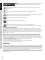
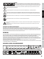
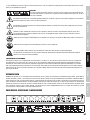
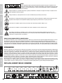
CAUTION:
To reduce the risk of electric shock, do not remove cover (or back). There are no user serviceable parts
inside. Maintenance and repairs should be exclusively carried out by qualified service personnel.
The warning triangle with lightning symbol indicates dangerous uninsulated voltage inside the unit, which may cause an
electrical shock.
The warning triangle with exclamation mark indicates important operating and maintenance instructions.
Warning! This symbol indicates a hot surface. Certain parts of the housing can become hot during operation. After use, wait for
a cool-down period of at least 10 minutes before handling or transporting the device.
Warning! This device is designed for use below 2000 metres in altitude.
Warning! This product is not intended for use in tropical climates.
To prevent possible hearing damage, avoid listening at high volume levels over long periods of time.
Even exposure to short bursts of loud noise can result in hearing loss. Please keep the volume constantly at a comfortable level.
CAUTION! HIGH VOLUMES IN AUDIO PRODUCTS!
This device is meant for professional use. Therefore, commercial use of this equipment is subject to the respectively applicable national
accident prevention rules and regulations. As a manufacturer, Adam Hall is obligated to notify you formally about the existence of potential
health risks.
Hearing damage due to high volume and prolonged exposure: When in use, this product is capable of producing high sound-pressure levels
(SPL) that can lead to irreversible hearing damage in performers, employees, and audience members. For this reason, avoid prolonged
exposure to volumes in excess of 90 dB.
NOTE: This equipment has been tested and found to comply with the limits for a Class B digital device, pursuant to Part 15 of the FCC
Rules. These limits are designed to provide reasonable protection against harmful interference in a residential installation. This equipment
generates, uses and can radiate radio frequency energy and, if not installed and used in accordance with the instructions, may cause
harmful interference to radio communications. However, there is no guarantee that interference will not occur in a particular installation. If
this equipment does cause harmful interference to radio or television reception, which can be determined by turning the equipment off and
on, the user is encouraged to try to correct the interference by one or more of the following measures:
- Reorient or relocate the receiving antenna.
- Increase the separation between the equipment and receiver.
- Connect the equipment into an outlet on a circuit different from that to which the receiver is connected.
- Consult the dealer or an experienced radio/TV technician for help.
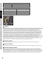
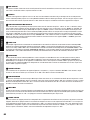
INTRODUCTION
The LD Systems AM 8 is an automatic 8 x 2 matrix mixer with balanced mic line inputs, 96 kHz/24 bit signal processing and a frequency
response of 20 Hz - 30 kHz. The Priority function of the AM8 automatic mixer can be switched on individually for each input; the total threshold
for channel activation is selected automatically or manually using the threshold controller. When the levels of input channels drop below a
certain threshold, these will be muted by the Automix feature. This means that for the transmission of a channel, background noise, feedback
and unwanted comb-filter effects from other active channels are effectively suppressed and the speech intelligibility is thus enhanced. When
the levels of input channels rise above a certain threshold, these will be automatically activated.
On the front panel, encoders with LED ring and peak value display for gain control in 1 dB increments, are used for selecting the input
sensitivity and priority. A Master encoder with two LED chains is used to adjust the output level, turning on output 1, 2, or both and to select
microphone or line level.

ITALIANOPOLSKIESPAÑOL
FRANCAISDEUTSCHENGLISH
5
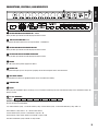
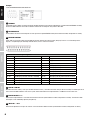
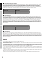
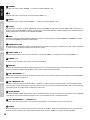
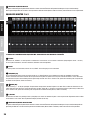
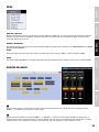
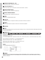
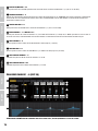
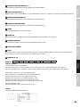
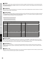
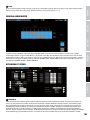
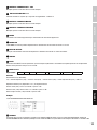
CONNECTIONS, CONTROLS, AND INDICATORS
110-240 AC / 50-60Hz
MAX 60 W / AC~
RS-232
RESET
NETWORK AES/EBU OUTPUT
+ I - I G + I - I G + I - I G + I - I G + I - I G + I - I G + I - I G + I - I G + I - I G + I - I G
LINK IN LINK OUT MASTER
OUTPUT 2
MASTER
OUTPUT 1
EXTERNAL CONTROL
CH 8 CH 7 CH 6 CH 5 CH 4 CH 3 CH 2 CH 1
LD SYSTEMS
®
is a registered Brand of
Adam Hall Germany
· Daimlerstr. 9
61267 Neu-Anspach
+ I - I G
CAUTION! DO NOT OPEN RISK OF ELECTRICAL SHOCK !
AVIS! NE PAS OUVRIR RISQUE DE CHOC ELECTRIQUE !
ACHTUNG! NICHT ÖFFNEN, STROMSCHLAGGEFAHR !
4 51 3
2 6
7 8
10
11 12 14
13
15 16
9
1
SETTING AND DISPLAY ELEMENT CH 1 - CH 8
Rotary encoder, push-button and LED display with multi-function.
2
LED DISPLAYS MASTER 1 & 2
6-segment LED level meter for the sum signals Master 1 and Master 2.
3
SETTING AND DISPLAY ELEMENT MASTER
Rotary encoder, push-button and LED display with multi-function.
4
SETTING AND DISPLAY ELEMENT THRESHOLD
Rotary encoder, push-button and LED display with multi-function.
5
POWER
On / Off switch for the power supply of the device.
6
POWER-LED
The power LED lights up once the system is properly connected to the power mains and switched on.
7
IEC POWER SOCKET
Used to power the device. An appropriate power cord is included in the delivery.
8
HOUSING FAN
9
RESET
When you press the RESET switch, all settings, such as equalizer and routing, are reset to the default settings. Press and hold the switch for
about 6 seconds.
10
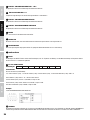
RS-232 INTERFACE
Settings:
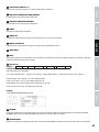
RS-232 Baud: 115200 Data: 8 Stop: 1 Parity: None
Command settings:
RS-232 commands (16 HEX ASCII):
%V, +device address (1 bit), +8 channels volume (8 bit), +master volume (2 bit), +manual threshold level (1 bit), +CRC +#
device address (1 bit): device 1-16, 1 for the master device
channel volume (8 bit): channel 1-8, 0-60 dB, in steps of 1 dB
master volume (2 bit): master volume 1/2, 0-60 dB, in steps of 1dB.
manual threshold level (1 bit): 0-60 dB, in steps of 4 dB.

6
DEUTSCHFRANCAIS
ESPAÑOL
ENGLISH
ITALIANO POLSKI
Example:
%V,01,2020202020202020,3030,0A,AF79#
11
NETWORK
The RS485 interface allows the remote control of the AM8 automatic mixer through a Windows PC (control software AUTOMIX8 included).
Connect the AM8 automatic mixer with the Ethernet interface of the computer using a CAT-5 LAN cable.
12
AES/EBU OUTPUT
Terminal block connector for the output of the sum signal in the digital AES/EBU format (terminal block included, configuration as shown).
13
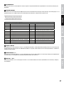
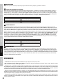
EXTERNAL CONTROL
The D-SUB 25-pin interface offers the possibility of external control of the input channels (CH input). There is a 3.3 V DC voltage at the
outputs 1 to 8 (CH output) for controlling external devices, once a channel is activated.
25-Pin D-SUB connector pin assignment
Pin 1: Ground Pin 14: Ground
Pin 2: Ground Pin 15: Empty
Pin 3: Ground Pin 16: Empty
Pin 4: Ground Pin 17: Empty
Pin 5: Empty Pin 18: CH1 Input (short-to-ground activates channel)
Pin 6: CH1 Output (3,3V when channel is activated) Pin 19: CH2 Input (short-to-ground activates channel)
Pin 7: CH2 Output (3,3V when channel is activated) Pin 20: CH3 Input (short-to-ground activates channel)
Pin 8: CH3 Output (3,3V when channel is activated) Pin 21: CH4 Input (short-to-ground activates channel)
Pin 9: CH4 Output (3,3V when channel is activated) Pin 22: CH5 Input (short-to-ground activates channel)
Pin 10: CH5 Output (3,3V when channel is activated) Pin 23: CH6 Input (short-to-ground activates channel)
Pin 11: CH6 Output (3,3V when channel is activated) Pin 24: CH7 Input (short-to-ground activates channel)
Pin 12: CH7 Output (3,3V when channel is activated) Pin 25: CH8 Input (short-to-ground activates channel)
Pin 13: CH8 Output (3,3V when channel is activated)
14
LINK IN / LINK OUT
Mini DIN connectors to daisy-chain up to 16 AM8 automatic mixers (1 mini DIN connection cable per device included). The audio inputs of all
slave units of the AM8 automatic mixer in the system, will be routed to the line outputs Master 1 and Master 2 of the master unit.
15
MASTER OUTPUT 1 + 2
Balanced line outputs Master 1 and 2 with terminal block connector (terminal block included, configuration as shown). The volume of both
line outputs can be individually adjusted (see point 23).
16
INPUT CH 1 - CH 8
Balanced microphone or line inputs of channels 1 to 8 with terminal block connector (terminal block included, configuration as shown).

ITALIANOPOLSKIESPAÑOL
FRANCAISDEUTSCHENGLISH
7
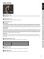
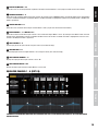
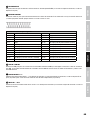
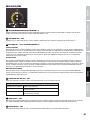
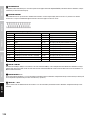
MANUAL OPERATION
18
17
19
21
20 22
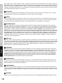
17
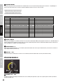
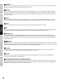
INPUT GAIN CH 1 - CH 8
Rotary encoder for setting the input gain. Turning it to the right increases and turning it to the left reduces the input gain (please observe
LED indicator N°18)
18
LED DISPLAY CH 1 - CH 8
15-segment LED display for the visualisation of the gain input setting.
19
PUSH-BUTTON CH 1 - CH 8
Input sensitivity
To switch an input from microphone to line sensitivity, and vice versa, press and hold the push-button on the rotary encoder of the corresponding
channel for approximately 2 seconds and, if required, turn the rotary encoder until the status LED above LINE flashes red. Then briefly press the
push-button to switch the input sensitivity (see table “LINE / MIC STATUS LED”). If the push-button is not pressed within 5 seconds, there will be no
change and the LED will stop flashing. During the switching process the corresponding channel will be muted and the 15-segment status LED no.
18 will start to flash.
Channel priority
To activate or deactivate the priority of a channel, first press and hold the push-button of the rotary encoder for approximately 2 seconds,
then turn the rotary encoder until the status LED ACTIVE flashes red and then press the push-button on the rotary encoder again. The status
LED ACTIVE lights up continuously when priority is activated and turns off when priority is deactivated. If the push-button is not pressed
within 5 seconds, there will be no change and the LED will stop flashing. During the switching process the corresponding channel will be
muted and the 15-segment status LED no. 18 will start to flash.
Channel mute
Mute the desired channel by briefly pressing on the corresponding push-button. To deactivate the mute, briefly press the appropriate
push-button again. If the mute is active, the 15-segment status LED no. 18 will flash. Setting of the input pre-amplification is also possible
during muting.
20
STATUS-LED LINE / MIC CH 1 - CH 8
The status LED indicates the input sensitivity of each channel CH 1 to CH 8 (see point 19).
STATUS LED LINE / MIC
LED flashing red: ready to switch
LED green Line sensitivity, 48 V phantom power disabled
LED off Microphone sensitivity, 48 V phantom power activated
21
PEAK-LED CH 1 - CH 8
The ACTIVE LED indicates which of the 8 channels of the automatic mixer is currently active.
22
ACTIVE-LED CH 1 - CH 8
The ACTIVE LED indicates which of the 8 channels of the automatic mixer is currently active.

8
DEUTSCHFRANCAIS
ESPAÑOL
ENGLISH
ITALIANO POLSKI
24
23
25
27
2826
23
SUM VOLUME MASTER 1 + 2
Encoder for setting the total volume of the line outputs Master 1 and Master 2 (dual function). If the display LED 1 lights up green (N°26), the
sum volume of the line output Master 1 can be adjusted as desired using the MASTER rotary encoder. If the display LED 2 lights up green
(N°27), the same applies to the line output Master 2. Turning it to the right increases the volume and turning it to the left reduces it.
Select the line output Master 1 or Master 2 for volume setting by first pressing the push-button of the MASTER rotary encoder and then holding
it down for approximately 2 seconds. Now, while the LED display of the currently selected line output from Master 1 (N°26) or Master 2 (N°27)
flashes red, select the other line output for adjusting the total volume using the MASTER rotary encoder. Confirm the selection by pressing
the push-button on the MASTER rotary encoder. By combining the two output channels Master 1 and 2 in a channel group (see CHANNEL
GROUPS), the volume of both channels can be set simultaneously using the MASTER rotary encoder.
24
LED DISPLAY MASTER
15-segment LED display for viewing the volume setting for the line outputs Master 1 or Master 2.
25
PUSH-BUTTON MASTER
Push-button to select the volume or the output level (Line / Mic) of the line outputs Master 1 and 2 (see point 23 and 28).
26
STATUS-LED MASTER 1
If the LED 1 display lights up green, the sum volume of the line output Master 1 can be adjusted as desired using the MASTER rotary
encoder (see also point 23).
27
STATUS-LED MASTER 2
If the LED 2 display lights up green, the sum volume of the line output Master 2 can be adjusted as desired using the MASTER rotary
encoder (see also point 23).

ITALIANOPOLSKIESPAÑOL
FRANCAISDEUTSCHENGLISH
9
28
STATUS-LED LINE
Displays the level status of the Master 1 and Master 2 line outputs. If the green status LED lights up, the output signal of the corresponding
line output Master 1 or Master 2 is output at line level (e.g. for the line input of a power amplifier). If the green status LED does not light up,
the output signal of the corresponding line output Master 1 or Master 2 is output with a 20 dB attenuation (e.g. for the microphone input of a
mixer). First select the line output for which the output level should be changed by pressing the MASTER rotary encoder and holding it down
for approximately 2 seconds, then select the line output (Master 1 or Master 2) with the rotary encoder (status LED flashes red) and confirm
your selection by pushing the push-button. Press and hold the press button of the MASTER rotary encoder for approximately 2 seconds and
turn the rotary encoder until the status LED LINE flashes red.
Now if you press the push-button of the MASTER rotary encoder again, the output is switched to the output level of either line or the
reduced level and vice versa. If the push-button is not pressed within 10 seconds, there will be no change and the LED stops flashing.
STATUS LED MASTER 1 & 2
LED flashing red: ready to switch
LED MASTER 1 green Volume setting Master 1
LED MASTER 2 green Volume setting Master 2
STATUS LED LINE
LED flashing red: ready to switch
LED MASTER 1 green & LINE LED green Master 1 Line level
LED MASTER 2 green & LINE LED green Master 2 Line level
LED MASTER 1 green & LINE LED off Master 1 volume attenuation by 20 dB
LED MASTER 2 green & LINE LED off Master 2 volume attenuation by 20 dB
30
29
31
33
32
34
29
THRESHOLD
Input channels that have a signal level under a certain threshold level can be muted with this function. This means that the transmission
of a channel’s background noise, feedback or unwanted comb filter effects from other active channels are effectively suppressed and
intelligibility of speech is improved. Input channels that have a signal level over a certain threshold value are automatically activated. The
rotary encoder is deactivated for setting the threshold value during automatic operation (status LED no. 32 = green). The threshold value
is automatically adjusted to the volume of the surrounding sounds. The threshold value can also be set manually and individually for each
of the 8 channels. Set the threshold value in order that background noise does not automatically activate an input channel, but that the
activation of a channel speaker etc. is possible. Switch the THRESHOLD function to manual (see point 32 STATUS LED THRESHOLD AUTO
/ MANUAL) and briefly press the push-button of the desired channel (channel mute, 15-segment status LED flashes). Press and hold the
push-button until one of the status LEDs (“LINE” or “ACTIVE”) under the operating element of the corresponding channels flashes red, then
with the help of the THRESHOLD rotary encoder, set the threshold value between 0dB and -60dB as desired (please note the 15-segment
status LED THRESHOLD no. 30, all LED segments off = 0dB, all LED segments on = -60dB). Then briefly press the push-button of the
corresponding channel in order to confirm the setting and deactivate the muting. If there is no input for approximately 10 seconds, the
muting will be automatically deactivated and the currently set value remains the same.
30
LED DISPLAY THRESHOLD
15-segment LED display for viewing the threshold setting in both automatic and manual operation.
31
PUSH-BUTTON THRESHOLD
Push-button to select automatic or manual setting of the threshold value and master or slave operation.

10
DEUTSCHFRANCAIS
ESPAÑOL
ENGLISH
ITALIANO POLSKI
32
STATUS-LED THRESHOLD AUTO / MANUAL
The status LED shows the operating mode of the threshold value setting (green = automatic setting of the threshold value, red = manual
setting of the threshold value, see also point 29). To change the operating mode, press and hold the push-button on the THRESHOLD
rotary encoder for approximately 2 seconds (one of the 3 LEDs AUTO / MANUAL, MASTER or LOCK will now flash red. If necessary, turn
the THRESHOLD rotary encoder until the status LED AUTO / MANUAL flashes red and now press the push-button of the THRESHOLD rotary
encoder again. If the push-button is not pressed within 10 seconds, there will be no change and the LED stops flashing.
STATUS LED THRESHOLD AUTO / MANUAL
LED flashing red: ready to switch
LED AUTO / MANUAL green automatic setting of the threshold value
LED AUTO / MANUAL red manual adjustment of the threshold value
33
STATUS-LED MASTER
When using a single AM8 automatic mixer, it must be configured as a master unit. When daisy-chaining up to 16 AM8 automatic mixers
using the LINK IN / LINK OUT interface on the rear panel of the device (see point 14), the device that must serve as the master unit needs
to be configured as the master unit. If the status LED MASTER is permanently green, then the AM8 automatic mixer is configured as the
master device, and if the LED is not lit, as a slave device. The audio inputs of all slave units of the AM8 automatic mixer in the system are
daisy chained to the line output master 1 and master 2 of the master unit (see DAISY-CHAINING). To change the operating mode press
and hold the push-button of the THRESHOLD rotary encoder for approximately 2 seconds (one of the 3 LEDs AUTO / MANUAL, MASTER or
LOCK will now flash red). If necessary, turn the THRESHOLD rotary encoder until the status LED MASTER flashes red and now press the
push-button of the THRESHOLD rotary encoder again. If the push-button is not pressed within 10 seconds, there will be no change and the
LED stops flashing.
STATUS LED MASTER
LED flashing red: ready to switch
LED MASTER green The device is a master unit
LED MASTER off The device is a slave unit
34
STATUS-LED LOCK
To protect the device from accidental or unauthorised operation there are 3 lock modes available to block the operating elements of the
AM8 automatic mixer (the “POWER” operating element cannot be blocked). These 3 lock modes can only be selected via the management
software (see “PANEL LOCK” point in “SYSTEM SETTINGS”). Activate the selected lock mode by pressing the push-buttons of the operating
elements for channels CH 1 and CH 8 simultaneously for approximately 5 seconds. To deactivate the lock, press and hold the push-button
for CH 1 and CH 8 again for approximately 5 seconds. The status LED “LOCK” lights up green if the lock function is activated and is off if the
lock function is deactivated.
STARTUP
- Use only balanced cables for the connections of the AM8 automatic mixer.
- To avoid damage to the audio system caused by feedback etc., set the volume of the audio system to minimum during the change of settings
and gently increase the volume.
- Since the AM8 automatic mixer is a 19” device with one height unit, the features, settings and displays that are available or visible directly
on the device are limited. Therefore, it is advisable to adjust all settings via the free AUTOMIX8 PC software. Also, visual checking of the input
and output channels and their settings is very comfortable and clearly arranged in the AUTOMIX8 software.
- In the standard setting of the AM8 automatic mixer, all audio inputs are set to microphone sensitivity, also, the 48 V phantom power is
enabled (individual activation / deactivation of the phantom power via the PC software is possible). Do not switch on the equipment until all
microphones are connected.
- Using the same type of microphone for all speakers makes it easier to adjust the settings and improves clarity. If different types of micro-
phones are used, be sure to adjust the input gain and equalizer settings accordingly.
- Make sure that all connected microphones are set to the same level, so as to ensure proper operation of the AM8 automatic mixer.

ITALIANOPOLSKIESPAÑOL
FRANCAISDEUTSCHENGLISH
11
MASTER
SLAVE 1
SLAVE 2
SLAVE 15
110-240 AC / 50-60Hz
MAX 60 W / AC~
RS-232
RESET
NETWORK AES/EBU OUTPUT
+ I - I G + I - I G + I - I G + I - I G + I - I G + I - I G + I - I G + I - I G + I - I G + I - I G
LINK IN LINK OUT MASTER
OUTPUT 2
MASTER
OUTPUT 1
EXTERNAL CONTROL
CH 8 CH 7 CH 6 CH 5 CH 4 CH 3 CH 2 CH 1
LD SYSTEMS
®
is a registered Brand of
Adam Hall Germany
· Daimlerstr. 9
61267 Neu-Anspach
+ I - I G
CAUTION! DO NOT OPEN RISK OF ELECTRICAL SHOCK !
AVIS! NE PAS OUVRIR RISQUE DE CHOC ELECTRIQUE !
ACHTUNG! NICHT ÖFFNEN, STROMSCHLAGGEFAHR !
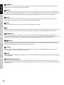
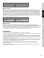
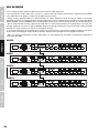
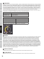
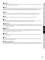
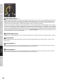
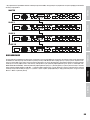
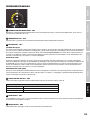
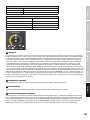
DAISY-CHAINING
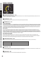
Up to 16 LD Systems AM8 automatic mixers can be daisy-chained to an audio system. When daisy-chaining the AM8 automatic mixers using
the LINK IN / LINK OUT interface on the rear panel of the unit, the device that must serve as the master unit needs to be configured as the
master unit. All other AM8 automatic mixers in the audio system will be configured as slave units (see point 33, CONNECTIONS, CONTROL AND
DISPLAY ELEMENTS). Connect the slave units to the master units unit using the supplied connection cable (slave unit LINK OUT -> Master unit
LINK IN, see figure). The audio inputs of all slave units of the AM8 automatic mixer in the system will be routed to the line outputs Master 1
and Master 2 of the master unit.
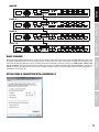
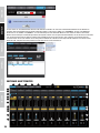
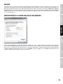
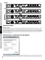
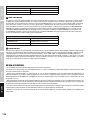
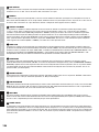
ESTABLISHING A CONNECTION WITH A WINDOWS PC

12
DEUTSCHFRANCAIS
ESPAÑOL
ENGLISH
ITALIANO POLSKI
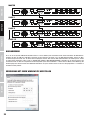
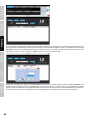
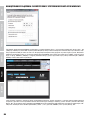
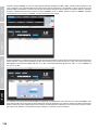
Install the AUTOMIX8 software on a Windows PC (Windows Vista, WIN 7, WIN 8, screen resolution min. 1366 X 768) and connect the AM8 automatic
mixer to the Ethernet interface of the computer using a LAN cable (CAT-5). Since the IP address of the AM8 automatic mixer is factory set to
192.168.1.88, the interface of the computer must be assigned a different IP address (see figure “Properties of Internet Protocol Version 4”). Start
the AUTOMIX8 software, then click with the left mouse button on “MENU”, now move the mouse pointer to “CONNECT” and confirm by clicking
with the left mouse button. Click the blue “SEARCH” field in the opening window.
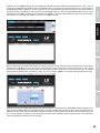
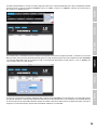
If all settings and connections are properly made, the connected device is displayed after a few seconds with its IP address and an INFO
window announcing “Search finished” (search completed) appears. Press “OK”. To enter the user name (USER NAME) and password (USER
PSW), now click on the blue “OK” field. The factory preset password for the user “admin” and “user” is “000000” (six times the number zero).
Press “OK”.
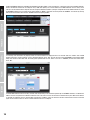
If several AM8 automatic mixers are daisy-chained, and should settings and control be operated by the AUTOMIX8 software, an individual IP
address must be assigned to each individual automatic mixer. The mixers must be connected to the software one by one. While the IP address
is changed, the automatic mixer is restarted. After changing the IP address, you must restart the software and the device must be connected
again. Use an Ethernet switch to connect several automatic mixers to a computer.

ITALIANOPOLSKIESPAÑOL
FRANCAISDEUTSCHENGLISH
13
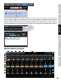
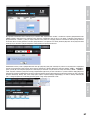
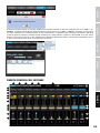
Only one automatic mixer can be connected to the software at any time. To connect a different automatic mixer with the software, remove the
connection of the currently connected mixer by clicking on “MENU” and “DISCONNECT” (see figure). Now click on “MENU” and “CONNECT” to
establish a connection with an automatic mixer with a different IP address. If all settings and connections are properly made, the connected
devices are displayed after a few seconds with their respective IP address and an INFO window announcing “Search finished” (search completed)
appears. Press “OK”. Now select the desired device by clicking on the corresponding IP address, click on the blue “OK” field and type your user
name and password as usual.
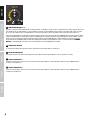
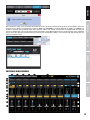
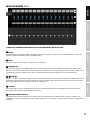
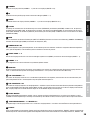
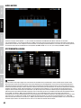
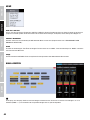
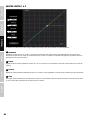
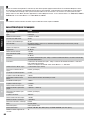
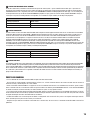
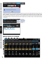
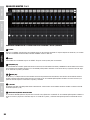
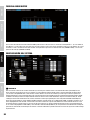
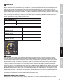
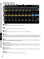
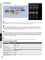
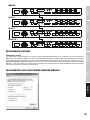
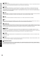
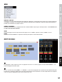
SOFTWARE MAIN WINDOW
1 2 3 4 5 6
9 9
11
10
12
13
14
16
18
15
17
22
2019
21
8
7

14
DEUTSCHFRANCAIS
ESPAÑOL
ENGLISH
ITALIANO POLSKI
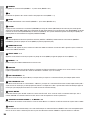
1
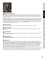
CHANNELS
Overview of the input channels (CHANNEL 1 - 8) and the line outputs (MASTER 1 & 2).
2
EQ
Equalizer setting for the input channels and channel groups (GROUP 1-5).
3
MATRIX
Individual routing for the input channels (CHANNEL 1 - 8) and the line outputs (MASTER 1 & 2).
4
SYSTEM
Set threshold for activation of a channel (THRESHOLD), hold time (HOLD TIME) and gain limits, panel lock (PANEL LOCK), configuration as a
master or slave unit (DEVICE MODE), maximum number of open channels (MAX. OPEN CH), IP address (DEVICE IP), password administration
(USER), global presets and to reset the unit (FACTORY SETTINGS).
5
MENU
Saving and recalling user settings (SAVE FILE / OPEN FILE), connecting and disconnecting a connection (CONNECT / DISCONNECT), managing
the channel group (GROUP) and exiting the program (EXIT).
6
CONNECTION ON / OFF
If the “ON” button is highlighted in yellow, the connection between automixer and computer is established. If the “OFF” button is highlighted
in yellow, the connection between automixer and computer is severed.
7
SINGLE / GROUP 1 - 5
Showing the input channels that are not associated with a channel group (SINGLE), and showing the channel groups (GROUP 1-5).
8
CHANNEL 1 - 8
By double-clicking, the name of the channel can be changed individually.
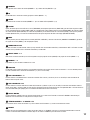
9
EQUALIZER
Graphical representation of the equalizer setting and button to access the 5-band parametric equalizer of the input channels 1 to 8 or 15-band
parametric equalizer of the output channels Master 1 and 2 (single click with the left mouse button).
10
LINE / MIC CHANNEL 1 - 8
Switching the input channels from line to microphone sensitivity and vice versa (single click with the left mouse button). The yellow-highlighted
button shows the option currently active.
11
LINE / MIC MASTER 1 & 2
Switching the output level of the line outputs Master 1 and Master 2 (single click with the left mouse button). The blue-highlighted button
shows the option currently active (LINE = output signal with line level, e.g. for the line input of a power amplifier / MIC = output signal level
attenuated by 20 dB, for example for the microphone input of a mixer).
12
ACTIVE / WAITING
The yellow-highlighted “ACTIVE” button indicates which of the input channels is activated. If a channel is not activated, the message “WAITING”
is greyed out on the screen. By activating the priority function, the corresponding channel is activated permanently.
13
LEVEL METER CHANNEL 1 - 8 / MASTER 1 & 2
The level meters for the input channels 1 to 8 and the line outputs Master 1 and 2 provide a clear overview of the levels.
14
PRIORITY
Button for the priority function of the input channels. By clicking on the “PRIORITY” button, the corresponding channel is given priority over
the other channels. The button will change its colour to yellow. By re-clicking on “PRIORITY”, the priority function is disabled.

ITALIANOPOLSKIESPAÑOL
FRANCAISDEUTSCHENGLISH
15
15
MASTER EQ MASTER 1 & 2
Button to access the 15-band parametric equalizer of the output channels Master 1 and 2 (single click with the left mouse button).
16
PHANTOM CHANNEL 1 - 8
Button for the 48 V phantom power of the input channels. By clicking on the “PHANTOM” button, the phantom power of the corresponding
channel is enabled or disabled. If the phantom power is enabled, the button is highlighted in yellow, if the phantom power is disabled, the
button is greyed out.
17
LIMITER MASTER 1 & 2
Button to access the limiter for the output channels Master 1 and 2 (single click with the left mouse button).
18
MUTE CHANNEL 1 - 8 / MASTER 1 & 2
Button for the mute function of the input channels 1 to 8 and the line outputs Master 1 and 2. By clicking on the “MUTE” button, the mute
function of the corresponding channel is enabled or disabled. If the mute function is enabled, the button is highlighted in red, if the mute
function is disabled, the button is greyed out.
19
GAIN CHANNEL 1 - 8
Set the input gain of the input channels using the mouse (click, hold, and drag).
20
GAIN MASTER 1 & 2
Set the output gain of the line outputs Master 1 and 2 using the mouse (click, hold, and drag).
21
GAIN ANZEIGE CHANNEL 1 - 8
Displays the input gain of the input channels 1 to 8 in dB.
22
GAIN ANZEIGE MASTER 1 & 2
Displays the output gain of the line outputs Master 1 and 2 in dB.
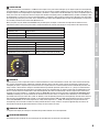
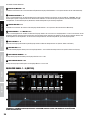
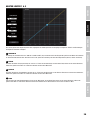
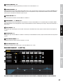
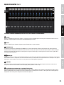
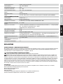
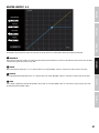
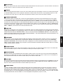
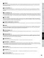
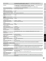
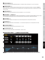
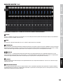
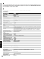
EQUALIZER CHANNEL 1 - 8 (EDIT EQ)
1
2
3
4 5
10
9
8
7
6
11
5-BAND FULLY PARAMETRIC EQUALIZER WITH SEPARATE HIGH-PASS FILTER AND VARIABLE QUALITY OF FILTER AND FILTER
CHARACTERISTICS

16
DEUTSCHFRANCAIS
ESPAÑOL
ENGLISH
ITALIANO POLSKI
1
CHANNELS 1 - 8
Button to access the 5-band parametric equalizer of the input channels 1 to 8. Click on the button of the selected channel to adjust the
equalizer settings. The colour of the button changes to yellow.
2
COPY EQ
Copying the equalizer settings of one input channel to another. Click on the button (N°1) of the channel to overwrite its equalizer (button of
the selected channel changes to yellow). Choose the channel under “COPY FROM”, whose equalizer settings you want to copy and confirm
by clicking “OK”. Now, in the open window, click on “OK” to complete the copy operation, or on “Cancel” to cancel the operation.
3
BYPASS
Click “BYPASS” to disable the equalizer and high-pass filter and once more to re-enable both (sound comparison before - after). If the
equalization and high-pass filter are disabled, the “BYPASS” button is highlighted in yellow.
4
RESET
To reset the equalizer and high-pass filter, click on “RESET”. This operation is not reversible.
5
HPF
High-pass filter (low frequency cut-off) with adjustable cut-off frequency of 35 Hz to 150 Hz. Click the “ON” button to select the high-pass filter,
click “OFF” to disable it. The button of the respective option is highlighted in yellow. Use the virtual fader to adjust the cut-off frequency.
6
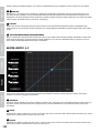
FREQUENCY (HZ)
The frequency to adjust for each individual source of the 5-band equalizer can be chosen individually from 20 Hz to 20,000 Hz. For this
purpose, use the frequency field to enter the desired frequency, or the arrow buttons, next to the frequency field. Frequency and Gain can be
changed at the same time using one of the 5 points in the graphic representation of the frequency curve (click, hold and drag).
7 8
GAIN (DB)
The gain (+/-15 dB) of the respective frequency band is achieved by means of direct entry into the gain field using the arrow buttons next to
the gain field, or through the use of the virtual fader (N°8). Frequency and Gain can be changed at the same time using one of the 5 points
in the graphic representation of the frequency curve (click, hold and drag).
9
Q-FACTOR
The value of the Q factor of the respective filter (filter quality) can be entered directly into the corresponding input field, or by using the
arrow buttons to the right of the input field (Q-factor 0.3 to 20).
10
EQ TYPE
Using the mouse, select the desired filter characteristics of the respective EQ band (EQ = bell filter, LowShelf = cow tail filter low, HighShelf
= cow tail filter high).
11
GRAPHICAL EQUALIZER DISPLAY
The graphical representation of the EQ curve is used for quick and clear overview of the equalizer settings. Frequency and Gain can be
changed at the same time using the 5 points in the graphic representation of the frequency curve (click, hold and drag). Each dot represents
a frequency band.

ITALIANOPOLSKIESPAÑOL
FRANCAISDEUTSCHENGLISH
17
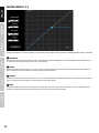
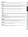
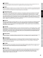
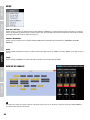
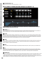
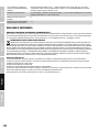
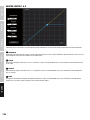
EQUALIZER MASTER 1 & 2
1
2
4
3
7
5
6
15-BAND FULLY PARAMETRIC EQUALIZER WITH BELL FILTER AND VARIABLE QUALITY OF FILTER
1
BYPASS
Click on “BYPASS” to disable the equalizer and high-pass filter and once more to re-enable both (sound comparison before - after). If the
equalizer is disabled, the “BYPASS” button is highlighted in blue.
2
RESET
To reset the equalizer, click on “RESET”. This operation is not reversible.
3
FREQUENZ (HZ)
The frequency to adjust for each individual source of the 15-band equalizer can be chosen individually from 20 Hz to 20,000 Hz. For this
purpose, use the frequency field to enter the desired frequency, or the arrow buttons, next to the frequency field. Frequency and Gain can be
changed at the same time using one of the 15 points in the graphic representation of the frequency curve (click, hold and drag).
4 5
GAIN (DB)
The gain (+/-15 dB) of the respective frequency band is achieved by means of direct entry into the gain field using the arrow buttons next to
the gain field, or through the use of the virtual fader (N°5). Frequency and Gain can be changed at the same time using one of the 15 points
in the graphic representation of the frequency curve (click, hold and drag).
6
Q-FACTOR
The value of the Q factor of the respective filter (filter quality) can be entered directly into the corresponding input field, or by using the
arrow buttons to the right of the input field (Q-factor 0.3 to 20).
7
GRAPHICAL EQUALIZER DISPLAY
The graphical representation of the EQ curve is used for quick and clear overview of the equalizer settings. Frequency and Gain can be
changed at the same time using the 5 points in the graphic representation of the frequency curve (click, hold and drag). Each dot represents
a frequency.

18
DEUTSCHFRANCAIS
ESPAÑOL
ENGLISH
ITALIANO POLSKI
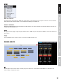
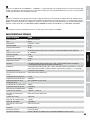
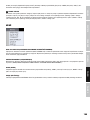
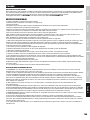
MASTER LIMITER 1 & 2
1
2
3
4
3
The limiter (peak limiter) is used to limit peaks in the audio signal of the line outputs. For this purpose, the following parameter settings are available.
1
THRESHOLD
Setting the threshold value from -80 dB to 19.9 dB, and to OFF (off). Use the arrow buttons in the threshold field to enter the desired value,
or use the point in the graph using the mouse (click, hold and drag).
2
ATTACK
Set the Attack Time (response time) from 1 ms to 2 s. Place the mouse pointer on the attack field, then click with the left mouse button to
select the desired value and confirm by clicking again with the left mouse button.
3
RELEASE
Set the Release Time (release time) from 10 ms to 2 s. Place the mouse pointer on the Release field, then click with the left mouse button to
select the desired value and confirm by clicking again with the left mouse button.
4
RATIO
To adjust the ratio (ratio), place the mouse pointer on the Ratio field, then click with the left mouse button to select the desired value and
confirm by clicking again with the left mouse button. The usual value for a limiter function is INF:1.

ITALIANOPOLSKIESPAÑOL
FRANCAISDEUTSCHENGLISH
19
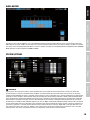
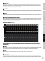
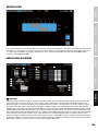
AUDIO MATRIX
Each of the 8 input channels (INPUTS 1-8) can be individually routed to the two line outputs Master 1 and 2 using the audio matrix of the
AM8 automatic mixer (M1 and M2). To select which input channel should be routed to which of the two line outputs, and which one should
not, simply click on the appropriate button. When a channel is routed to an output, the corresponding button is highlighted in blue (CHANNEL
OPEN), otherwise, it will be greyed out (CHANNEL CLOSED).
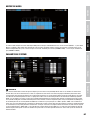
SYSTEM SETTINGS
3
1
2
4
5
6
7
8
9
10
1
THRESHOLD
Input channels with a signal level under a certain threshold value can be muted with the assistance of this function. This means that
the transmission of a channel’s background noise, feedback or unwanted comb filter effects from other active channels are effectively
suppressed and intelligibility of speech is improved. Input channels that have a signal level over a certain threshold value are automatically
activated. The rotary encoder is deactivated for setting the threshold value during automatic operation (“AUTO” button highlighted yellow).
The threshold value is automatically adjusted to the volume of the surrounding sounds. Manual setting of the threshold value (-60 dB to 0
dB) for automatic activation of the input channels is done separately for each channel (“CH SYNC” button greyed out) or for all channels
simultaneously (“CH SYNC” button highlighted yellow). If you click on “MAN” (“MAN” button highlighted yellow) and then select the desired
channel and threshold value in the drop-down menu, background noise will not automatically activate an input channel, but activation of a
channel by a speaker etc. is possible. Set the hold time of the activated channel by clicking on “HOLD TIME” in the drop-down menu and
then selecting the value of your choice (0 - 2000 ms). The channel remains active for the duration of the set hold time, even if the audio
signal falls silent. This means that a different channel can only become active after the end of the hold time.

20
DEUTSCHFRANCAIS
ESPAÑOL
ENGLISH
ITALIANO POLSKI
2
MAX. OPEN CH
To set the maximum number of simultaneously active input channels on the drop-down menu, select the desired number and click “OK”. In
the opening window, click again on “OK”.
3
DEVICE IP
The IP address of the device is factory set to 192.168.1.88. To change the IP address (e.g., for daisy-chaining multiple AM8 automatic
mixer), click on the address field, change the number of the last digit (e.g. 192.168.1.89) and click “OK”. In the opening window, click again
on “OK”. Restart the software and reconnect the device to the software.
4
USERNAME AND PASSWORD
For managing and editing the software, 2 users with different password-protected access rights can be set up (“admin” and “user”). The user
“admin” has access to all menu items in the software, the user “user” to all menu items except “MATRIX” and “SYSTEM”. The factory preset
password for both users (USER PSW) is “000000” (six times the number zero). The password of the user who is currently logged on to the AM8
automatic mixer can be changed in the following ways: Click in the field for the old password “OLD PSW” and enter the old password. Now
enter the new password (maximum 6 characters) in the “NEW PSW” field and again in the field “CONFIRM PSW” and confirm by clicking on the
“CHANGE USER” button. In the opening window, click “OK”, reconnect the device to the software (MENU-> CONNECT) and log on using the new
user password.
5
PANEL LOCK
To protect the device from accidental or unauthorised operation there are 3 lock modes available to block the operating elements of the AM8
automatic mixer (the “POWER” operating element cannot be blocked). Click with the left mouse button on the “PANEL LOCK” field in the
drop-down menu and select the desired lock mode (ALL FUNCTIONS LOCKED = all operating elements locked, GAIN/MAIN VOL AVAILABLE
= only channel and master rotary encoders unlocked, MAIN VOL AVAILABLE = only master rotary encoder unlocked). To enable all operating
elements again, select “OFF”.
6
DEVICE MODE
When using a single AM8 automatic mixer, it must be configured as a master unit. When daisy-chaining up to 16 AM8 automatic mixers using
the LINK IN / LINK OUT interface on the rear panel of the device (see point 14 CONNECTIONS, CONTROLS, AND INDICATORS), the device serving
as the master unit needs to be configured as the master unit. Click the “MAST” button with the left mouse button (the “MAST” button will be
highlighted yellow). All other AM8 automatic mixers in the audio system will be configured as slave units. Click the “SLAVE” button with the left
mouse button (the “SLAVE” button will be highlighted yellow).
7
FACTORY SETTINGS
To reset all settings, such as equalizers and routing, to the default settings, click the “RESTORE” button with the left mouse button. To
confirm the operation, click “YES” in the pop-up window, to cancel click “NO”.
8
NOM ATTENUATION
Automatic level reduction of the master signal to prevent feedback in the event of the simultaneous activation of two or more channels (see
menu point MAX. OPEN CH). Click the “ON” button to activate the function (“ON” button highlighted yellow). The simultaneous activation of 2
channels automatically reduces the master signal by 3 dB, 4 channels by 6 dB, and 8 channels by 9 dB.
9
GAIN LIMITS
This function allows the lower and upper limit adjustment range of the channel pre-amplification GAIN to be separately set on each channel.
Specify the desired value as a whole number in the input fields UPPER (upper limit) and LOWER (lower limit) then click on “OK”. The setting
can be done individually for each channel.
10
GLOBAL PRESETS
Settings across all levels can saved as one of 5 presets and retrieved later. Make the settings as usual and then save them as one of the
presets 1 to 5 by clicking on the drop-down menu of the desired preset, selecting “SAVE” and then clicking on the “OK” button. To retrieve
an already saved preset, click on the drop-down menu of the saved preset, select “RECALL” and then click “OK”. To delete a preset, select
“RESET” in the respective drop-down menu and click on “OK”.
La pagina si sta caricando...
La pagina si sta caricando...
La pagina si sta caricando...
La pagina si sta caricando...
La pagina si sta caricando...
La pagina si sta caricando...
La pagina si sta caricando...
La pagina si sta caricando...
La pagina si sta caricando...
La pagina si sta caricando...
La pagina si sta caricando...
La pagina si sta caricando...
La pagina si sta caricando...
La pagina si sta caricando...
La pagina si sta caricando...
La pagina si sta caricando...
La pagina si sta caricando...
La pagina si sta caricando...
La pagina si sta caricando...
La pagina si sta caricando...
La pagina si sta caricando...
La pagina si sta caricando...
La pagina si sta caricando...
La pagina si sta caricando...
La pagina si sta caricando...
La pagina si sta caricando...
La pagina si sta caricando...
La pagina si sta caricando...
La pagina si sta caricando...
La pagina si sta caricando...
La pagina si sta caricando...
La pagina si sta caricando...
La pagina si sta caricando...
La pagina si sta caricando...
La pagina si sta caricando...
La pagina si sta caricando...
La pagina si sta caricando...
La pagina si sta caricando...
La pagina si sta caricando...
La pagina si sta caricando...
La pagina si sta caricando...
La pagina si sta caricando...
La pagina si sta caricando...
La pagina si sta caricando...
La pagina si sta caricando...
La pagina si sta caricando...
La pagina si sta caricando...
La pagina si sta caricando...
La pagina si sta caricando...
La pagina si sta caricando...
La pagina si sta caricando...
La pagina si sta caricando...
La pagina si sta caricando...
La pagina si sta caricando...
La pagina si sta caricando...
La pagina si sta caricando...
La pagina si sta caricando...
La pagina si sta caricando...
La pagina si sta caricando...
La pagina si sta caricando...
La pagina si sta caricando...
La pagina si sta caricando...
La pagina si sta caricando...
La pagina si sta caricando...
La pagina si sta caricando...
La pagina si sta caricando...
La pagina si sta caricando...
La pagina si sta caricando...
La pagina si sta caricando...
La pagina si sta caricando...
La pagina si sta caricando...
La pagina si sta caricando...
La pagina si sta caricando...
La pagina si sta caricando...
La pagina si sta caricando...
La pagina si sta caricando...
La pagina si sta caricando...
La pagina si sta caricando...
La pagina si sta caricando...
La pagina si sta caricando...
La pagina si sta caricando...
La pagina si sta caricando...
La pagina si sta caricando...
La pagina si sta caricando...
La pagina si sta caricando...
La pagina si sta caricando...
La pagina si sta caricando...
La pagina si sta caricando...
La pagina si sta caricando...
La pagina si sta caricando...
La pagina si sta caricando...
La pagina si sta caricando...
La pagina si sta caricando...
La pagina si sta caricando...
La pagina si sta caricando...
La pagina si sta caricando...
La pagina si sta caricando...
La pagina si sta caricando...
La pagina si sta caricando...
La pagina si sta caricando...
La pagina si sta caricando...
La pagina si sta caricando...
La pagina si sta caricando...
La pagina si sta caricando...
La pagina si sta caricando...
La pagina si sta caricando...
La pagina si sta caricando...
La pagina si sta caricando...
La pagina si sta caricando...
La pagina si sta caricando...
La pagina si sta caricando...
La pagina si sta caricando...
-
 1
1
-
 2
2
-
 3
3
-
 4
4
-
 5
5
-
 6
6
-
 7
7
-
 8
8
-
 9
9
-
 10
10
-
 11
11
-
 12
12
-
 13
13
-
 14
14
-
 15
15
-
 16
16
-
 17
17
-
 18
18
-
 19
19
-
 20
20
-
 21
21
-
 22
22
-
 23
23
-
 24
24
-
 25
25
-
 26
26
-
 27
27
-
 28
28
-
 29
29
-
 30
30
-
 31
31
-
 32
32
-
 33
33
-
 34
34
-
 35
35
-
 36
36
-
 37
37
-
 38
38
-
 39
39
-
 40
40
-
 41
41
-
 42
42
-
 43
43
-
 44
44
-
 45
45
-
 46
46
-
 47
47
-
 48
48
-
 49
49
-
 50
50
-
 51
51
-
 52
52
-
 53
53
-
 54
54
-
 55
55
-
 56
56
-
 57
57
-
 58
58
-
 59
59
-
 60
60
-
 61
61
-
 62
62
-
 63
63
-
 64
64
-
 65
65
-
 66
66
-
 67
67
-
 68
68
-
 69
69
-
 70
70
-
 71
71
-
 72
72
-
 73
73
-
 74
74
-
 75
75
-
 76
76
-
 77
77
-
 78
78
-
 79
79
-
 80
80
-
 81
81
-
 82
82
-
 83
83
-
 84
84
-
 85
85
-
 86
86
-
 87
87
-
 88
88
-
 89
89
-
 90
90
-
 91
91
-
 92
92
-
 93
93
-
 94
94
-
 95
95
-
 96
96
-
 97
97
-
 98
98
-
 99
99
-
 100
100
-
 101
101
-
 102
102
-
 103
103
-
 104
104
-
 105
105
-
 106
106
-
 107
107
-
 108
108
-
 109
109
-
 110
110
-
 111
111
-
 112
112
-
 113
113
-
 114
114
-
 115
115
-
 116
116
-
 117
117
-
 118
118
-
 119
119
-
 120
120
-
 121
121
-
 122
122
-
 123
123
-
 124
124
-
 125
125
-
 126
126
-
 127
127
-
 128
128
-
 129
129
-
 130
130
-
 131
131
-
 132
132


LD Systems AM8 Manuale utente
- Categoria
- Mixer audio
- Tipo
- Manuale utente
- Questo manuale è adatto anche per
in altre lingue
- English: LD Systems AM8 User manual
- français: LD Systems AM8 Manuel utilisateur
- español: LD Systems AM8 Manual de usuario
- Deutsch: LD Systems AM8 Benutzerhandbuch
- polski: LD Systems AM8 Instrukcja obsługi
Documenti correlati
Altri documenti
-
Yamaha 02R96 Manuale del proprietario
-
Yamaha DM2000 Manuale del proprietario
-
-
-
-
-
-
-
AKG AS 8 TC Manuale del proprietario
-
Optimus PM-604 Manuale utente