
DCT1
direct connection energy transducer
22/06/2023
USER MANUAL

Contents
2 DCT1 - User manual | 22/06/2023 | CARLO GAVAZZI Controls SpA
This manual 3
DCT1 4
Introduction 4
Description 4
Available versions 6
Evaluation certificate 6
Configuration software 6
Use 7
Maintenance mode and cable loss compensation 7
Settings 7
Reset 7
Commissioning 8
Modbus RTU 8
SML 8
Essential information 9
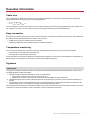
Cable loss 9
Easy connection 9
Temperature monitoring 9
Signature 9
Introduction 9
Modbus RTU versions 10
SML version 10
Run-hour meters 10
Maintenance and disposal 11
Troubleshooting 11
Communication problems 11
Cleaning 11
Responsibility for disposal 11
Download 11
Symbols 12

DCT1 - User manual | 22/06/2023 | CARLO GAVAZZI Controls SpA 3
This manual
Information property
Copyright © 2023, CARLO GAVAZZI Controls SpA
All rights reserved in all countries.
CARLO GAVAZZI Controls SpA reserves the right to apply modifications or make improvements to the relative documentation
without the obligation of advance notice.
Safety messages
The following section describes the warnings related to user and device safety included in this document:
NOTICE: indicates obligations that if not observed may lead to damage to the device.
CAUTION! Indicates a risky situation which, if not avoided, may cause data loss.
IMPORTANT: provides essential information on completing the task that should not be neglected.
General warnings
This manual is an integral part of the product and accompanies it for its entire working life. It should be consulted for all
situations tied to configuration, use and maintenance. For this reason, it should always be accessible to operators.
NOTICE: no one is authorized to open the analyzer. This operation is reserved exclusively for CARLO GAVAZZI technical
service personnel.
Protection may be impaired if the instrument is used in a manner not specified by the manufacturer.
Service and warranty
In the event of malfunction, fault, requests for information or to purchase accessory modules, contact the CARLO GAVAZZI
branch or distributor in your country. Installation and use of analyzers other than those indicated in the provided instructions void
the warranty.

DCT1
Introduction
DCT1 is a direct connection energy transducer for DC systems up to 1000 V dc and current up to 600 A dc. Dedicated versions can
implement three different communication protocols:
lModbus RTU, or
lModbus RTU with either 256-bit or 384-bit signature, or
lSML with 385-bit signature
Furthermore, thanks to the evaluation certificate, certified DCT1 versions are suitable for installation on electric vehicle chargers
that requires Eichrecht approval.
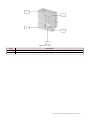
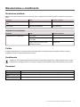
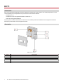
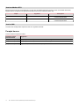
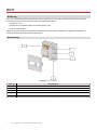
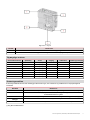
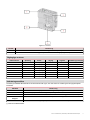
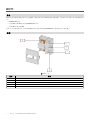
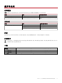
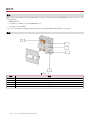
Description
Figure 1 DCT1 front
Area Description
AVoltage/current inputs
BLEDs
CPower supply
DRS485 port
ECurrent inputs
4 DCT1 - User manual | 22/06/2023 | CARLO GAVAZZI Controls SpA


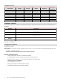
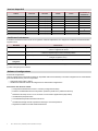
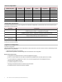
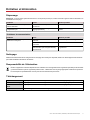
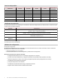
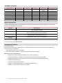
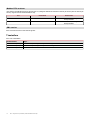
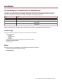
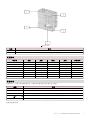
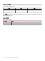
Available versions
Part number Voltage Current Output Signature Evaluation
certificate
DCT1A60V10LS1X 150…1000 V 6-120 (600) A Modbus RTU - -
DCT1A60V10LS2EC 150…1000 V 6-120 (600) A Modbus RTU 256 bit x
DCT1A60V10LS3EC 150…1000 V 6-120 (600) A Modbus RTU 384 bit x
DCT1A60V10LK1EC 150…1000 V 6-120 (600) A SML 384 bit x
DCT1A30V10LS1X 150…1000 V 2.5-50 (300) A Modbus RTU - -
DCT1A30V10LS2EC 150…1000 V 2.5-50 (300) A Modbus RTU 256 bit x
DCT1A30V10LS3EC 150…1000 V 2.5-50 (300) A Modbus RTU 384 bit x
DCT1A30V10LK1EC 150…1000 V 2.5-50 (300) A SML 384 bit x
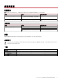
Evaluation certificate
The evaluation certificate is provided by an independent notify body, which performs tests and verifications to fulfill the following
standards:
Standard Description
IEC 62052-11 Electricity metering equipment (AC) – General requirements, tests and test conditions – Part 11:
Metering equipment
IEC62052-31 Electricity metering equipment (AC) - General requirements, tests and test conditions - Part 31:
Product safety requirements and tests
IEC62053-41* Electricity metering equipment - Particular requirements - Part 41: Static meters for DC energy
(classes 0,5 and 1)
VDE-AR-E 2418-3-100
Annex A
Electric mobility - Measuring systems for charging stations
WELMEC 7.2 Software Guide (Measuring Instruments Directive 2014/32/EU)
(*) Except for durability test
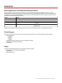
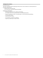
Configuration software
Configuration software
UCS is the DCT1 configuration software available in desktop version. It may connect to DCT1 via RS485 (Modbus RTU protocol).
UCS allows to:
lset up the unit (online or offline);
ldisplay the system state for diagnostic and setup verification purposes
Overview of the UCS functions:
lSetting up the system with DCT1 connected (online setup)
lEnter maintenance mode and set cable loss parameters (cable resistance)
lDefining the setup with DCT1 non connected, then applying it later (offline setup)
lDisplaying the main measurements
lCheck temperature on the shunt
lDisplaying overrange and overtemperature warnings
lRecording the measurements of selected variables
6 DCT1 - User manual | 22/06/2023 | CARLO GAVAZZI Controls SpA

DCT1 - User manual | 22/06/2023 | CARLO GAVAZZI Controls SpA 7
Use
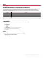
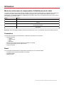
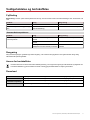
Maintenance mode and cable loss compensation
Maintenance mode is a special status of the meter where the cable loss parameter can be changed. To change cable loss
parameters using UCS software, follow the wizard available in the section Maintenance. To change cable loss parameters using
Modbus commands follow this procedure, referring to the Modbus protocol:
Step Action
1 Power on DCT1
2 Send Maintenance command by 5 seconds from power on.
3 Send Time sync command by 10 seconds from previous command
4 Set new Resistance value by 10 seconds from previous command
Note: in certified models (part numbers ending with “EC”), this parameter can only be changed 50 times.
Settings
The following parameters can be set using UCS or Modbus commands:
lRS485 parameters
lAddress
lBaudrate
lParity
lStop bit
lEasy connection enabling (only non-certified models)
lStart up current for run hour meters
lDevice tag
Reset
The following reset commands are available only through modbus command
lTotal meters (only non-certified models)
lPartial meters
lFactory settings

Commissioning
Modbus RTU
Modbus RTU communication port is used to transmit data to a Modbus master.
For further information about Modbus RTU communication refer to the communication protocol.
SML
For further information about SML communication refer to the communication protocol.
8 DCT1 - User manual | 22/06/2023 | CARLO GAVAZZI Controls SpA

DCT1 - User manual | 22/06/2023 | CARLO GAVAZZI Controls SpA 9
Essential information
Cable loss
DCT1 implements the cable loss correction factor, considering the resistance of the cable in the measurement of voltage and
power (and therefore also energy). They are calculated as follows:
lV = Vmeas- R·lmeas
lP=Vmeas* Imeas-RImeas^2
Thus, the cable loss correction factor allows a more accurate measurement of the actual energy that flows from the charger to the
car. Cable loss can only be set up in maintenance mode, through the dedicated procedure described above.
Easy connection
Easy connection function allows ignoring current and power direction, increasing only the positive energy meter, and not affecting
the negative one when bidirectionality is not needed. The function is:
lavailable only for the non-certified version of the device
ldisabled by default and can be enabled using UCS or Modbus command.
Temperature monitoring
DCT1 monitors the temperature of the shunt constantly; through the Modbus RTU the user can control two parameters:
lthe temperature of the upper part of the shunt and
lthe temperature of the lower part of the shunt.
The shunt should never exceed 120 degrees to avoid damage to the electronic components. The temperature is measured at two
different points because the shunt can connect to conductors with different resistance.
Signature
Introduction
The signature, available in certificate versions, is a 256-bit or 384-bit data field that guarantees data authenticity. The process of
the digital signature includes three stages:
1. Generation stage: an algorithm generates a couple of correlated keys,
lthe private key, which is known only by the DCT1 itself, and
lthe public key, lasered on the front of the meter (QR code) and available through Modbus RTU
2. Authentication stage: the set of data collected by the DCT1 is signed using the private key, which asserts the authenticity of
the data,
3. Integrity stage: the data can be verified by the user only through the public key that matches the private one. Otherwise, the
system leads to an error. It guarantees the integrity of the data reported by the device.
DCT1 implements this procedure to ensure the information it reports is not corrupted by an external system because no one apart
from the DCT1 knows the private key, which is necessary to verify the authenticity of the data.

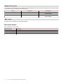
Modbus RTU versions
In EC versions with Modbus RTU port, in addition to the standard Modbus map, DCT1 provides an additional set of data, including
a 256-bit (S2 version) or a 384-bit (S3 version) signature.
Step Signature Description
S2 256-bit 256 bit ECDSA SHA 256, using curve
brainpoolP256r1
S3 384-bit 384 bit ECDSA SHA 384, using curve
brainpoolP384r1
SML version
The SML version is available only with 384-bit signature.
Run-hour meters
DCT1 provides 3 run-hour meters:
Run-hour meter Increases...
Run hour meter (kWh+) when the power is positive and the current above I_tr
Run hour meter (kWh-) when the power is positive and the current below -I_tr
Run hour meter (ON time) always when DCT1 is ON.
10 DCT1 - User manual | 22/06/2023 | CARLO GAVAZZI Controls SpA

DCT1 - User manual | 22/06/2023 | CARLO GAVAZZI Controls SpA 11
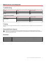
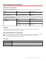
Maintenance and disposal
Troubleshooting
Note: in case of other malfunctions or of any failure, please contact the CARLO GAVAZZI branch or the distributor for your country
Problem Cause Possible solution
The values are not the expected ones Electrical connections are incorrect Verify the connections
Exported energy meters (kWh-) don’t
increase
Measurement mode is set to A (default
setting)
Set Measurement mode from A to B in
UCS
Communication problems
Problem Cause Possible solution
No communication can be established
with the analyser
Communication settings are incorrect Check the set parameters
Communication connections are incorrect Verify the connections
The settings of the communication device
(third-party PLC or software) are incorrect
Check the communication with the UCS
software
Cleaning
Disconnect the power supply and loads before cleaning. To keep the device clean, use a slightly wet cloth. Never use abrasives or
solvents.
Responsibility for disposal
Dispose of the unit by separately collecting its materials and bringing them to the facilities specified by government
authorities or by local public bodies. Proper disposal and recycling will help preventing potentially harmful consequences
for the environment and for people.
Download
This manual https://gavazziautomation.com/images/PIM/MANUALS/ENG/DCT1_IM_USE.pdf
DCT1 datasheet https://gavazziautomation.com/images/PIM/DATASHEET/ENG/DCT1_DS_ENG.pdf
DCT1 installation manual https://gavazziautomation.com/images/PIM/MANUALS/ENG/DCT1_IM_INST.pdf
UCS Software https://www.gavazziautomation.com/images/PIM/OTHERSTUFF/ucs.zip

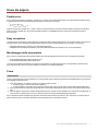
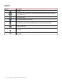
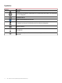
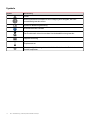
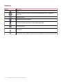
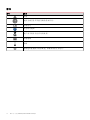
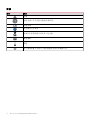
Symbols
Symbol Description
Danger
Provides essential information on completing the task that should not be
neglected
Manual symbol
Safety sign notice
The product is not to be discarded with normal household waste
Double insulation
Single phase
The indicated measurement is strongly recommended for the correct functioning
of the device
12 DCT1 - User manual | 22/06/2023 | CARLO GAVAZZI Controls SpA


CARLO GAVAZZI Controls SpA
via Safforze, 8
32100 Belluno (BL) Italy
www.gavazziautomation.com
info: +39 0437 355811
fax: +39 0437 355880
DCT1 - User manual
22/06/2023 | Copyright © 2023

DCT1
Convertitore di segnale a connessione diretta
22/06/2023
MANUALE UTENTE

Indice
2 DCT1 - Manuale utente | 22/06/2023 | CARLO GAVAZZI Controls SpA
Questo manuale 3
DCT1 4
Introduzione 4
Descrizione 4
Versioni disponibili 6
Certificato di valutazione 6
Software di configurazione 6
Uso 7
Modalità Manutenzione e compensazione perdita cavo 7
Impostazioni 7
Reset 7
Messa in servizio 8
Modbus RTU 8
SML 8
Cose da sapere 9
Perdita cavo 9
Easy connection 9
Monitoraggio della temperatura 9
Firma 9
Introduzione 9
Versioni Modbus RTU. 10
Versione SML 10
Contaore 10
Manutenzione e smaltimento 11
Risoluzione problemi 11
Problemi di comunicazione 11
Pulizia 11
Smaltimento 11
Download 11
Simboli 12

DCT1 - Manuale utente | 22/06/2023 | CARLO GAVAZZI Controls SpA 3
Questo manuale
Proprietà delle informazioni
Copyright © 2023, CARLO GAVAZZI Controls SpA
Tutti i diritti riservati in tutti i paesi.
CARLO GAVAZZI Controls SpA si riserva il diritto di apportare modifiche o correzioni alla relativa documentazione senza alcun
obbligo di preavviso.
Messaggi di sicurezza
La sezione seguente descrive gli avvisi relativi alla sicurezza degli utenti e dei dispositivi presenti in questo documento:
AVVISO: indica obblighi che se non osservati possono portare al danneggiamento del dispositivo.
ATTENZIONE! Indica una situazione pericolosa che, se non evitata, può causare la perdita di dati.
IMPORTANTE: offre indicazioni essenziali al completamento del compito che non devono essere trascurate.
Avvertenze generali
Questo manuale è parte integrante del prodotto e accompagna il prodotto per tutta la sua vita. Deve essere consultato in
tutte le situazioni connesse alla configurazione, all'uso e alla manutenzione. Per tale ragione dovrebbe essere sempre
accessibile agli operatori.
AVVISO: nessuno è autorizzato ad aprire l’analizzatore. Questa operazione può essere eseguita soltanto dal personale di
assistenza tecnica di CARLO GAVAZZI.
La protezione può essere compromessa se lo strumento viene usato in un modo non specificato dal costruttore.
Servizio e garanzia
In caso di malfunzionamenti, guasti, richieste di informazioni, o acquisto di moduli accessori, contattare la filiale CARLO GAVAZZI
o il distributore nel proprio paese. L’installazione e l’uso dell’analizzatore diversi da quanto indicato nelle istruzioni fornite
invalidano la garanzia.

DCT1
Introduzione
DCT1 è un convertitore di segnale a connessione diretta per sistemi CC fino a 1000 V cc e corrente fino a 600 A cc. Specifiche
versioni possono implementare tre diversi protocolli di comunicazione:
lModbus RTU, o
lModbus RTU con firma a 256 bit o 384 bit, o
lSML con firma a 385 bit
Grazie al certificato di valutazione, inoltre, le versioni DCT1 possono essere installate su caricatori per veicoli elettrici che
richiedono l’approvazione Eichrecht.
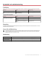
Descrizione
Figura 1 DCT1 Fronte
Area Descrizione
AIngressi tensione/corrente
BLED
CAlimentazione
DPorta RS485
EIngressi di corrente
4 DCT1 - Manuale utente | 22/06/2023 | CARLO GAVAZZI Controls SpA


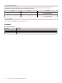
Versioni disponibili
Codice Tensione Corrente Uscita Firma Certificato di
valutazione
DCT1A60V10LS1X 150…1000 V 6-120 (600) A Modbus RTU - -
DCT1A60V10LS2EC 150…1000 V 6-120 (600) A Modbus RTU 256 bit x
DCT1A60V10LS3EC 150…1000 V 6-120 (600) A Modbus RTU 384 bit x
DCT1A60V10LK1EC 150…1000 V 6-120 (600) A SML 384 bit x
DCT1A30V10LS1X 150…1000 V 2.5-50 (300) A Modbus RTU - -
DCT1A30V10LS2EC 150…1000 V 2.5-50 (300) A Modbus RTU 256 bit x
DCT1A30V10LS3EC 150…1000 V 2.5-50 (300) A Modbus RTU 384 bit x
DCT1A30V10LK1EC 150…1000 V 2.5-50 (300) A SML 384 bit x
Certificato di valutazione
Il certificato di valutazione viene fornito da un organismo notificato indipendente, che esegue test e verifiche conformemente alle
seguenti norme:
Standard Descrizione
IEC 62052-11 Apparati per la misura dell'energia elettrica (CA) – Prescrizioni generali, prove e condizioni di prova
– Parte 11: Apparato di misura
IEC62052-31 Apparati per la misura dell'energia elettrica (CA) – Prescrizioni generali, prove e condizioni di prova
– Parte 31: Requisiti e prove di sicurezza del prodotto
IEC62053-41* Apparati per la misura dell'energia elettrica - Prescrizioni particolari - Parte 41: Contatori statici di
energia CC (classi 0,5 e 1)
VDE-AR-E 2418-3-100
Allegato A
Mobilità elettrica - Sistemi di misura per stazioni di ricarica
WELMEC 7.2 Guida al software (Direttiva 2014/32/UE sugli strumenti di misura)
(*) Tranne che per la prova di durata
Software di configurazione
Software di configurazione
UCS è il software per la configurazione del DCT1 disponibile nella versione desktop. Può essere collegato al DCT1 tramite RS485
(protocollo Modbus RTU). Con UCS è possibile:
lconfigurare l'unità (online o offline);
lvisualizzare lo stato del sistema a fini diagnostici e di verifica della configurazione
Panoramica delle funzioni di UCS:
lConfigurazione del sistema con DCT1 connesso (configurazione online)
lEntrare in modalità Manutenzione e impostare i parametri “perdita cavo” (resistenza del cavo)
lDefinizione del setup con DCT1 non connesso e sua successiva applicazione (setup offline)
lVisualizzare le principali misure
lControllo della temperatura massima sullo shunt
lVisualizzazione degli avvisi di superamento del range e di sovratemperatura
lRegistrazione delle misure delle variabili selezionate
6 DCT1 - Manuale utente | 22/06/2023 | CARLO GAVAZZI Controls SpA
La pagina si sta caricando...
La pagina si sta caricando...
La pagina si sta caricando...
La pagina si sta caricando...
La pagina si sta caricando...
La pagina si sta caricando...
La pagina si sta caricando...
La pagina si sta caricando...
La pagina si sta caricando...
La pagina si sta caricando...
La pagina si sta caricando...
La pagina si sta caricando...
La pagina si sta caricando...
La pagina si sta caricando...
La pagina si sta caricando...
La pagina si sta caricando...
La pagina si sta caricando...
La pagina si sta caricando...
La pagina si sta caricando...
La pagina si sta caricando...
La pagina si sta caricando...
La pagina si sta caricando...
La pagina si sta caricando...
La pagina si sta caricando...
La pagina si sta caricando...
La pagina si sta caricando...
La pagina si sta caricando...
La pagina si sta caricando...
La pagina si sta caricando...
La pagina si sta caricando...
La pagina si sta caricando...
La pagina si sta caricando...
La pagina si sta caricando...
La pagina si sta caricando...
La pagina si sta caricando...
La pagina si sta caricando...
La pagina si sta caricando...
La pagina si sta caricando...
La pagina si sta caricando...
La pagina si sta caricando...
La pagina si sta caricando...
La pagina si sta caricando...
La pagina si sta caricando...
La pagina si sta caricando...
La pagina si sta caricando...
La pagina si sta caricando...
La pagina si sta caricando...
La pagina si sta caricando...
La pagina si sta caricando...
La pagina si sta caricando...
La pagina si sta caricando...
La pagina si sta caricando...
La pagina si sta caricando...
La pagina si sta caricando...
La pagina si sta caricando...
La pagina si sta caricando...
La pagina si sta caricando...
La pagina si sta caricando...
La pagina si sta caricando...
La pagina si sta caricando...
La pagina si sta caricando...
La pagina si sta caricando...
La pagina si sta caricando...
La pagina si sta caricando...
La pagina si sta caricando...
La pagina si sta caricando...
La pagina si sta caricando...
La pagina si sta caricando...
La pagina si sta caricando...
La pagina si sta caricando...
La pagina si sta caricando...
La pagina si sta caricando...
La pagina si sta caricando...
La pagina si sta caricando...
La pagina si sta caricando...
La pagina si sta caricando...
La pagina si sta caricando...
La pagina si sta caricando...
La pagina si sta caricando...
La pagina si sta caricando...
La pagina si sta caricando...
La pagina si sta caricando...
La pagina si sta caricando...
La pagina si sta caricando...
La pagina si sta caricando...
La pagina si sta caricando...
La pagina si sta caricando...
La pagina si sta caricando...
La pagina si sta caricando...
La pagina si sta caricando...
La pagina si sta caricando...
La pagina si sta caricando...
La pagina si sta caricando...
La pagina si sta caricando...
La pagina si sta caricando...
La pagina si sta caricando...
La pagina si sta caricando...
La pagina si sta caricando...
La pagina si sta caricando...
La pagina si sta caricando...
La pagina si sta caricando...
La pagina si sta caricando...
La pagina si sta caricando...
La pagina si sta caricando...
La pagina si sta caricando...
La pagina si sta caricando...
-
 1
1
-
 2
2
-
 3
3
-
 4
4
-
 5
5
-
 6
6
-
 7
7
-
 8
8
-
 9
9
-
 10
10
-
 11
11
-
 12
12
-
 13
13
-
 14
14
-
 15
15
-
 16
16
-
 17
17
-
 18
18
-
 19
19
-
 20
20
-
 21
21
-
 22
22
-
 23
23
-
 24
24
-
 25
25
-
 26
26
-
 27
27
-
 28
28
-
 29
29
-
 30
30
-
 31
31
-
 32
32
-
 33
33
-
 34
34
-
 35
35
-
 36
36
-
 37
37
-
 38
38
-
 39
39
-
 40
40
-
 41
41
-
 42
42
-
 43
43
-
 44
44
-
 45
45
-
 46
46
-
 47
47
-
 48
48
-
 49
49
-
 50
50
-
 51
51
-
 52
52
-
 53
53
-
 54
54
-
 55
55
-
 56
56
-
 57
57
-
 58
58
-
 59
59
-
 60
60
-
 61
61
-
 62
62
-
 63
63
-
 64
64
-
 65
65
-
 66
66
-
 67
67
-
 68
68
-
 69
69
-
 70
70
-
 71
71
-
 72
72
-
 73
73
-
 74
74
-
 75
75
-
 76
76
-
 77
77
-
 78
78
-
 79
79
-
 80
80
-
 81
81
-
 82
82
-
 83
83
-
 84
84
-
 85
85
-
 86
86
-
 87
87
-
 88
88
-
 89
89
-
 90
90
-
 91
91
-
 92
92
-
 93
93
-
 94
94
-
 95
95
-
 96
96
-
 97
97
-
 98
98
-
 99
99
-
 100
100
-
 101
101
-
 102
102
-
 103
103
-
 104
104
-
 105
105
-
 106
106
-
 107
107
-
 108
108
-
 109
109
-
 110
110
-
 111
111
-
 112
112
-
 113
113
-
 114
114
-
 115
115
-
 116
116
-
 117
117
-
 118
118
-
 119
119
-
 120
120
-
 121
121
-
 122
122
-
 123
123
-
 124
124
-
 125
125
-
 126
126


CARLO GAVAZZI DCT1A30V10LK1EC Manuale del proprietario
- Tipo
- Manuale del proprietario
- Questo manuale è adatto anche per
in altre lingue
Documenti correlati
-
CARLO GAVAZZI DCT1A30V10LK1EC Manuale del proprietario
-
CARLO GAVAZZI EM530DINAV53XM1X Manuale del proprietario
-
-
-
-
-
-
-
-