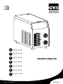
GYS PROGYS 200A PFC Manuale del proprietario
- Tipo
- Manuale del proprietario

75525_V7_02/01/2019
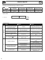
FR
EN
DE
ES
RU
NL
IT
02-08 / 51-56
09-15 / 51-56
16-22 / 51-56
23-29 / 51-56
30-36 / 51-56
37-43 / 51-56
44-50 / 51-56
PROGYS 200A PFC
www.gys.fr
MADE IN FRANCE

2
PROGYS 200A PFC
MADE IN FRANCE
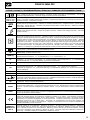
AVERTISSEMENTS - RÈGLES DE SÉCURITÉ
CONSIGNE GÉNÉRALE
Ces instructions doivent être lues et bien comprises avant toute opération.
Toute modication ou maintenance non indiquée dans le manuel ne doit pas être entreprise.
Tout dommage corporel ou matériel dû à une utilisation non-conforme aux instructions de ce manuel ne pourra être
retenu à la charge du fabricant.
En cas de problème ou d’incertitude, consulter une personne qualiée pour manier correctement l’installation.
ENVIRONNEMENT
Ce matériel doit être utilisé uniquement pour faire des opérations de soudage dans les limites indiquées par la plaque
signalétique et/ou le manuel. Il faut respecter les directives relatives à la sécurité. En cas d’utilisation inadéquate ou
dangereuse, le fabricant ne pourra être tenu responsable.
L’installation doit être utilisée dans un local sans poussière, ni acide, ni gaz inammable ou autres substances corrosives
de même pour son stockage. S’assurer d’une circulation d’air lors de l’utilisation.
Plages de température :
Utilisation entre -10 et +40°C (+14 et +104°F).
Stockage entre -20 et +55°C (-4 et 131°F).
Humidité de l’air :
Inférieur ou égal à 50% à 40°C (104°F).
Inférieur ou égal à 90% à 20°C (68°F).
Altitude :
Jusqu’à 1000 m au-dessus du niveau de la mer (3280 pieds).
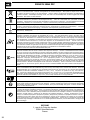
PROTECTIONS INDIVIDUELLE ET DES AUTRES
Le soudage à l’arc peut être dangereux et causer des blessures graves voire mortelles.
Le soudage expose les individus à une source dangereuse de chaleur, de rayonnement lumineux de l’arc, de champs
électromagnétiques (attention au porteur de pacemaker), de risque d’électrocution, de bruit et d’émanations gazeuses.
Pour bien se protéger et protéger les autres, respecter les instructions de sécurité suivantes :
An de se protéger de brûlures et rayonnements, porter des vêtements sans revers, isolants, secs, igni-
fugés et en bon état, qui couvrent l’ensemble du corps.
Utiliser des gants qui garantissent l’isolation électrique et thermique.
Utiliser une protection de soudage et/ou une cagoule de soudage d’un niveau de protection sufsant
(variable selon les applications). Protéger les yeux lors des opérations de nettoyage. Les lentilles de
contact sont particulièrement proscrites.
Il est parfois nécessaire de délimiter les zones par des rideaux ignifugés pour protéger la zone de sou-
dage des rayons de l’arc, des projections et des déchets incandescents.
Informer les personnes dans la zone de soudage de ne pas xer les rayons de l’arc ni les pièces en fusion
et de porter les vêtements adéquats pour se protéger.
Utiliser un casque contre le bruit si le procédé de soudage atteint un niveau de bruit supérieur à la limite
autorisée (de même pour toute personne étant dans la zone de soudage).
Tenir à distance des parties mobiles (ventilateur) les mains, cheveux, vêtements.
Ne jamais enlever les protections carter du groupe froid lorsque la source de courant de soudage est sous
tension, le fabricant ne pourrait être tenu pour responsable en cas d’accident.
Les pièces qui viennent d’être soudées sont chaudes et peuvent provoquer des brûlures lors de leur
manipulation. Lors d’intervention d’entretien sur la torche ou le porte-électrode, il faut s’assurer que
celui-ci soit sufsamment froid en attendant au moins 10 minutes avant toute intervention. Le groupe
froid doit être allumé lors de l’utilisation d’une torche refroidie eau an d’être sûr que le liquide ne puisse
pas causer de brûlures.
Il est important de sécuriser la zone de travail avant de la quitter an de protéger les personnes et les
biens.
FR

3
PROGYS 200A PFC
MADE IN FRANCE
FUMÉES DE SOUDAGE ET GAZ
Les fumées, gaz et poussières émis par le soudage sont dangereux pour la santé. Il faut prévoir une
ventilation sufsante, un apport d’air est parfois nécessaire. Un masque à air frais peut être une solution
en cas d’aération insufsante.
Vérier que l’aspiration est efcace en la contrôlant par rapport aux normes de sécurité.
Attention le soudage dans des milieux de petites dimensions nécessite une surveillance à distance de sécurité. Par
ailleurs le soudage de certains matériaux contenant du plomb, cadmium, zinc ou mercure voire du béryllium peuvent
être particulièrement nocifs, dégraisser également les pièces avant de les souder.
Les bouteilles doivent être entreposées dans des locaux ouverts ou bien aérés. Elles doivent être en position verticale
et maintenues à un support ou sur un chariot.
Le soudage doit être proscrit à proximité de graisse ou de peinture.
RISQUES DE FEU ET D’EXPLOSION
Protéger entièrement la zone de soudage, les matières inammables doivent être éloignées d’au moins
11 mètres.
Un équipement anti-feu doit être présent à proximité des opérations de soudage.
Attention aux projections de matières chaudes ou d’étincelles et même à travers des ssures, elles peuvent être source
d’incendie ou d’explosion.
Éloigner les personnes, les objets inammables et les containers sous pressions à une distance de sécurité sufsante.
Le soudage dans des containers ou des tubes fermés est à proscrire et dans le cas où ils sont ouverts il faut les vider de
toute matière inammable ou explosive (huile, carburant, résidus de gaz …).
Les opérations de meulage ne doivent pas être dirigées vers la source de courant de soudage ou vers des matières
inammables.
BOUTEILLES DE GAZ
Le gaz sortant des bouteilles peut être source de suffocation en cas de concentration dans l’espace
de soudage (bien ventiler).
Le transport doit être fait en toute sécurité : bouteilles fermées et la source de courant de soudage
éteinte. Elles doivent être entreposées verticalement et maintenues par un support pour limiter le
risque de chute.
Fermer la bouteille entre deux utilisations. Attention aux variations de température et aux expositions
au soleil.
La bouteille ne doit pas être en contact avec une amme, un arc électrique, une torche, une pince de
masse ou toutes autres sources de chaleur ou d’incandescence.
Veiller à la tenir éloignée des circuits électriques et de soudage et donc ne jamais souder une bouteille
sous pression.
Attention lors de l’ouverture du robinet de la bouteille, il faut éloigner la tête la robinetterie et s’assurer
que le gaz utilisé est approprié au procédé de soudage.
SÉCURITÉ ÉLECTRIQUE
Le réseau électrique utilisé doit impérativement avoir une mise à la terre. Utiliser la taille de fusible
recommandée sur le tableau signalétique.
Une décharge électrique peut être une source d’accident grave direct ou indirect, voire mortel.
Ne jamais toucher les parties sous tension à l’intérieur comme à l’extérieur de la source de courant sous-tension
(Torches, pinces, câbles, électrodes) car celles-ci sont branchées au circuit de soudage.
Avant d’ouvrir la source de courant de soudage, il faut la déconnecter du réseau et attendre 2 minutes. an que
l’ensemble des condensateurs soit déchargé.
Ne pas toucher en même temps la torche ou le porte-électrode et la pince de masse.
Veiller à changer les câbles, torches si ces derniers sont endommagés, par des personnes qualiées et habilitées.
Dimensionner la section des câbles en fonction de l’application. Toujours utiliser des vêtements secs et en bon état pour
s’isoler du circuit de soudage. Porter des chaussures isolantes, quel que soit le milieu de travail.
FR

4
PROGYS 200A PFC
MADE IN FRANCE
CLASSIFICATION CEM DU MATÉRIEL
Ce matériel de Classe A n’est pas prévu pour être utilisé dans un site résidentiel où le courant électrique
est fourni par le réseau public d’alimentation basse tension. Il peut y avoir des difcultés potentielles
pour assurer la compatibilité électromagnétique dans ces sites, à cause des perturbations conduites,
aussi bien que rayonnées à fréquence radioélectrique.
Ce matériel est conforme à la CEI 61000-3-12.
Ce matériel est conforme à la CEI 61000-3-11 si l’impédance du réseau au point de raccordement
avec l’installation électrique est inférieure à l’impédance maximale admissible du réseau
Zmax = 0.281 Ohms.
ÉMISSIONS ÉLECTROMAGNÉTIQUES
Le courant électrique passant à travers n’importe quel conducteur produit des champs électriques et
magnétiques (EMF) localisés. Le courant de soudage produit un champ électromagnétique autour du
circuit de soudage et du matériel de soudage.
Les champs électromagnétiques EMF peuvent perturber certains implants médicaux, par exemple les stimulateurs
cardiaques. Des mesures de protection doivent être prises pour les personnes portant des implants médicaux. Par
exemple, restrictions d’accès pour les passants ou une évaluation de risque individuelle pour les soudeurs.
Tous les soudeurs devraient utiliser les procédures suivantes an de minimiser l’exposition aux champs électromagnétiques
provenant du circuit de soudage:
• positionner les câbles de soudage ensemble – les xer les avec une attache, si possible;
• se positionner (torse et tête) aussi loin que possible du circuit de soudage;
• ne jamais enrouler les câbles de soudage autour du corps;
• ne pas positionner le corps entre les câbles de soudage. Tenir les deux câbles de soudage sur le même côté du corps;
• raccorder le câble de retour à la pièce mise en œuvre aussi proche que possible à la zone à souder;
• ne pas travailler à côté de la source de courant de soudage, ne pas s’assoir dessus ou ne pas s’y adosser ;
• ne pas souder lors du transport de la source de courant de soudage ou le dévidoir.
Les porteurs de stimulateurs cardiaques doivent consulter un médecin avant d’utiliser ce matériel.
L’exposition aux champs électromagnétiques lors du soudage peut avoir d’autres effets sur la santé
que l’on ne connaît pas encore.
DES RECOMMANDATIONS POUR ÉVALUER LA ZONE ET L’INSTALLATION DE SOUDAGE
Généralités
L’utilisateur est responsable de l’installation et de l’utilisation du matériel de soudage à l’arc suivant les instructions du
fabricant. Si des perturbations électromagnétiques sont détectées, il doit être de la responsabilité de l’utilisateur du
matériel de soudage à l’arc de résoudre la situation avec l’assistance technique du fabricant. Dans certains cas, cette
action corrective peut être aussi simple qu’une mise à la terre du circuit de soudage. Dans d’autres cas, il peut être
nécessaire de construire un écran électromagnétique autour de la source de courant de soudage et de la pièce entière
avec montage de ltres d’entrée. Dans tous les cas, les perturbations électromagnétiques doivent être réduites jusqu’à
ce qu’elles ne soient plus gênantes.
Evaluation de la zone de soudage
Avant d’installer un matériel de soudage à l’arc, l’utilisateur doit évaluer les problèmes électromagnétiques potentiels
dans la zone environnante. Ce qui suit doit être pris en compte:
a) la présence au-dessus, au-dessous et à côté du matériel de soudage à l’arc d’autres câbles d’alimentation, de
commande, de signalisation et de téléphone;
b) des récepteurs et transmetteurs de radio et télévision;
c) des ordinateurs et autres matériels de commande;
d) du matériel critique de sécurité, par exemple, protection de matériel industriel;
e) la santé des personnes voisines, par exemple, emploi de stimulateurs cardiaques ou d’appareils contre la surdité;
f) du matériel utilisé pour l’étalonnage ou la mesure;
g) l’immunité des autres matériels présents dans l’environnement.
L’utilisateur doit s’assurer que les autres matériels utilisés dans l’environnement sont compatibles. Cela peut exiger des
mesures de protection supplémentaires;
h) l’heure du jour où le soudage ou d’autres activités sont à exécuter.
FR

5
PROGYS 200A PFC
MADE IN FRANCE
La dimension de la zone environnante à prendre en compte dépend de la structure du bâtiment et des autres activités
qui s’y déroulent. La zone environnante peut s’étendre au-delà des limites des installations.
Evaluation de l’installation de soudage
Outre l’évaluation de la zone, l’évaluation des installations de soudage à l’arc peut servir à déterminer et résoudre les cas
de perturbations. Il convient que l’évaluation des émissions comprenne des mesures in situ comme cela est spécié à
l’Article 10 de la CISPR 11:2009. Les mesures in situ peuvent également permettre de conrmer l’efcacité des mesures
d’atténuation.
RECOMMANDATION SUR LES MÉTHODES DE RÉDUCTION DES ÉMISSIONS ÉLECTROMAGNÉTIQUES
a. Réseau public d’alimentation: Il convient de raccorder le matériel de soudage à l’arc au réseau public d’alimentation
selon les recommandations du fabricant. Si des interférences se produisent, il peut être nécessaire de prendre des
mesures de prévention supplémentaires telles que le ltrage du réseau public d’alimentation. Il convient d’envisager
de blinder le câble d’alimentation dans un conduit métallique ou équivalent d’un matériel de soudage à l’arc installé à
demeure. Il convient d’assurer la continuité électrique du blindage sur toute sa longueur. Il convient de raccorder le
blindage à la source de courant de soudage pour assurer un bon contact électrique entre le conduit et l’enveloppe de
la source de courant de soudage.
b. Maintenance du matériel de soudage à l’arc : Il convient que le matériel de soudage à l’arc soit soumis à
l’entretien de routine suivant les recommandations du fabricant. Il convient que tous les accès, portes de service et
capots soient fermés et correctement verrouillés lorsque le matériel de soudage à l’arc est en service. Il convient que
le matériel de soudage à l’arc ne soit modié en aucune façon, hormis les modications et réglages mentionnés dans
les instructions du fabricant. Il convient, en particulier, que l’éclateur d’arc des dispositifs d’amorçage et de stabilisation
d’arc soit réglé et entretenu suivant les recommandations du fabricant.
c. Câbles de soudage : Il convient que les câbles soient aussi courts que possible, placés l’un près de l’autre à
proximité du sol ou sur le sol.
d. Liaison équipotentielle : Il convient d’envisager la liaison de tous les objets métalliques de la zone environnante.
Toutefois, des objets métalliques reliés à la pièce à souder accroissent le risque pour l’opérateur de chocs électriques
s’il touche à la fois ces éléments métalliques et l’électrode. Il convient d’isoler l’opérateur de tels objets métalliques.
e. Mise à la terre de la pièce à souder : Lorsque la pièce à souder n’est pas reliée à la terre pour la sécurité
électrique ou en raison de ses dimensions et de son emplacement, ce qui est le cas, par exemple, des coques de navire
ou des charpentes métalliques de bâtiments, une connexion raccordant la pièce à la terre peut, dans certains cas et
non systématiquement, réduire les émissions. Il convient de veiller à éviter la mise à la terre des pièces qui pourrait
accroître les risques de blessure pour les utilisateurs ou endommager d’autres matériels électriques. Si nécessaire, il
convient que le raccordement de la pièce à souder à la terre soit fait directement, mais dans certains pays n’autorisant
pas cette connexion directe, il convient que la connexion soit faite avec un condensateur approprié choisi en fonction
des réglementations nationales.
f. Protection et blindage : La protection et le blindage sélectifs d’autres câbles et matériels dans la zone environnante
peuvent limiter les problèmes de perturbation. La protection de toute la zone de soudage peut être envisagée pour des
applications spéciales.
TRANSPORT ET TRANSIT DE LA SOURCE DE COURANT DE SOUDAGE
La source de courant de soudage est équipée d’une (de) poignée(s) supérieure(s) permettant le por-
tage à la main. Attention à ne pas sous-évaluer son poids. La (les) poignée(s) n’est (ne sont) pas
considérée(s) comme un moyen d’élingage.
Ne pas utiliser les câbles ou torche pour déplacer la source de courant de soudage. Elle doit être dépla-
cée en position verticale.
Ne pas faire transiter la source de courant au-dessus de personnes ou d’objets.
Ne jamais soulever une bouteille de gaz et la source de courant en même temps. Leurs normes de
transport sont distinctes.
INSTALLATION DU MATÉRIEL
• Mettre la source de courant de soudage sur un sol dont l’inclinaison maximum est de 10°.
• Prévoir une zone sufsante pour aérer la source de courant de soudage et accéder aux commandes.
• Ne pas utiliser dans un environnement comportant des poussières métalliques conductrices.
• La source de courant de soudage doit être à l’abri de la pluie battante et ne pas être exposée aux rayons du soleil.
• Le matériel est de degré de protection IP21, signiant :
- une protection contre l’accès aux parties dangereuses des corps solides de diam >12.5 mm et,
- une protection contre les chutes verticales de gouttes d’eau
Le fabricant n’assume aucune responsabilité concernant les dommages provoqués à des personnes et
objets dus à une utilisation incorrecte et dangereuse de ce matériel.
FR

6
PROGYS 200A PFC
MADE IN FRANCE
ENTRETIEN / CONSEILS
• L’entretien ne doit être effectué que par une personne qualiée. Un entretien annuel est conseillé.
• Couper l’alimentation en débranchant la prise, et attendre deux minutes avant de travailler sur le matériel. A
l’intérieur, les tensions et intensités sont élevées et dangereuses.
• Régulièrement, enlever le capot et dépoussiérer à la soufette. En proter pour faire vérier la tenue des
connexions électriques avec un outil isolé par un personnel qualié.
• Contrôler régulièrement l’état du cordon d’alimentation. Si le câble d’alimentation est endommagé, il doit être
remplacé par le fabricant, son service après-vente ou une personne de qualication similaire, an d’éviter tout
danger.
• Laisser les ouïes de la source de courant de soudage libres pour l’entrée et la sortie d’air.
• Ne pas utiliser cette source de courant de soudage pour dégeler des canalisations, recharger des batteries/
accumulateurs ou démarrer des moteurs.
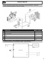
INSTALLATION – FONCTIONNEMENT PRODUIT
Seul le personnel expérimenté et habilité par le fabricant peut effectuer l’installation. Pendant l’installation, s’assurer que
le générateur est déconnecté du réseau. Les connexions en série ou en parallèle de générateur sont interdites. Il est
recommandé d’utiliser les câbles de soudage fournis avec l’appareil an d’obtenir les réglages optimum
du produit.
DESCRIPTION DES MATÉRIELS
Ces postes de soudure Inverter, portables, ventilés, sont conçus pour le soudage à l’électrode enrobée (MMA) et à
électrode réfractaire (TIG Lift) en courant continu (DC). En MMA, ils soudent tout type d’électrode : rutile, inox, fonte,
basique. En Tig, ils soudent la plupart des métaux sauf l’aluminum et ses alliages. Ils sont protégés pour le fonctionne-
ment sur groupes électrogènes (Alim 230 V AC).
ALIMENTATION-MISE EN MARCHE
Ce matériel est livre avec une prise 16 A de type CEE7/7 et ne doit être utilisé que sur une installation électrique mono-
phasée 230 V (50 - 60 Hz) à trois ls avec un neutre relié à la terre.
Le courant effectif absorbé (I1eff) est indiqué sur l’appareil, pour les conditions d’utilisation maximales. Vérier que
l’alimentation et ses protections (fusible et/ou disjoncteur) sont compatibles avec le courant nécessaire en utilisation.
Dans certains pays, il peut être nécessaire. de changer la prise pour permettre une utilisation aux conditions maximales.
• La mise en marche s’effectue par une pression sur la touche «
».
• L’appareil se met en protection si la tension d’alimentation est supérieure à 265V pour les postes monophasés (l’af-
cheur indique ).
Le fonctionnement normal reprend dès que la tension d’alimentation revient dans sa plage nominale.
BRANCHEMENT SUR GROUPE ÉLECTROGÈNE
Ce matériel peut fonctionner avec des groupes électrogènes à condition que la puissance auxiliaire réponde aux exi-
gences suivantes :
- La tension doit être alternative, réglée comme spéciée et de tension crête inférieure à 400 V ;
- La fréquence doit être comprise entre 50 et 60 Hz.
Il est impératif de vérier ces conditions, car de nombreux groupes électrogènes produisent des pics de haute tension
pouvant endommager le matériel.
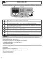
SOUDAGE À L’ÉLECTRODE ENROBÉE (MODE MMA)
BRANCHEMENT ET CONSEILS
• Brancher les câbles; porte-électrode et pince de masse dans les connecteurs de raccordement,
• Respecter les polarités et intensités de soudage indiquées sur les boîtes d’électrodes,
• Enlever l’électrode du porte-électrode lorsque le matériel n’est pas utilisé.
• Les appareils sont munis de 3 fonctionnalités spéciques aux Inverters :
- Le Hot Start procure une surintensité en début de soudage.
- L’Arc Force délivre une surintensité qui évite le collage lorsque l’électrode rentre dans le bain.
- L’Anti-Sticking permet de décoller facilement l’électrode sans la faire rougir en cas de collage.
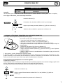
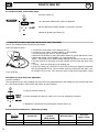
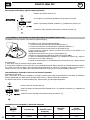
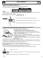
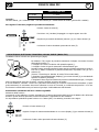
Activation du mode MMA et réglage de l’intensité :
- Sélectionner la position MMA (2) avec le sélecteur (5)
(Presser 3 secondes pour basculer du mode TIG au mode MMA)
- Régler l’intensité souhaitée (afcheur(1)) grâce aux touches (4).
FR

7
PROGYS 200A PFC
MADE IN FRANCE
FR
PROGYS 200A PFC
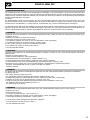
HOT START 0 > 90%
ARC FORCE Automatique
Conseils :
Hot start faible, pour les tôles nes et Hot start élevé pour les métaux difciles à souder (pièces sales ou oxydées)
Pour régler le Hot Start, suivre les étapes suivantes :
OK
OK
0 - 90 %
Presser le sélecteur (5).
L’inscription «H» (Hot Start) s’afche suivi d’un pourcentage.
Régler le pourcentage souhaité (afcheur (1)) grâce aux touches (4).
Valider la valeur souhaitée en pressant sur le sélecteur (5).
SOUDAGE A L’ÉLECTRODE TUNGSTENE SOUS GAZ INERTE (MODE TIG)
Le soudage TIG DC requiert une protection gazeuse (Argon).
Pour souder en TIG, suivre les étapes suivantes :
1. Connecter la pince de masse sur la polarité positive (+).
2. Brancher une torche « à valve » sur la polarité négative (-).
3. Raccorder le tuyau de gaz au manodétendeur de la bouteille de gaz.
Il sera parfois nécessaire de le couper avant l’écrou si ce dernier n’est pas adapté au
manodétendeur
4. Sélectionner la position TIG (3) avec le sélecteur (5).
(Presser 3 secondes pour basculer du mode TIG au mode MMA)
5. Régler l’intensité souhaitée (afcheur(1)) grâce aux touches (4), selon l’épaisseur
à souder (30A/mm).
6. Régler le débit de gaz sur le manodétendeur de la bouteille de gaz, puis ouvrir la
valve de la torche
7. Pour amorcer : toucher l’électrode sur la pièce à souder.
8. En n de soudure : lever 2 fois l’arc (haut-bas-haut-bas) pour déclencher l’évanouissement automatique (cf para-
graphe ci-dessous). Ce mouvement doit être effectué en moins de 4 secondes, sur une hauteur de 5 à 10 mm. Puis
fermer la valve de la torche pour arrêter le gaz après refroidissement de l’électrode
Évanouissement automatique de l’arc à durée réglable
Activation de la fonction :
Cela correspond en n de soudure au temps nécessaire pour la baisse progressive du courant de soudage jusqu’à l’arrêt
de l’arc. Cette fonction permet d’éviter les ssures et les cratères de n de soudure.
Par défaut cette fonction n’est pas activée (OFF). Pour l’activer, procéder comme suit :
(OFF)
OK
Presser sur le sélecteur (5).
Régler le temps d’évanouissement souhaité de 1 à 10 sec (afcheur (1)) grâce aux
touches (4).
Valider la valeur souhaitée en pressant sur le sélecteur (5).

8
PROGYS 200A PFC
MADE IN FRANCE
FR
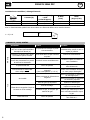
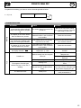
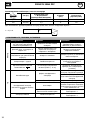
Combinaisons conseillées / affutage électrode
Courant (A)
Ø Electrode (mm)
= Ø l
(métal d’apport)
Ø Buse
(mm)
Débit
(Argon l/mn)
0,5-5 10-130 1,6 9,8 6-7
4-8 130-200 2,4 11 7-8
Pour un fonctionnement optimal vous devez utiliser une électrode affûtée de la manière suivante :
L = 2,5 x d.
L
d
ANOMALIE, CAUSE, REMÈDE
Anomalies Causes Remèdes
MMA-TIG
L’appareil ne délivre pas de cou-
rant et le voyant jaune de défaut
thermique est allumé (6).
La protection thermique du poste
s’est enclenchée.
Attendre la n de la période de
refroidissement, environ 2 min. Le
voyant (6) s’éteint.
L’afcheur est allumé mais l’appa-
reil ne délivre pas de courant.
Le câble de pince de masse ou
porte électrode n’est pas connecté
au poste.
Vérier les branchements.
Le poste est alimenté, vous res-
sentez des picotements en posant
la main sur la carrosserie.
La mise à la terre est défectueuse.
Contrôler la prise et la terre de
votre installation.
Le poste soude mal Erreur de polarité
Vérier la polarité conseillée sur la
boîte d'électrode.
Lors de la mise en route, l’af-
cheur indique
.
La tension d’alimentation n’est pas
respectée
(230 V monophasée +/- 15 %)
Vérier votre installation électrique
ou votre groupe électrogène
TIG
Arc instable
Défaut provenant de l'électrode en
tungstène
Utiliser une électrode en tungstène
de taille appropriée
Utiliser une électrode en tungstène
correctement préparée
Débit de gaz trop important Réduire le débit de gaz
L’électrode en tungstène s’oxyde et
se ternit en n de soudage
Zone de soudage.
Protéger la zone de soudage
contre les courants d'air.
Problème de gaz, ou coupure pré-
maturée du gaz
Contrôler et serrer tous les rac-
cords de gaz. Attendre que l'élec-
trode refroidisse avant de couper
le gaz.
L'électrode fond Erreur de polarité
Vérier que la pince de masse est
bien reliée au +

9
PROGYS 200A PFC
MADE IN FRANCE
EN
WARNING - SAFETY RULES
GENERAL INSTRUCTIONS
Read and understand the following safety recommendations before using or servicing the unit.
Any change or servicing that is not specied in the instruction manual must not be undertaken.
The manufacturer is not liable for any injury or damage caused due to non-compliance with the instructions featured
in this manual .
In the event of problems or uncertainties, please consult a qualied person to handle the installation properly.
ENVIRONMENT
This equipment must only be used for welding operations in accordance with the limits indicated on the descriptive panel
and/or in the user manual. The operator must respect the safety precautions that apply to this type of welding. In case
of inedaquate or unsafe use, the manufacturer cannot be held liable for damage or injury.
This equipment must be used and stored in a place protected from dust, acid or any other corrosive agent. Operate the
machine in an open, or well-ventilated area.
Operating temperature:
Use between -10 and +40°C (+14 and +104°F).
Store between -20 and +55°C (-4 and 131°F).
Air humidity:
Lower or equal to 50% at 40°C (104°F).
Lower or equal to 90% at 20°C (68°F).
Altitude:
Up to 1000 meters above sea level (3280 feet).
INDIVIDUAL PROTECTIONS AND OTHERS
Arc welding can be dangerous and can cause serious and even fatal injuries.
Welding exposes the user to dangerous heat, arc rays, electromagnetic elds, noise, gas fumes, and electrical shocks.
People wearing pacemakers are advised to consult with their doctor before using this device.
To protect oneself as well as the other, ensure the following safety precautions are taken:
In order to protect you from burns and radiations, wear clothing without cuffs. These clothes must be
insulated, dry, reproof and in good condition, and cover the whole body.
Wear protective gloves which guarantee electrical and thermal insulation.
Use sufcient welding protective gear for the whole body: hood, gloves, jacket, trousers... (varies depen-
ding on the application/operation). Protect the eyes during cleaning operations. Do not operate whilst
wearing contact lenses.
It may be necessary to install reproof welding curtains to protect the area against arc rays, weld spatters
and sparks.
Inform the people around the working area to never look at the arc nor the molten metal, and to wear
protective clothes.
Ensure ear protection is worn by the operator if the work exceeds the authorised noise limit (the same
applies to any person in the welding area).
Stay away from moving parts (e.g. engine, fan...) with hands, hair, clothes etc...
Never remove the safety covers from the cooling unit when the machine is plugged in - The manufac-
turer is not responsible for any accident or injury that happens as a result of not following these safety
precautions.
The pieces that have just been welded are hot and may cause burns when manipulated. During mainte-
nance work on the torch or the electrode holder, you should make sure it’s cold enough and wait at least
10 minutes before any intervention. The cooling unit must be on when using a water cooled torch in order
to ensure that the liquid does not cause any burns.
ALWAYS ensure the working area is left as safe and secure as possible to prevent damage or accidents.

10
PROGYS 200A PFC
MADE IN FRANCE
EN
WELDING FUMES AND GAS
The fumes, gases and dust produced during welding are hazardous. It is mandatory to ensure adequate
ventilation and/or extraction to keep fumes and gases away from the work area. An air fed helmet is
recommended in cases of insufcient air supply in the workplace.
Check that the air intake is in compliance with safety standards.
Care must be taken when welding in small areas, and the operator will need supervision from a safe distance. Welding
certain pieces of metal containing lead, cadmium, zinc, mercury or beryllium can be extremely toxic. The user will also
need to degrease the workpiece before welding.
Gas cylinders must be stored in an open or ventilated area. The cylinders must be in a vertical position secured to a
support or trolley.
Do not weld in areas where grease or paint are stored.
FIRE AND EXPLOSIONS RISKS
Protect the entire welding area. Compressed gas containers and other inammable material must be
moved to a minimum safe distance of 11 meters.
A re extinguisher must be readily available.
Be careful of spatter and sparks, even through cracks. It can be the source of a re or an explosion.
Keep people, ammable objects and containers under pressure at a safe distance.
Welding of sealed containers or closed pipes should not be undertaken, and if opened, the operator must remove any
inammable or explosive materials (oil, petrol, gas...).
Grinding operations should not be directed towards the device itself, the power supply or any ammable materials.
GAS BOTTLE
Gas leaking from the cylinder can lead to suffocation if present in high concentrations around the work
area.
Transport must be done safely: Cylinders closed and product off. Always keep cylinders in an upright
position securely chained to a xed support or trolley.
Close the bottle after any welding operation. Be wary of temperature changes or exposure to sunlight.
Cylinders should be located away from areas where they may be struck or subjected to physical damage.
Always keep gas bottles at a safe distance from arc welding or cutting operations, and any source of
heat, sparks or ames.
Be careful when opening the valve on the gas bottle, it is necessary to remove the tip of the valve and
make sure the gas meets your welding requirements.
ELECTRIC SAFETY
The machine must be connected to an earthed electrical supply. Use the recommended fuse size.
An electrical discharge can directly or indirectly cause serious or deadly accidents .
Do not touch any live part of the machine (inside or outside) when it is plugged in (Torches, earth cable, cables,
electrodes) because they are connected to the welding circuit.
Before opening the device, it is imperative to disconnect it from the mains and wait 2 minutes, so that all the capacitors
are discharged.
Do not touch the torch or electrode holder and earth clamp at the same time.
Damaged cables and torches must be changed by a qualied and skilled professional. Make sure that the cable cross
section is adequate with the usage (extensions and welding cables). Always wear dry clothes in good condition, in order
to be insulated from the electrical circuit. Wear insulating shoes, regardless of the environment in which you work in.
EMC CLASSIFICATION
These Class A devices are not intended to be used on a residential site where the electric current is
supplied by the public network, with a low voltage power supply. There may be potential difculties in
ensuring electromagnetic compatibility on these sites, because of the interferences, as well as radio
frequencies.

11
PROGYS 200A PFC
MADE IN FRANCE
EN
This equipment complies with the IEC 61000-3-12 standard.
This equipment complies with IEC 61000-3-11 if the power supply network’s impedance at the
electrical installation’s connection point is inferior to the network’s maximum admissible impendance
Zmax = 0.281 Ohms.
ELECTROMAGNETIC INTERFERENCES
The electric currents owing through a conductor cause electrical and magnetic elds (EMF). The
welding current generates an EMF eld around the welding circuit and the welding equipment.
The EMF elds may disrupt some medical implants, such as pacemakers. Protection measures should be taken for
people wearing medical implants. For example, access restrictions for passers-by or an individual risk evaluation for the
welders.
All welders should take the following precautions in order to minimise exposure to the electromagnetic elds (EMF)
generated by the welding circuit::
• position the welding cables together – if possible, attach them;
• keep your head and torso as far as possible from the welding circuit;
• never enroll the cables around your body;
• never position your body between the welding cables. Hold both welding cables on the same side of your body;
• connect the earth clamp as close as possible to the area being welded;
• do not work too close to, do not lean and do not sit on the welding machine
• do not weld when you’re carrying the welding machine or its wire feeder.
People wearing pacemakers are advised to consult their doctor before using this device.
Exposure to electromagnetic elds while welding may have other health effects which are not yet
known.
RECOMMENDATIONS TO ASSESS THE WELDING AREA AND WELDING INSTALLATION
Overview
The user is responsible for installing and using the arc welding equipment in accordance with the manufacturer’s
instructions. If electromagnetic disturbances are detected, it is the responsibility of the user of the arc welding equipment
to resolve the situation with the manufacturer’s technical assistance. In some cases, this remedial action may be as
simple as earthing the welding circuit. In other cases, it may be necessary to construct an electromagnetic shield around
the welding power source and around the entire piece by tting input lters. In all cases, electromagnetic interferences
must be reduced until they are no longer bothersome.
Welding area assessment
Before installing the machine, the user must evaluate the possible electromagnetic problems that may arise in the area
where the installation is planned.
. In particular, it should consider the following:
a) the presence of other power cables (power supply cables, telephone cables, command cable, etc...)above, below and
on the sides of the arc welding machine.
b) television transmitters and receivers ;
c) computers and other hardware;
d) critical safety equipment such as industrial machine protections;
e) the health and safety of the people in the area such as people with pacemakers or hearing aids;
f) calibration and measuring equipment
g)The isolation of the equipment from other machinery.
The user will have to make sure that the devices and equipments that are in the same room are compatible with each
other. This may require extra precautions;
h) make sure of the exact hour when the welding and/or other operations will take place.
The surface of the area to be considered around the device depends on the the building’s structure and other activities
that take place there. The area taken in consideration can be larger than the limits determined by the companies.
Welding area assessment
Besides the welding area, the assessment of the arc welding systems intallation itself can be used to identify and resolve
cases of disturbances. The assessment of emissions must include in situ measurements as specied in Article 10 of
CISPR 11: 2009. In situ measurements can also be used to conrm the effectiveness of mitigation measures.

12
PROGYS 200A PFC
MADE IN FRANCE
EN
RECOMMENDATION ON METHODS OF ELECTROMAGNETIC EMISSIONS REDUCTION
a. National power grid: The arc welding machine must be connected to the national power grid in accordance with
the manufacturer’s recommendation. If interferences occur, it may be necessary to take additional preventive measures
such as the ltering of the power suplly network. Consideration should be given to shielding the power supply cable in a
metal conduit. It is necessary to ensure the shielding’s electrical continuity along the cable’s entire length. The shielding
should be connected to the welding current’s source to ensure good electrical contact between the conduct and the
casing of the welding current source.
b. Maintenance of the arc welding equipment: The arc welding machine should be be submitted to a routine
maintenance check according to the manufacturer’s recommendations. All accesses, service doors and covers should be
closed and properly locked when the arc welding equipment is on.. The arc welding equipment must not be modied
in any way, except for the changes and settings outlined in the manufacturer’s instructions. The spark gap of the arc
start and arc stabilization devices must be adjusted and maintained according to the manufacturer’s recommendations.
c. Welding cables: Cables must be as short as possible, close to each other and close to the ground, if not on the
ground.
d. Electrical bonding : consideration shoud be given to bonding all metal objects in the surrounding area. However,
metal objects connected to the workpiece increase the riskof electric shock if the operator touches both these metal
elements and the electrode. It is necessary to insulate the operator from such metal objects.
e. Earthing of the welded part : When the part is not earthed - due to electrical safety reasons or because of its size
and its location (which is the case with ship hulls or metallic building structures), the earthing of the part can, in some
cases but not systematically, reduce emissions It is preferable to avoid the earthing of parts that could increase the risk
of injury to the users or damage other electrical equipment. If necessary, it is appropriate that the earthing of the part
is done directly, but in some countries that do not allow such a direct connection, it is appropriate that the connection
is made with a capacitor selected according to national regulations.
f. Protection and plating : The selective protection and plating of other cables and devices in the area can reduce
perturbation issues. The protection of the entire welding area can be considered for specic situations.
TRANSPORT AND TRANSIT OF THE WELDING MACHINE
The machine is tted with handle(s) to facilitate transportation. Be careful not to underestimate the
machine’s weight. The handle(s) cannot be used for slinging.
Do not use the cables or torch to move the machine. The welding equipment must be moved in an
upright position.
Do not place/carry the unit over people or objects.
Never lift the machine while there is a gas cylinder on the support shelf. A clear path is available when
moving the item.
EQUIPMENT INSTALLATION
• Put the machine on the oor (maximum incline of 10°.)
• Ensure the work area has sufcient ventillation for welding, and that there is easy access to the control panel.
• The machine must not be used in an area with conductive metal dusts.
• The machine must be placed in a sheltered area away from rain or direct sunlight.
• The machine protection level is IP21, which means :
- Protection against acess to dangerous parts from solid bodies of a ≥12.5mm diameter and,
- Protection against vertically falling drops.
The manufacturer does not incur any responsability regarding damages to both objects and persons
that result from an incorrect and/or dangerous use of the machine.
MAINTENANCE / RECOMMENDATIONS
• Maintenance should only be carried out by a qualied person. Annual maintenance is recommended.
• Ensure the machine is unplugged from the mains, and wait for two minutes before carrying out main-
tenance work. DANGER High Voltage and Currents inside the machine.
• Remove the casing 2 or 3 times a year to remove any excess dust. Take this opportunity to have the
electrical connections checked by a qualied person, with an insulated tool.
• Regularly check the condition of the power supply cable. If the power cable is damaged, it must be
replaced by the manufacturer, its after sales service or an equally qualied person.
• Ensure the ventilation holes of the device are not blocked to allow adequate air circulation.
• Do not use this equipment to thaw pipes, to charge batteries, or to start any engine.

13
PROGYS 200A PFC
MADE IN FRANCE
EN
INSTALLATION – PRODUCT OPERATION
Only qualied personnel authorized by the manufacturer should perform the installation of the welding equipment.
During set up, the operator must ensure that the machine is unplugged. Connecting generators in a series or a parallel
circuit is forbidden. It is recommended to use the welding cables supplied with the unit in order to obtain
the optimum product settings.
HARDWARE DESCRIPTION
These welding are, Inverter, portable welder, for covered electrode and TIG Lift in DC. It allows welding with rutiles,
basic, stainless steel. In TIG, it allows to weld most of metals except aluminium and alloys. It is protected for a use on
electric generators (Alim 230 V AC).
POWER SUPPLY – START UP
This machine is tted with a 16A socket type CEE7/7 which must be connected to a single-phase 230V (50 - 60 Hz)
power supply tted with three wires and one earthed neutral.
The absorbed effective current (I1eff) is displayed on the machine, for optimal use. Check that the power supply and
its protection (fuse and/or circuit breaker) are compatible with the current needed by the machine. In some countries,
it may be necessary to change the plug to allow the use at maximum settings.
• The start-up is done by pressing «
»
The device turns into protection mode if the supply voltage is over 265V for the single-phase products (the sсreen dis-
plays
).
Normal operation will resume when the voltage has returned to its nominal range.
CONNECTION ON A GENERATOR
The machine can work with generators as long as the auxiliary power matches these requirements :
- The voltage must be AC, always set as specied, and the peak voltage below 400V,
- The frequency must be between 50 and 60 Hz.
It is imperative to check these requirements as several generators generate high voltage peaks that can damage these
machines.
MMA WELDING (ELECTRODE)
CONNECTION AND ADVICE
• Leave the machine connected to the supply after welding in order to let it cool down.
• Thermal protection: thermal protection indicator turns on and the cooling time is about 2 to 5 min according to exter-
nal temperature.
• Your machine is equipped with 3 specic functions to Inverters :
- The Hot Start increases the current at the beginning of the welding.
- The Arc Force increases the current in order to avoid the sticking when electrode enters in melted metal.
- The Anti Sticking allows you to easily withdraw your electrode without damaging it in case of sticking.
Selection of MMA Mode and intensity setting:
- Select the MMA position (2) with the selector (5).
(Press 3 seconds to switch from TIG to MMA)
- Adjust the wished current (display (1)) using the key (4).
PROGYS 200A PFC
HOT START 0 > 90%
ARC FORCE Automatic
Advice: :
Low Hot Start: for thin metal sheets
High Hot Start for metals that are difcult to weld (dirty or oxidized parts)

14
PROGYS 200A PFC
MADE IN FRANCE
EN
To set the Hot Start, follow these steps :
OK
OK
0 - 90 %
Press the switch (5).
«H» (Hot Start) blinks and a number is displayed.
Set the desired percentage (display (1)) using the (4) keys.
Validate by pressing the switch (5).
TUNGSTEN ELECTRODE WELDING WITH INERT GAS (TIG MODE)
The DC TIG welding requires a protective gas (argon)
Follow the steps as below :
1. Connect the earth clamp on the positive pole (+).
2. Connect a torch «valve» negative polarity (-).(Ref. 044425)
3. Connect the pipe gas torch on the gas cylinder
4. Select the TIG position (3) using the selector button (5) (press and hold for 3 sec).
5. Adjust the wished current (display (1)) using the keys (4).
Advice : Take 30A/mm as a default setting and adjust according to the part to weld.
6. Set the gas ow on ewmeter of the gas cylinder, and then open the valve of the
torch.
7. To boot : Touch the electrode on the welding part
8. At end of welding: Up 2 times the arc (up-down-up-down) to trigger the automatic
fade (see paragraph below). This movement must be performed in less than 4 sec,
at a height of 5 to 10 mm. Then close the valve to stop the torch gas after cooling
of the electrode.
Automatic Arc slope with time adjustable
Function activation:
This corresponds to the end of welding time required for the gradual decline in the welding current until the stop of the
arc. This function helps to avoid cracks and craters at end of welding.
(OFF)
OK
1. Press the selector switch (5)
2. Set the automatic arc slope you wish from 1 to 10 sec (display(1)) using key
3. Validate the required gure by pressing the selector button (5).
Recommended combinations / Electrode grinding
Current (A)
Ø Electrode (mm)
= Ø wire
(ller metal)
Ø Nozzle (mm)
Flow rate
(Argon L/mn)
0,5-5 10-130 1,6 9,8 6-7
4-8 130-200 2,4 11 7-8

15
PROGYS 200A PFC
MADE IN FRANCE
EN
To optimize the working, you have to use an electrode grinded as below:
L = 2,5 x d.
L
d
TROUBLESHOOTING
Anomalies Causes Remedies
MMA-TIG
The device does not deliver any
current and the yellow indicator
lamp of thermal defect (6) lights
up.
The welder thermal protection has
turned on.
Wait for the end of the cooling
time, around 2 minutes. The indi-
cator lamp (7) turns off.
The display is on but the device
does not deliver any current.
The cable of the earth clamp or
electrode holder is not connected
to the welder.
Check the connections.
If, when the unit is on and you put
your hand on the welding unit’s
body, you feel tingling sensation.
The welding unit is not correctly
connected to the earth.
Check the plug and the earth of
your electrical network.
The display is on but the device
does not deliver any current.
The cable of the earth clamp or
electrode holder is not connected
to the welder.
Check the connections.
When starting up,
the display indicates
.
The voltage is not included in the
range 230V +/- 15%
Have the electrical installation
checked.
TIG
Instable arc
Default coming from the tungsten
electrode
Use a tungsten electrode with the
adequate size
Use a well prepared tungsten
electrode
Too important gas ow rate Reduce gas ow rate
The tungsten electrode gets
oxidised and tern at the end of
welding.
Welding zone
Protect welding zone against air
ows
Default coming from post-gas or
the gas has been stopped prema-
turely.
Check and tighten all gas connec-
tions. Wait until the electrode cools
down before stopping the gas.
The electrode melts Polarity error
Check that the earth clamp is
really connected to +

16
PROGYS 200A PFC
MADE IN FRANCE
DE
SICHERHEITSANWEISUNGEN
ALLGEMEIN
Die Missachtung dieser Anweisungen und Hinweise kann zu schweren Personen- und Sachschäden
führen.
Nehmen Sie keine Wartungarbeiten oder Veränderungen am Gerät vor, die nicht explizit in der Anlei-
tung gennant werden.
Der Hersteller haftet nicht für Verletzungen oder Schäden, die durch unsachgemäße Handhabung dieses Gerätes ens-
tanden sind.
Bei Problemen oder Fragen zum korrekten Gebrauch dieses Gerätes, wenden Sie sich bitte an entsprechend quali-
ziertes und geschultes Fachpersonal.
UMGEBUNG
Dieses Gerät darf ausschließlich für Schweißarbeiten für die auf dem Siebdruck-Aufdruck bzw. dieser Anleitung ange-
gebenen Materialanforderungen (Material, Materialstärke, usw) verwendet werden. Es wurde allein für die sachgemäße
Anwendung in Übereinstimmung mit konventionellen Handelspraktiken und Sicherheitsvorschriften konzipiert. Der Hers-
teller ist nicht für Schäden bei fehlerhaften oder gefährlichen Verwendung nicht verantwortlich.
Verwenden Sie das Gerät nicht in Räumen, in denen sich in der Luft metallische Staubpartikel benden, die Elektrizität
leiten können. Achten Sie sowohl beim Betrieb als auch bei der Lagerung des Gerätes auf eine Umgebung, die frei von
Säuren, Gasen und anderen ätzenden Substanzen ist. Achten Sie auf eine gute Belüftung und ausreichenden Schutz
bzw. Ausstattung der Räumlichkeiten.
Betriebstemperatur:
zwischen -10 und +40°C (+14 und +104°F).
Lagertemperatur zwischen -20 und +55°C (-4 und 131°F).
Luftfeuchtigkeit:
Niedriger oder gleich 50% bis 40°C (104°F).
Niedriger oder gleich 90% bis 20°C (68°F).
Das Gerät ist bis in einer Höhe von 2.000m (über NN) einsetzbar.
SICHERHEITSHINWEISE
Lichtbogenschweißen kann gefährlich sein und zu schweren - unter Umständen auch tödlichen - Verletzungen führen.
Beim Lichtbogen ist der Anwender einer Vielzahl potentieller Risiken ausgesetzt: gefährliche Hitzequelle, Lichtbogens-
trahlung, elektromagnetische Störungen (Personen mit Herzschnittmacher oder Hörgerät sollten sich vor Arbeiten in der
Nähe der Maschinen von einem Arzt beraten lassen), elektrische Schläge, Schweißlärm und -rauch.
Schützen Sie daher sich selbst und andere. Beachten Sie unbedingt die folgenden Sicherheitshinweise:
Die Strahlung des Lichtbogens kann zu schweren Augenschäden und Hautverbrennungen führen. Die
Haut muss durch geeignete, trockene Schutzbekleidung (Schweißerhandschuhe, Lederschürze, Si-
cherheitsschuhe) geschützt werden.
Tragen Sie bitte elektrisch- und wärmeisolierende Schutzhandschuhe.
Tragen Sie bitte Schweißschutzkleidung und einen Schweißschutzhelm mit einer ausreichenden
Schutzstufe (je nach Schweißart und -strom). Schützen Sie Ihre Augen bei Reinigungsarbeiten. Kontakt-
linsen sind ausdrücklich verboten!
Schirmen Sie den Schweißbereich bei enstprechenden Umgebungsbedingungen durch Schweißvorhänge
ab, um Dritte vor Lichtbogenstrahlung, Schweißspritzern, usw. zu schützen.
In der Nähe des Lichtbogens bendliche Personen müssen ebenfalls auf Gefahren hingewiesen werden
und mit den nötigen Schutz ausgerüstet werden.
Bei Gebrauch des Schweißgerätes ensteht sehr großer Lärm, der auf Dauer das Gehör schädigt. Tragen
Sie daher im Dauereinsatz ausreichend Gehörschutz und schützen Sie in der Nähe arbeitende Personen.
Achten Sie auf einen ausreichenden Abstand mit ungeschützten Hände, Haaren und Kleidungstücken
zum Lüfter.
Entfernen Sie unter keinen Umständen das Gerätegehäuse, wenn dieses am Stromnetz angeschlossen
ist. Der Hersteller haftet nicht für Verletzungen oder Schäden, die durch unsachgemäße Handhabung
dieses Gerätes bzw. Nichteinhaltung der Sicherheitshinweise entstanden sind.

17
PROGYS 200A PFC
MADE IN FRANCE
DE
ACHTUNG! Das Werkstück ist nach dem Schweißen sehr heiß! Seien Sie daher im Umgang mit dem
Werkstück vorsichtig, um Verbrennungen zu vermeiden. Achten Sie vor Instandhaltung / Reinigung eines
wassergekühlten Brenners darauf, dass Kühlaggregat nach Schweißende ca. 10min weiterlaufen zu las-
sen, damit die Kühlüssigkeit entsprechend abkühlt und Verbrennungen vermieden werden.
Der Arbeitsbereich muss zum Schutz von Personen und Geräten vor dem Verlassen gesichert werden.
SCHWEISSRAUCH/-GAS
Beim Schweißen entstehen Rauchgase bzw. toxische Dämpfe, die zu Sauerstoffmangel in der Atemluft
führen können. Sorgen Sie daher immer für ausreichend Frischluft, technische Belüftung (oder ein
zugelassenes Atmungsgerät).
Verwenden Sie die Schweßanlagen nur in gut belüfteten Hallen, im Freien oder in geschlossenen Räu-
men mit einer den aktuellen Sicherheitsstandards entsprechender Absaugung.
Achtung! Bei Schweißarbeiten in kleinen Räumen müssen Sicherheitsabstände besonders beachtet werden. Beim
Schweißen von Blei, auch in Form von Überzügen, verzinkten Teilen, Kadmium, «kadmierte Schrauben», Beryllium
(meist als Legierungsbestandteil, z.B. Beryllium-Kupfer) und andere Metalle entstehen giftige Dämpfe. Erhöhte Vorsicht
gilt beim Schweißen von Behältern. Entleeren und reinigen Sie diese zuvor. Um die Bildung von Giftgasen zu vermeiden
bzw. zu verhindern, muss der Schweißbereich des Werkstückes von Lösungs- und Entfettungsmitteln gereinigt werden.
Die zum Schweißen benötigten Gasaschen müssen in gut belüfteter, gesicherter Umgebung aufbewahrt werden. Lagern
Sie sie ausschließlich in vertikaler Position und sichern Sie sie z.B. mithilfe eines entsprechenden Gasaschenfahrwagens
gegen Umkippen. Informationen zum richtigen Umgang mit Gasaschen erhalten Sie von Ihrem Gaselieferanten.
Schweißarbeiten in unmittelbarer Nähe von Fett und Farben sind grundsätzlich verboten!
BRAND- UND EXPLOSIONSGEFAHR
Sorgen Sie für ausreichenden Schutz des Schweißbereiches. Der Sicherheitsabstand für Gasaschen
(brennbare Gase) und andere brennbare Materialien beträgt mindestens 11 Meter.
Brandschutzausrüstung muss am Schweißbplatz vorhanden sein.
Beachten Sie die beim Schweißen entstehende heiße Schlacke, Spritzer und Funken. Sie sind eine potentielle
Entstehungsquelle für Feuer oder Explosionen.
Behalten Sie einen Sicherheitsabstand zu Personen, entammbaren Gegenständen und Druckbehältern.
Schweißen Sie keine Behälter, die brennbare Materialien enthalten (auch keine Reste davon) -> Gefahr entammbarer
Gase). Bei geöffneten Behältern müssen vorhandene Reste entammbarer oder explosiver Stoffe entfernt werden.
Arbeiten Sie bei Schleifarbeiten immer in entgegengesetzer Richtung zu diesem Gerät und entammbaren Materialen.
GASDRUCKAUSRÜSTUNG
Austretendes Gas kann in hoher Konzentration zum Erstickungstod führen. Sorgen Sie daher immer für
eine gut belüftete Arbeits- und Lagerumgebung.
Achten Sie darauf, dass die Gasaschen beim Transport verschlossen sind und das Schweißgerät
ausgeschaltet ist. Lagern Sie die Gasaschen ausschließlich in vertikaler Position und sichern Sie sie z.B.
mithilfe eines entsprechenden Gasaschenfahrwagens gegen Umkippen.
Verschließen Sie die Flaschen nach jedem Schweißvorgang. Schützen Sie sie vor direkter
Sonneneinstrahlung, offenem Feuer und starken Temperaturschwankungen (z.B. sehr tiefen
Temperaturen).
Positionieren Sie die Gasaschen stets mit ausreichendem Abstand zu Schweiß- und Schleifarbeiten
bzw. jeder Hitze-, Funken- und Flammenquelle.
Halten Sie mit den Gasaschen Abstand zu Hochspannung und Schweißarbeiten. Das Schweißen einer
Druckglasasche ist untersagt.
Bei Erstöffnung des Gasventils muss der Plastikverschluss/Garantiesiegel von der Flasche entfernt
werden. Verwenden Sie ausschließlich Gas, das für die Schweißarbeit mit den von Ihnen ausgewählten
Materialen geeignet ist.
ELEKTRISCHE SICHERHEIT
Das Schweißgerät darf ausschließlich an einer geerdeten Netzversorgung betrieben werden. Verwenden
Sie nur die empfohlenen Sicherungen.
Das Berühren stromführender Teile kann tödliche elektrische Schläge, schwere Verbrennungen bis zum
Tod verursachen.

18
PROGYS 200A PFC
MADE IN FRANCE
DE
Berühren Sie daher UNTER KEINEN UMSTÄNDEN Teile des Geräteinneren oder das geöffnete Gehäuse, wenn das Gerät
im Betrieb ist..
Trennen Sie das Gerät IMMER vom Stromnetz und warten Sie zwei weitere Minuten BEVOR Sie das Gerät öffnen, damit
sich die Spannung der Kondensatoren entladen kann.
Berühren Sie niemals gleichzeitig Brenner und Masseklemme!
Der Austausch von beschädigten Kabeln oder Brennern darf nur von qualiziertem und geschultem Fachpersonal
vorgenommen werden. Tragen Sie beim Schweißen immer trockene, unbeschädigte Kleidung. Tragen Sie unabhängig
von den Umgebungsbedingungen immer isolierendes Schuhwerk.
CEM-KLASSE DES GERÄTES
ACHTUNG! Dieses Gerät wird als Klasse A Gerät eingestuft. Es ist nicht für den Einsatz in Wohngebie-
ten bestimmt, in denen die lokale Energieversorgung über das öffentliche Niederspannungsnetz gere-
gelt wird. In diesem Umfeld ist es auf Grund von Hochfrequenz-Störungen und Strahlungen schwierig
die elektromagnetische Verträglichkeit zu gewährleisten.
Das Gerät entspricht der Norm IEC 61000-3-12.
Dieses Gerät ist dann mit der Norm IEC 61000-3-11 konform, wenn die Netzimpedanz an
der Übergabestelle zum Versorgungsnetz niedriger als die maximale zulässige Netzimpedanz
Zmax = 0.281 Ohm ist.
ELEKTROMAGNETISCHE FELDER UND STÖRUNGEN
Der durch Leiter ießende elektrische Strom erzeugt lokale elektrische und magnetische Felder (EMF).
Beim Betrieb von Lichtbogenschweißanlagen kann es zu elektromagnetischen Störungen kommen.
Durch den Betrieb dieses Gerätes können elektromedizinische, informationstechnische und andere Geräte in ihrer
Funktionsweise beeinträchtigt werden. Personen, die Herzschrittmacher oder Hörgeräte tragen, sollten sich vor Arbeiten
in der Nähe der Maschine, von einem Arzt beraten lassen. Zum Beispiel Zugangseinschränkungen für Passanten oder
individuelle Risikobewertung für Schweißer.
Alle Schweißer sollten gemäß dem folgenden Verfahren die Exposition zu elektromagnetischen Feldern aus
Lichtbogenschweißgeräten minimieren :
• Elektrodenhalter und Massekabel bündeln, wenn möglich machen Sie sie mit Klebeband fest;
• Achten Sie darauf, dass ihren Oberkörper und Kopf sich so weit wie möglich von der Schweißarbeit entfernt benden;
• Achten Sie darauf, dass sich die Kabel, der Brenner oder die Masseklemme nicht um Ihren Körper wickeln;
• Stehen Sie niemals zwischen Masse- und Brennerkabel. Die Kabel sollten stets auf einer Seite liegen;
• Verbinden Sie die Massezange mit dem Werkstück möglichst nahe der Schweißzone;
• Arbeiten Sie nicht unmittelbar neben der Schweißstromquelle;
• Während des Transportes der Stromquelle oder des Drahtvorschubkoffer nicht schweißen.
Personen, die Herzschrittmacher oder Hörgeräte tragen, sollten sich vor Arbeiten in der Nähe der
Maschine, von einem Arzt beraten lassen.
Durch den Betrieb dieses Gerätes können elektromedizinische, informationstechnische und andere
Geräte in Ihrer Funktionsweise beeinträchtigt werden.
HINWEIS ZUR PRÜFUNG DES SCHWEISSPLATZES UND DER SCHWEISSANLAGE
Allgemein
Der Anwender ist für den korrekten Gebrauch des Schweißgerätes und des Zubehörs gemäß der Herstellerangaben
verantwortlich. Die Beseitigung bzw. Minimierung auftretender elektromagnetischer Störungen liegt in der Verantwortung
des Anwenders, ggf. mit Hilfe des Herstellers. Die korrekte Erdung des Schweißplatzes inklusive aller Geräte hilft in
vielen Fällen. In einigen Fällen kann eine elektromagnetische Abschirmung des Schweißstroms erforderlich sein. Eine
Reduzierung der elektromagntische Störungen auf ein niedriges Niveau ist auf jeden Fall erforderlich.
Prüfung des Schweißplatzes
Das Umfeld sollte vor der Einrichtung der Lichtbogenschweißeinrichtung auf potenzielle elektromagnetische Probleme
geprüfen werden. Zur Bewertung potentieller elektromagnetischer Probleme in der Umgebung muss folgendes berück-
sichtigt werden:
a) Netz-, Steuer-, Signal-, und Telekommunikationsleitungen;
b) Radio- und Fernsehgeräte;
c) Computer und andere Steuereinrichtungen;
d) Sicherheitseinrichtungen, zum Beispiel, Industriematerialschutz;

19
PROGYS 200A PFC
MADE IN FRANCE
DE
e) die Gesundheit benachbarter Personen, insbesondere wenn diese Herzschrittmacher oder Hörgeräte tragen;
f) Kalibrier- und Messeinrichtungen;
g) die Störfestigkeit anderer Einrichtungen in der Umgebung.
Der Anwender muss prüfen, ob andere Werkstoffe in der Umgebung benutzt werden können. Weitere Schutzmaßnah-
men können dadurch erforderlich sein;
h) die Tageszeit, zu der die Schweißarbeiten ausgeführt werden müssen.
Die Größe der zu beachtenden Umgebung ist von der Struktur des Gebäudes und der anderen dort stattndenden Akti-
vitäten abhängig. Die Umgebung kann sich auch außerhalb der Grenzen der Schweißanlagen erstrecken.
Prüfung des Schweißgerätes
Neben der Überprüfung des Schweißplatzes kann eine Überprüfung des Schweißgerätes weitere Probleme lösen.
Die Prüfung sollte gemäß Art. 10 der IEC/CISPR 11:2009 durchgeführt werden. In-situ Messungen können auch die
Wirksamkeit der Minderungsmaßnahmen bestätigen.
HINWEIS ÜBER DIE METHODEN ZUR REDUZIERUNG ELEKTROMAGNETISCHER FELDE
a. Öffentliche Stromversorgung: Es wird empfohlen das Lichtbogenschweißgerät gemäß der Hinweise des Herstellers
an die öffentliche Versorgung anzuschließen. Falls Interferenzen auftreten, können weitere Maßnahmen erforderlich sein
(z.B. Netzlter). Eine Abschirmung der Versorgungskabel durch ein Metallrohr kann erforderlich sein. Kabeltrommeln
sollten vollständig abgerollt werden. Abschirmung von anderen Einrichtungen in der Umgebung oder der gesamten
Schweißeinrichtung können erforderlich sein.
b. Wartung des Gerätes und des Zubehörs: Es wird empfohlen das Lichtbogenschweißgerät gemäß der Hinweise
des Herstellers an die öffentliche Versorgung anzuschließen. Alle Zugänge, Betriebstüren und Deckel müssen
geschlossen und korrekt verriegelt sein, wenn das Gerät in Betrieb ist. Das Schweißgerät und das Zubehör sollten in
keiner Weise geändert werden mit Ausnahme der in den Anweisungen des Geräteherstellers erwähnten Änderungen
und Einstellungen. Für die Einstellung und Wartung der Lichtbogenzünd- und stabilisierungseinrichtungen müssen die
Anweisungen des Geräteherstellers besonders zu beachten.
c. Schweißkabel: Schweißkabel sollten so kurz wie möglich und eng zusammen am Boden verlaufen.
d. Potenzialausgleich: Alle metallischen Teile des Schweißplatzes sollten des Schweißplatzes sollten in den
Potentialausgleich einbezogen werden. Es besteht trotzdem die Gefahr eines elektrischen Schlages, wenn Elektrode und
Metallteile gleichzeitig berührt werden. Der Anwender muss sich von metallischen Bestückungen isolieren.
e. Erdung des Werkstücks: Die Erdung des Werkstücks kann in bestimmte Fällen die Störung reduzieren. Die Erdung
von Werkstücken, die Verletzungsrisiken für Anwender oder Beschädigung anderer elektrischen Materialen erhöhen
können, sollte vermieden werden. Die Erdung kann direkt oder über einen Kondensator erfolgen. Der Kondensator muss
gemäß der nationalen Normen gewählt werden.
f. Schutz und Trennung: Eine Abschirmung von anderen Einrichtungen in der Umgebung oder der gesamten
Schweißeinrichtung kann die Störungen reduzieren. Die Abschirmung der ganen Schweißzone kann für Spezialanwendungen
in Betracht gezogen werden.
TRANSPORT UND TRANSIT DER SCHWEISSSTROMQUELLE
Unterschätzen Sie nicht das Eigengewicht des Gerätes! Da das Gerät über keine weitere Transportein-
richtung verfügt, liegt es Ihrer eigenen Verantwortung dafür Sorge zu tragen, dass Transport und Bewe-
gung des Gerätes sicher verlaufen (Achten Sie darauf das Gerät nicht zu kippen).
Ziehen Sie niemals an Brenner oder Kabeln, um das Gerät zu bewegen. Das Gerät darf ausschließlich in
vertikaler Position transportiert werden.
Das Gerät darf nicht über Personen oder Objekte hinweg gehoben werden.
Halten Sie sich unbedingt an die unterschiedlichen Transportrichtlinien für Schweißgeräte und Gas-
aschen. Diese haben verschiedene Beförderungsnormen.
AUFSTELLUNG
• Stellen Sie das Gerät ausschließlich auf festen und sicheren Untergrund, mit einem Neigungswinkel nicht größer als 10°.
• Achten Sie auf eine gute Belüftung und ausreichend Schutz bzw. Ausstattung der Räumlichkeiten. Der Netzstecker
muss zu jeder Zeit frei zugänglich sein.
• Verwenden Sie das Gerät nicht in einer elektromagnetisch sensiblen Umgebung.
• Schützen Sie das Gerät vor Regen und direkter Sonneneinstrahlung.
• Das Gerät ist IP21 konform, d. h:
- das Gerät schützt die eingebauten Teile vor Berührungen und mittelgroße Fremdkörpern mit einem Durchmesser
>12,5 mm,
- Schutzgitter gegen senkrecht fallendes Tropfwasser
Der Hersteller GYS haftet nicht für Verletzungen oder Schäden, die durch unsachgemäße Handhabung
dieses Gerätes entstanden sind.

20
PROGYS 200A PFC
MADE IN FRANCE
DE
WARTUNG / HINWEISE
• Alle Wartungsarbeiten müssen von qualiziertem und geschultem Fachpersonal durchgeführt werden. Eine
jährliche Wartung/Überprüfung ist empfohlen.
• Ziehen Sie den Netzstecker, bevor Sie Arbeiten an dem Gerät vornehmen. Warten Sie bis der Lüfter nicht
mehr läuft. Die Spannungen und Ströme in dem Gerät sind hoch und gefährlich.
• Nehmen Sie regelmäßig (mindenstens 2 bis 3 Mal im Jahr) das Gehäuse ab und reinigen Sie das Innere
des Gerätes mit Pressluft. Lassen Sie regelmäßig Prüfungen des GYS Gerätes auf seine elektrische Betriebssi-
cherheit von qualiziertem Techniker durchführen.
• Prüfen Sie regelmäßig den Zustand der Netzzuleitung. Wenn diese beschädigt ist, muss sie durch den Hers-
teller, seinen Reparaturservice oder eine qualizierte Person ausgetauscht werden, um Gefahren zu vermeiden.
• Lüftungsschlitze nicht bedecken.
• Diese Stromquelle darf nicht zum Auftauen von gefrorenen Wasserleitungen, zur Batterieauadung und zum
Starten von Motoren benutzt werden.
MONTAGE - PRODUKTANWENDUNG
Ausschließlich qualiziertem, durch den Hersteller autorisiertem Fachpersonal ist es vorbehalten die Montage dieses
Gerätes durchzuführen. Achten Sie darauf, dass das Gerät während der Montage nicht am Stromnetz angeschlossen ist.
Die Reihen- oder Parallelschaltung des Generators ist generell verboten! Es wird empfohlen, die mit dem Gerät
mitgelieferten Schweißkabel zu verwenden, um die optimalen Produkteinstellungen zu erhalten.
VERSORGUNG - EIN- UND AUSSCHALTEN
Die PROGYS 200A PFC sind tragbare, luftgekühlte Schweißinverter, konzipiert um Schweißarbeiten an ummantelten-
(MMA) und hitzebeständigen (WIG Lift) Elektroden bei Gleichstrom (DC) durchführen zu können. Im MMA Modus
können alle gängigen Rutil-, Edelstahl-, Guss-, basischen. Im WIG Modus ist es möglich die meisten Metalle mit Aus-
nahme von Legierungen und Aluminium zu schweißen. Diese Geräte sind generatortauglich und gegen Überspannung
geschützt (230 V AC).
ANSCHLUSS - INBETRIEBNAHME
Die Geräte besitzen einen Schutzkontaktsstecker (Schukostecker) (EEC7/7) und müssen an eine einphasige, geerdete
230V/16A (50-60Hz) Schutzkontaktsteckdose angeschlossen werden.
Die Stromaufnahme (I1eff) bei maximaler Leistung ist auf dem Typenschild der Maschine angegeben. Bitte prüfen
Sie, ob die Stromversorgung und die Absicherung mit dem Strom, den Sie benötigen, übereinstimmen. In Ländern mit
abweichender Netzversorgungswerten kann ein Tausch des Netzsteckers erforderlich sein, um die maximale Leistung
abrufen zu können.
• Zum Starten drücken Sie die (
).
• Steigt die Netzspannung über 265V bei einphasigen Geräten, schaltet sich das Gerät selbständig aus Überhitzungss-
chutz (
angezeigt).
Wieder unter den maximalen Spannungswert, geht das Gerät automatisch in Betriebsbereitschaft.
BETRIEB AN EINEM GENERATOR
Diese Maschine kann an Generatoren mit geregelter Ausgangsspannung betrieben werden, solange:
- der Generator die 400V mit der nötigen Leistung abgeben kann.
- die Frequenz zwischen 50 und 60Hz liegt.
Diese Bedingungen müssen eingehalten werden. Alte Generatoren mit hohen Spitzenspannungen können die Maschine
beschädigen und sind nicht erlaubt.
SCHWEISSEN MIT UMHÜLLTEN STABELEKTRODEN (E-HANDSCHWEISSEN)
ANSCHLUSS UND HINWEISE
• Schließen Sie Elektrodenkabel, -Halter und Masseklemme an die entsprechenden Anschlüsse an.
• Beachten Sie die auf der Elektrodenpackung beschriebenen Polaritätsangaben.
• Entfernen Sie die Elektroden aus dem Elektrodenhalter, wenn das Gerät nicht benutzt wird.
• Die Geräte sind mit drei speziellen Funktionen zur Verbesserung der Schweißeigenschaften ausgerüstet:
- Hot Start: erhöht den Schweißstrom beim Zünden der Elektrode.
- Arc Force : Erhöht kurzzeitig den Schweißstrom. Ein mögliches Festbrennen (Sticking) der Elektrode am Werkstück
während des Eintauchens ins Schweißbad wird verhindert.
- Anti Sticking: schaltet den Schweißstrom ab. Ein mögliches Ausglühen der Elektrode während des oben genannten,
möglichen Festbrennens wird vermieden.
Auswahl der Betriebsart und Stromstärke:
- Wählen Sie mit der Drucktaste (2) den MMA Modus aus
- Wählen Sie mit der Drucktaste (4) die gewünschte Stromstärke (Anzeige (1)) aus
La pagina si sta caricando...
La pagina si sta caricando...
La pagina si sta caricando...
La pagina si sta caricando...
La pagina si sta caricando...
La pagina si sta caricando...
La pagina si sta caricando...
La pagina si sta caricando...
La pagina si sta caricando...
La pagina si sta caricando...
La pagina si sta caricando...
La pagina si sta caricando...
La pagina si sta caricando...
La pagina si sta caricando...
La pagina si sta caricando...
La pagina si sta caricando...
La pagina si sta caricando...
La pagina si sta caricando...
La pagina si sta caricando...
La pagina si sta caricando...
La pagina si sta caricando...
La pagina si sta caricando...
La pagina si sta caricando...
La pagina si sta caricando...
La pagina si sta caricando...
La pagina si sta caricando...
La pagina si sta caricando...
La pagina si sta caricando...
La pagina si sta caricando...
La pagina si sta caricando...
La pagina si sta caricando...
La pagina si sta caricando...
La pagina si sta caricando...
La pagina si sta caricando...
La pagina si sta caricando...
La pagina si sta caricando...
-
 1
1
-
 2
2
-
 3
3
-
 4
4
-
 5
5
-
 6
6
-
 7
7
-
 8
8
-
 9
9
-
 10
10
-
 11
11
-
 12
12
-
 13
13
-
 14
14
-
 15
15
-
 16
16
-
 17
17
-
 18
18
-
 19
19
-
 20
20
-
 21
21
-
 22
22
-
 23
23
-
 24
24
-
 25
25
-
 26
26
-
 27
27
-
 28
28
-
 29
29
-
 30
30
-
 31
31
-
 32
32
-
 33
33
-
 34
34
-
 35
35
-
 36
36
-
 37
37
-
 38
38
-
 39
39
-
 40
40
-
 41
41
-
 42
42
-
 43
43
-
 44
44
-
 45
45
-
 46
46
-
 47
47
-
 48
48
-
 49
49
-
 50
50
-
 51
51
-
 52
52
-
 53
53
-
 54
54
-
 55
55
-
 56
56


GYS PROGYS 200A PFC Manuale del proprietario
- Tipo
- Manuale del proprietario
in altre lingue
- français: GYS PROGYS 200A PFC Le manuel du propriétaire
- español: GYS PROGYS 200A PFC El manual del propietario
- Deutsch: GYS PROGYS 200A PFC Bedienungsanleitung
- Nederlands: GYS PROGYS 200A PFC de handleiding
Documenti correlati
-
GYS TIG 160 DC-LIFT (TORCH+EL.HOLDER+CLAMP) Manuale del proprietario
-
GYS PROGYS 200A PFC Scheda dati
-
GYS ORBITIG 200A Manuale del proprietario
-
GYS MASTER 350 Manuale del proprietario
-
GYS PROGYS 200E FV CEL Manuale del proprietario
-
-
-
GYS INVERTER 4000 Manuale del proprietario
-
GYS PROGYS 180A Manuale del proprietario
-
GYS INVERTER 6000 Manuale del proprietario