Chore-Time MF1116B AGRI-TIME® Digital Time Clock Installation and Operators Instruction Manual
- Tipo
- Installation and Operators Instruction Manual

AGRI-TIME
TM
Control Instruction
Page 1
AGRI-TIME
DIGITAL TIME CLOCK
used with the
34385 Meal-Time Control Panel
MF1116B
OCT. 2002
TM

AGRI-TIME
TM
Control Instruction
Page 1
AGRI-TIME
DIGITAL TIME CLOCK
used with the
34385 Meal-Time Control Panel
MF1116B
OCT. 2002
TM

AGRI-TIME
TM
Control Instruction
Page 2
Warranty Information
Chore-Time Equipment, a division of CTB, Inc., ("Chore-Time") warrants each new CHORE-TIME® product
manufactured by it to be free from defects in material or workmanship for one year from and after the date
of initial installation by or for the original purchaser. If such a defect is found by the Manufacturer to exist
within the one-year period, the Manufacturer will, at its option, (a) repair or replace such product free of
charge, F.O.B. the factory of manufacture, or (b) refund to the original purchaser the original purchase price,
in lieu of such repair or replacement. Labor costs associated with the replacement or repair of the product
are not covered by the Manufacturer.
CONDITIONS AND LIMITATIONS
1. The product must be installed by and operated in accordance with the instructions published by the
Manufacturer or Warranty will be void.
2. Warranty is void if all components of the system are not original equipment supplied by the Manu-
facturer.
3. This product must be purchased from and installed by an authorized distributor or certified represen-
tative thereof or the Warranty will be void.
4. Malfunctions or failure resulting from misuse, abuse, negligence, alteration, accident, or lack of
proper maintenance shall not be considered defects under the Warranty.
5. This Warranty applies only to systems for the care of poultry and livestock. Other applications in
industry or commerce are not covered by this Warranty.
The Manufacturer shall not be liable for any consequential or special damage which any purchaser may suffer
or claim to suffer as a result of any defect in the product. "Consequential" or special damages" as used herein
include, but are not limited to, lost or damaged products or goods, costs of transportation, lost sales, lost
orders, lost income, increased overhead, labor and incidental costs and operational inefficiencies.
THIS WARRANTY CONSTITUTES THE MANUFACTURER'S ENTIRE AND SOLE WARRANTY AND THIS
MANUFACTURER EXPRESSLEY DISCLAIMS ANY AND ALL OTHER WARRANTIES, INCLUDING, BUT
NOT LIMITED TO, EXPRESS AND IMPLIED WARRANTIES AS TO MERCHANTIBILITY, FITNESS FOR
PARTICULAR PURPOSES SOLD AND DESCRIPTION OR QUALITY OF THE PRODUCT FURNISHED
HEREUNDER.
Chore-Time Distributors are not authorized to modify or extend the terms and conditions of this Warranty in
any manner or to offer or grant any other warranties for Chore-Time products in addition to those terms ex-
pressly stated above.
An officer of CTB, Inc. must authorize any exceptions to this Warranty in writing. The Manufacturer reserves
the right to change models and specifications at any time without notice or obligation to improve previous
models.
Effective 01/2002
Chore-Time Equipment
A Division of CTB, Inc.
P.O. Box 2000 * Milford, Indiana 46542-2000 * U.S.A.
Phone (574) 658-4101 * Fax (574) 658-4171
Email: [email protected] * Internet: http//www.choretime.com
Thank You
The employees of Chore-Time Equipment would like to thank your for your recent Chore-Time purchase. If
a problem should arise, your Chore-Time distributor can supply the necessary information to help you.

AGRI-TIME
TM
Control Instruction
Page 3
SAFETY INFORMATION
Caution, Warning and Danger Decals have been placed on the equipment to warn of potentially dangerous situations. Care
should be taken to keep this information intact and easy to read at all times. Replace missing or damaged safety signs.
Using the equipment for purposes other than specified in this manual may cause personal injury or damage to the equipment.
Safety–Alert Symbol
This is a safety–alert symbol. When you see this symbol on your equipment, be alert
to the potential for personal injury. Chore-Time equipment is designed to be installed
and operated as safely as possible...however, hazards do exist.
DANGER
WARNING
CAUTION
Signal Words
Signal words are used in conjunction with the safety–alert symbol to identify the
severity of the warning.
DANGER..........indicates an imminently hazardous situation
which, if not avoided, WILL result in death or
serious injury.
WARNING .......indicates a potentially hazardous situation which,
if not avoided, COULD result in death or serious
injury.
CAUTION ........indicates a hazardous situation which, if not
avoided, MAY result in minor or moderate injury.
DANGER—ELECTRICAL HAZARD
Disconnect electrical power before inspecting or servicing equipment unless
maintenance instructions specifically state otherwise.
Ground all electrical equipment for safety.
All electrical wiring must be done by a qualified electrician in accordance with
local and national electric codes.
Ground all non-current carrying metal parts to guard against electrical shock.
With the exception of motor overload protection, electrical disconnects and
over current protection are not supplied with the equipment.
Using this equipment for any other purpose or in a way not within
the operating recommendations specified in this manual will void
the warranty and may cause personal injury and/or death.
This manual is designed to provide comprehensive installation,
wiring, operation, and parts listing information.
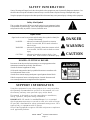
IMPORTANT: CE stands for certified Europe. It is a standard
which equipment must meet or exceed in order to be sold in Europe.
CE provides a benchmark for safety and manufacturing issues. CE is
required only on equipment sold in Europe.
Chore-Time Equipment recognizes CE Mark and pursues compliance
in all applicable products.
SUPPORT INFORMATION

AGRI-TIME
TM
Control Instruction
Page 3
SAFETY INFORMATION
Caution, Warning and Danger Decals have been placed on the equipment to warn of potentially dangerous situations. Care
should be taken to keep this information intact and easy to read at all times. Replace missing or damaged safety signs.
Using the equipment for purposes other than specified in this manual may cause personal injury or damage to the equipment.
Safety–Alert Symbol
This is a safety–alert symbol. When you see this symbol on your equipment, be alert
to the potential for personal injury. Chore-Time equipment is designed to be installed
and operated as safely as possible...however, hazards do exist.
DANGER
WARNING
CAUTION
Signal Words
Signal words are used in conjunction with the safety–alert symbol to identify the
severity of the warning.
DANGER..........indicates an imminently hazardous situation
which, if not avoided, WILL result in death or
serious injury.
WARNING .......indicates a potentially hazardous situation which,
if not avoided, COULD result in death or serious
injury.
CAUTION ........indicates a hazardous situation which, if not
avoided, MAY result in minor or moderate injury.
DANGER—ELECTRICAL HAZARD
Disconnect electrical power before inspecting or servicing equipment unless
maintenance instructions specifically state otherwise.
Ground all electrical equipment for safety.
All electrical wiring must be done by a qualified electrician in accordance with
local and national electric codes.
Ground all non-current carrying metal parts to guard against electrical shock.
With the exception of motor overload protection, electrical disconnects and
over current protection are not supplied with the equipment.
Using this equipment for any other purpose or in a way not within
the operating recommendations specified in this manual will void
the warranty and may cause personal injury and/or death.
This manual is designed to provide comprehensive installation,
wiring, operation, and parts listing information.
IMPORTANT: CE stands for certified Europe. It is a standard
which equipment must meet or exceed in order to be sold in Europe.
CE provides a benchmark for safety and manufacturing issues. CE is
required only on equipment sold in Europe.
Chore-Time Equipment recognizes CE Mark and pursues compliance
in all applicable products.
SUPPORT INFORMATION

AGRI-TIME
TM
Control Instruction
Page 4
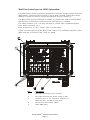
Meal-Time Control (part no. 34385) Information:
The Meal-Time Control is primarily designed to meet the feeding needs of broiler
applications. The Meal-Time Control is set up with Channel 1 being the feeder
channel. Feeder line motors should be powered only by Channel 1.
The Meal-Time channel (Channel 1) allows any feeder line that is running when
the run time is finished to continue to run until the line is satified.
The other channels (2,3, & 4) may be used to control other equipment (lights,
fans, water solenoids, etc.).
Each channel has a 2 H.P. (max.), 230 V. power relay.
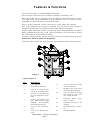
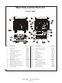
Figure 1 shows the front of the Meal-Time Control. The individual switches, pilot
lights and the 4-Channel Time Clock are noted.
Key Description
1 Pilot lights indicating active channels.
2 Pilot light indicating the power switch is “ON”.
3 Switches used to set individual Channels to
MANUAL, OFF, or TIME CLOCK mode.
4 Meal-Time Control Power Switch
5 AGRI-TIME Timer

AGRI-TIME
TM
Control Instruction
Page 4
Meal-Time Control (part no. 34385) Information:
The Meal-Time Control is primarily designed to meet the feeding needs of broiler
applications. The Meal-Time Control is set up with Channel 1 being the feeder
channel. Feeder line motors should be powered only by Channel 1.
The Meal-Time channel (Channel 1) allows any feeder line that is running when
the run time is finished to continue to run until the line is satified.
The other channels (2,3, & 4) may be used to control other equipment (lights,
fans, water solenoids, etc.).
Each channel has a 2 H.P. (max.), 230 V. power relay.
Figure 1 shows the front of the Meal-Time Control. The individual switches, pilot
lights and the 4-Channel Time Clock are noted.
Key Description
1 Pilot lights indicating active channels.
2 Pilot light indicating the power switch is “ON”.
3 Switches used to set individual Channels to
MANUAL, OFF, or TIME CLOCK mode.
4 Meal-Time Control Power Switch
5 AGRI-TIME Timer

AGRI-TIME
TM
Control Instruction
Page 5
Features & Functions
- The Agri Timer has (4) programmable channels.
- Each channel can have up to 8 events (feedings, waterings, etc.).
- Each event will have a start time and run time programmed into the timer.
The start times are programmed in hours/minutes. The run times are pro-
grammed in hours/minutes or minutes/seconds.
- Any or all the channels can be set up as an every other day channel.
- Two “AAA” batteries are used as a backup only for time of day if power is
temporarily removed. The batteries should be replaced annually.
Battery replacement procedure: Cut the wire tie to remove batteries. Replace
with new batteries (observe + and - poles of battery). Use a wire tie to secure
the new batteries in the battery holder.
- Program settings will be stored in memory until a program change is made.
Power loss will not erase the programs.
- The Start Time, Run Time, and Channel Select buttons have dual functions.
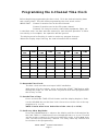
Legend: Figure 1.
Key Description
1 P.M. Indicator
2 Hour/Minute Indicator
3 Used to set time of day,
a.m./p.m., and skip mode.
4 Used to set start time and
to erase individual opera-
tions.
5 Used to set length of run
time. Also used to toggle
between hours/minutes
and minutes/seconds.
6 Used to set hours/min-
utes.
7 Used to set minutes/sec-
onds
8 Used to advance to next
event in channel.
9 Displays the event num-
ber being programmed.
10 Used to advance through
the channels. Also used
to set skip channel.
11 Indicates which chan-
nel(s) is active.
12 Indicates the day to be
skipped.
13 Minutes/Seconds Indica-
tor
14 Display Window
Figure 1.

AGRI-TIME
TM
Control Instruction
Page 5
Features & Functions
- The Agri Timer has (4) programmable channels.
- Each channel can have up to 8 events (feedings, waterings, etc.).
- Each event will have a start time and run time programmed into the timer.
The start times are programmed in hours/minutes. The run times are pro-
grammed in hours/minutes or minutes/seconds.
- Any or all the channels can be set up as an every other day channel.
- Two “AAA” batteries are used as a backup only for time of day if power is
temporarily removed. The batteries should be replaced annually.
Battery replacement procedure: Cut the wire tie to remove batteries. Replace
with new batteries (observe + and - poles of battery). Use a wire tie to secure
the new batteries in the battery holder.
- Program settings will be stored in memory until a program change is made.
Power loss will not erase the programs.
- The Start Time, Run Time, and Channel Select buttons have dual functions.
Legend: Figure 1.
Key Description
1 P.M. Indicator
2 Hour/Minute Indicator
3 Used to set time of day,
a.m./p.m., and skip mode.
4 Used to set start time and
to erase individual opera-
tions.
5 Used to set length of run
time. Also used to toggle
between hours/minutes
and minutes/seconds.
6 Used to set hours/min-
utes.
7 Used to set minutes/sec-
onds
8 Used to advance to next
event in channel.
9 Displays the event num-
ber being programmed.
10 Used to advance through
the channels. Also used
to set skip channel.
11 Indicates which chan-
nel(s) is active.
12 Indicates the day to be
skipped.
13 Minutes/Seconds Indica-
tor
14 Display Window
Figure 1.

AGRI-TIME
TM
Control Instruction
Page 6
CHANNEL 1 CHANNEL 2 CHANNEL 3 CHANNEL 4
RUN
TIME
RUN
TIME
RUN
TIME
RUN
TIME
START
TIME
START
TIME
START
TIME
START
TIME
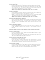
Programming the 4-Channel Time Clock
Before beginning programming the time clock, fill in the desired starting times
and running times. This will make programming the clock much easier.
IMPORTANT: Channel 1 must be used as the feed channel.
Channel 2 must be used as the fill system channel.
Channels 3 & 4 may be used to control other equipment, lights, etc.
A start time and a run time must be entered for each desired operation. If either
are missing or incomplete, the operation will be ignored.
The display must be flashing in order to make any program changes.
When the display stops flashing, the new infomation will be added.
To Reset the Time Clock:
The time clock must be reset upon initial installation.
With power off to the system, press and hold the START TIME button while
turning the power on. This will erase any entries that were programmed in
the factory or field.
To Set the Time of Day:
Press and hold the TIME OF DAY button until the display begins to flash.
Use the HR/MIN key on the time clock. Be sure to set the clock to the ap-
propriate a.m. or p.m.
NOTE: Entries must be on both sides of the colon (i.e. 01:20).
To Set Every Other Day Mode:
Press the HR/MIN button to advance the display until the indicator beside
the EOD TODAY is illuminated. Press the appropriate a.m. or p.m. This will
set the proper sequence for the every-other-day mode. It does not, how-
ever, set the every-other-day Channel. The every-other-day Channel will
be set later in the programming.

AGRI-TIME
TM
Control Instruction
Page 6
CHANNEL 1 CHANNEL 2 CHANNEL 3 CHANNEL 4
RUN
TIME
RUN
TIME
RUN
TIME
RUN
TIME
START
TIME
START
TIME
START
TIME
START
TIME
Programming the 4-Channel Time Clock
Before beginning programming the time clock, fill in the desired starting times
and running times. This will make programming the clock much easier.
IMPORTANT: Channel 1 must be used as the feed channel.
Channel 2 must be used as the fill system channel.
Channels 3 & 4 may be used to control other equipment, lights, etc.
A start time and a run time must be entered for each desired operation. If either
are missing or incomplete, the operation will be ignored.
The display must be flashing in order to make any program changes.
When the display stops flashing, the new infomation will be added.
To Reset the Time Clock:
The time clock must be reset upon initial installation.
With power off to the system, press and hold the START TIME button while
turning the power on. This will erase any entries that were programmed in
the factory or field.
To Set the Time of Day:
Press and hold the TIME OF DAY button until the display begins to flash.
Use the HR/MIN key on the time clock. Be sure to set the clock to the ap-
propriate a.m. or p.m.
NOTE: Entries must be on both sides of the colon (i.e. 01:20).
To Set Every Other Day Mode:
Press the HR/MIN button to advance the display until the indicator beside
the EOD TODAY is illuminated. Press the appropriate a.m. or p.m. This will
set the proper sequence for the every-other-day mode. It does not, how-
ever, set the every-other-day Channel. The every-other-day Channel will
be set later in the programming.

AGRI-TIME
TM
Control Instruction
Page 7
To Set a Start Time:
Press and hold the START TIME button until the display starts flashing.
Enter the start time for the first channel using the buttons in the SET TIME
area of the time clock. The start times will be set in hours and minutes. Be
sure to set the appropriate a.m. or p.m. settings.
NOTE: Entries must be on both sides of the colon (i.e. 01:20).
To Enter a Run Time:
Use the buttons in the SET TIME area of the time clock. The run times may
be set in minutes/seconds or hours/minutes (i.e. 01:20).
NOTE: To set the run times in minutes/seconds, press and hold the RUN
TIME button until the indicator beside MIN/SEC is illuminated.
NOTE: Entries must be on both sides of the colon (i.e. 01:20).
To Assign Skip Day Mode to a Channel:
Press and hold the CHANNEL SELECT button until the appropriate CHAN-
NEL indicator starts to flash. To remove skip day mode from a channel,
press and hold the CHANNEL SELECT button until the indicator stops
flashing.
To Move Through a Channel:
Press the ADVANCE button to move to the next event in a channel. The
EVENT NUMBER display window changes as the ADVANCE button is
pressed.
Follow the steps above to set the remainder of the channels and events.
To Erase a Single Event:
Press the CHANNEL SELECT button and the ADVANCE button to select
the event you wish to remove.
Press and hold the START TIME button until the display shows bars. This
will remove appropriate start time and run time.
To Erase All Start Times and Run Times:
Remove power to the Control Box.
Press and hold the START TIME button (for approximately 5 seconds)
while turning power on to the Control Box. This should remove all entries
from the program. However, the time of day will not be erased.
To Review the Program:
Press and hold the START TIME button until the display begins to flash.
Using the START TIME, RUN TIME, ADVANCE, and CHANNEL SELECT
buttons you can view each of the programmed entries (events).

AGRI-TIME
T M
Cont rol Instructi on
Page 8
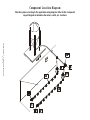
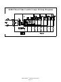
Component Location Diagram
Wire the system according to the applicable wiring diagram. Refer to this Component
Layout Diagram to determine the motor, switch, etc. locations.

AGRI-TIME
T M
Cont rol Instructi on
Page 8
Component Location Diagram
Wire the system according to the applicable wiring diagram. Refer to this Component
Layout Diagram to determine the motor, switch, etc. locations.

AGRI-TIME
TM
Control Instruction
Page 9
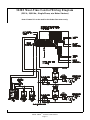
34385 Meal-Time Control Wiring Diagram
(230 V., 50/60 Hz., Single Phase, w/o Motor Starters)
Note: Channel 1 is to be used for the feeder line motors only.

AGRI-TIME
TM
Control Instruction
Page 9
34385 Meal-Time Control Wiring Diagram
(230 V., 50/60 Hz., Single Phase, w/o Motor Starters)
Note: Channel 1 is to be used for the feeder line motors only.

AGRI-TIME
T M
Cont rol Instructi on
Page 10
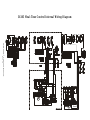
34385 Meal-Time Control Internal Wiring Diagram

AGRI-TIME
T M
Cont rol Instructi on
Page 10
34385 Meal-Time Control Internal Wiring Diagram
La pagina si sta caricando...
La pagina si sta caricando...
La pagina si sta caricando...
La pagina si sta caricando...
-
 1
1
-
 2
2
-
 3
3
-
 4
4
-
 5
5
-
 6
6
-
 7
7
-
 8
8
-
 9
9
-
 10
10
-
 11
11
-
 12
12
-
 13
13
-
 14
14
-
 15
15
-
 16
16
-
 17
17
-
 18
18
-
 19
19
-
 20
20
-
 21
21
-
 22
22
-
 23
23
-
 24
24


