
A
Panoramica hardware e connessioni
1
Pulsanti e LED
•
Il posizionamento del pulsante personalizzabile sulla tastiera può
essere impostato in 14 confi gurazioni diverse, combinando 4
pulsanti su 8 pulsanti; L'esempio mostra i 10 più comunemente
usati. Utilizzare i tasti che vengono nella dimensione di un pulsante
o due pulsanti per creare un layout di tastiera desiderato.
•
Il LED si illumina di arancione per indicare che l’alimentazione è presente.
•
Il LED si illumina di bianco per indicare che il tastierino è in funzione.
•
Il LED lampeggia in arancione e bianco per indicare l'aggiornamento
F / W.
2
Indicatore sistema LED
•
LAN: Il LED si illumina di verde per indicare che la LAN è connessa.
•
Link: Il LED si illumina di verde per indicare che la Control Box è
connessa.
*
Se il LED LAN si accende in verde e il LED Link non è attivo, la
Control Box non è collegata.
** Se entrambi i LED non sono attivi, la rete non è collegata.
3
Tasto Reset
Questo tasto a semi-incasso può essere premuto per ripristinare le
impostazioni di rete.
4
Per alimentazione CC
Inserire l’alimentatore nell'alimentazione di corrente continua.
5
Interruttori ID
•
Due interruttori ID: azzurro per tastiera e nero per la centrale di
controllo.
6
Porta LAN
•
La porta RJ-45 è utilizzata per la connessione LAN.
•
Se non viene assegnato un IP entro 30 secondi, verranno utilizzate
le impostazioni IP predefi nite:
IP: 192.168.0.60 / maschera: 255.255.255.0
•
Power-over-Ethernet è supportato per alimentare la tastiera con un
interruttore PoE.
B
Installazione
1. Assegnare i numeri ID regolando gli switch ID del VK108US.
L'interruttore ID blu serve all’impostazione del numero di
identifi cazione proprio della tastiera. L'interruttore ID nero serve
per impostare con quale Control Box abbinarsi. Fino a 8 tastiere
VK108US possono essere abbinate a una Control Box della serie
VK.
2. Collegare l'alimentazione CC sul VK108US ad una presa elettrica
con l'alimentatore o utilizzare PoE per alimentare l'unità.
3. Collegare il cavo Ethernet sul VK108US alla LAN.
4. Avvitare la tastiera all'apertura della parete.
5. Disporre i cappucci dei tasti nelle posizioni di confi gurazione della
tastiera desiderate. Corrisponde alla confi gurazione della tastiera
sulla tastiera con il piano di layout nel ATEN Confi gurator (VK6000).
6. Utilizzare ATEN Confi gurator per la confi gurazione della tastiera.
Una volta completata la confi gurazione e caricata, verifi care che i
LED LAN e Link si accendano in verde per indicare la connessione
corretta.
7. Fissare il frontalino dell'alloggiamento della tastiera.
Informazioni sull'alimentatore
1
Tagliare l'estremità del connettore dell'adattatore di alimentazione.
2
Togliere 5 mm (0,5 cm) dell'isolamento del cavo dell'adattatore di
alimentazione per esporre due fi li:un fi lo +5V e un fi lo di Massa
(messa a terra).
3
Inserire il fi lo +5V e quello di Massa ben stretti nel connettore del
blocco terminali con 2 attacchi.
Nota: Per poter determinare la polarità dei fi li esposti (ad esempio
+5V o Massa) usare un voltmetro.
VK108US ATEN Sistema di controllo - tastierino 8 tasti (US, 1 Gang)
www.aten.com
A
Aspectos generales del hardware y conexiones
1
Botones y LED
•
La colocación personalizable de los botones en el teclado se puede
establecer en 14 confi guraciones diferentes, con la combinación de
4 botones a 8 botones; el ejemplo muestra los 10 más utilizados.
Utilice los botones que vienen con el tamaño de 1 botón o 2
botones para crear el diseño de teclado deseado.
•
El LED se ilumina en naranja para indicar que la alimentación está
encendida.
•
El LED se enciende en blanco para indicar que el teclado está en
funcionamiento.
•
El LED parpadea en naranja y blanco para indicar la actualización del
fi rmware.
2
Indicador LED del sistema
•
LAN: El LED se ilumina en verde para indicar que la LAN está
conectada.
•
Enlace: El LED se ilumina en verde para indicar que la caja de control
está conectada.
*
Si el LED LAN se enciende en verde y el LED Link está inactivo, la
caja de control no está conectada.
** Si ambos LEDs están inactivos, la red no está conectada.
3
Pulsador para restablecer
Este pulsador semiempotrado puede ser presionado para restablecer
la confi guración de red.
4
Alimentación DC
Conecte el adaptador de alimentación a la entrada de alimentación
DC.
5
Conmutadores de identifi cación
•
Dos conmutadores de identifi cación: azul para el teclado y negro
para la caja de control.
6
Puerto LAN
•
El puerto RJ-45 se utiliza para la conexión de LAN.
•
Si dentro de los próximos 30 segundos no se asigna ninguna IP, se
utilizará la dirección IP predeterminada:
IP: 192.168.0.60 / máscara: 255.255.255.0
•
Power-over-Ethernet es soportado para alimentar el teclado con un
conmutador PoE.
B
Instalación del teclado
1. Asigne números de ID ajustando los conmutadores de ID en el
VK108US. El conmutador del identifi cador azul es para establecer
el número de identifi cador propio del teclado. El conmutador de
identifi cador negro es para establecer con qué caja de control se
asociará. Se pueden asociar hasta 8 teclados VK108US con una
caja de control de la serie VK.
2. Conecte la alimentación DC del VK108US a una toma de corriente
con el adaptador de alimentación o utilice PoE para alimentar la
unidad.
3. Conecte el cable Ethernet del VK108US a la LAN.
4. Atornille el teclado al orifi cio de la pared.
5. Coloque las tapas de los botones en las posiciones de
confi guración de teclado deseadas. Haga coincidir la confi guración
del teclado con el plan de distribución en el Confi gurador ATEN
(VK6000).
6. Utilice el Confi gurador ATEN para la confi guración del teclado.
Cuando se haya completado y cargado la confi guración,
compruebe si los LED LAN y Link se iluminan en verde para indicar
que la conexión se ha realizado con éxito.
7. Coloque la placa frontal de la carcasa del teclado.
Información sobre la fuente de alimentación
1
Corte el extremo del conector del adaptador de alimentación.
2
Quite 5 mm (0,5 cm) de la cubierta aislante del cable del adaptador
de alimentación para exponer dos cables: un cable + 5V y un cable
GND (tierra).
3
Inserte fi rmemente los cables expuestos de + 5V y el cable GND en
el Conector de bloque de terminales de 2 pines suministrado.
Nota: Un método para determinar la polaridad de un cable expuesto
(es decir, + 5V o GND) es utilizando un voltímetro.
Sistema de control VK108US ATEN - Teclado de 8 botones (EE.UU., 1 Gang)
www.aten.com
A
Hardwareübersicht und Anschlüsse
1
Tasten und LED
•
Die anpassbare Tastenanordnung auf dem Tastenfeld kann in
14 verschiedenen Konfi gurationen eingerichtet werden, mit
Kombination von 4 Tasten bis 8 Tasten. Das Beispiel zeigt die 10 am
häufi gsten verwendeten. Verwenden Sie die Tasten in der Größe
von 1 Taste oder 2 Tasten, um ein gewünschtes Tastenfeld-Layout zu
erstellen.
•
Die LED leuchtet orange, um anzuzeigen, dass die Stromversorgung
eingeschaltet ist.
•
Die LED leuchtet weiß, um anzuzeigen, dass das Tastenfeld in
Betrieb ist.
•
Die LED blinkt orange und weiß, um die F/W-Aktualisierung anzuzeigen.
2
System LED-Anzeige
•
LAN: Die LED leuchtet grün, um anzuzeigen, dass das LAN
angeschlossen ist.
•
Link: Die LED leuchtet grün, um anzuzeigen, dass die Kontrollbox
angeschlossen ist.
*
Wenn die LAN LED grün leuchtet und die Link LED inaktiv ist, ist die
Kontrollbox nicht angeschlossen.
** Wenn beide LEDs inaktiv sind, ist das Netzwerk nicht
angeschlossen.
3
Reset-Taste
Diese partiell vertiefte Taste kann zum Rücksetzen der
Netzwerkeinstellungen gedrückt werden.
4
Gleichstrom
Stecken Sie den Netzadapter in den DC-Eingang.
5
ID Schalter
•
Zwei ID-Schalter: blau für die Tastatur und schwarz für die
Kontrollbox.
6
LAN Port
•
Der RJ-45-Port wird für den LAN-Anschluss verwendet.
•
Wird innerhalb der folgenden 30 Sekunden keine
IP-Adresse zugeordnet, werden die voreingestellten IP-Einstellungen
verwendet:
IP: 192.168.0.60 / Maske: 255.255.255.0
•
Power-over-Ethernet wird unterstützt, um das Tastenfeld über einen
PoE-Switch zu versorgen.
B
Tastenfeld Installation
1. Weisen Sie ID-Nummern durch Anpassen der ID-Schalter am
VK108US zu. Der blaue ID-Schalter dient zur Einstellung der ID-
Nummer des Tastenfelds. Der schwarze ID-Schalter dient zur
Einstellung, mit welcher Kontrollbox gekoppelt werden soll. Bis zu
8 VK108US Tastenfelder können mit einer Kontrollbox der VK-Serie
gekoppelt werden.
2. Verbinden Sie die DC-Stromversorgung des VK108US mit einer
Steckdose mit dem Netzteil oder verwenden Sie PoE, um das Gerät
mit Strom zu versorgen.
3. Verbinden Sie das Ethernet-Kabel am VK108US mit dem LAN.
4. Schrauben Sie das Tastenfeld an die Wandöffnung.
5. Ordnen Sie die Tastenkappen in die gewünschten
Bedienfeldpositionen an. Passen Sie die Tastaturkonfi guration
auf dem Tastenfeld an den Layoutplan im ATEN Confi gurator
(VK6000) an.
6. Verwenden Sie den ATEN Confi gurator für die
Tastaturkonfi guration. Wenn die Konfi guration abgeschlossen und
hochgeladen ist, überprüfen Sie, ob die LAN- und Link-LEDs grün
leuchten, um eine erfolgreiche Verbindung anzuzeigen.
7. Befestigen Sie die Frontplatte des Tastenfeldes.
Informationen zur Stromversorgung
1
Schneiden Sie das Anschlussende des Netzkabels ab.
2
Isolieren Sie 5 mm (0,5 cm) des Netzteilkabels ab, sodass zwei
Drähte freiliegen:ein +5-V-Draht und ein Erdungsdraht.
3
Stecken Sie den freigelegten +5-V-Draht und den Erdungsdraht
sicher in den 2-poligen Anschluss am Anschlussblock.
Hinweis: Sie können die Polarität des freigelegten Drahtes (z. B. +5
V oder Erde) beispielsweise mit einem Spannungsmesser
ermitteln.
VK108US ATEN Kontrollsystem - 8-Tasten Tastenfeld (US, 1 Serie)
www.aten.com
A
Vue d'ensemble du matériel et
connexions
1
Boutons et LED
•
Le positionnement personnalisé des boutons sur le clavier peut être
confi guré de 14 façons différentes, avec une combinaison de 4
boutons à 8 boutons; l'exemple montre les 10 confi gurations les plus
couramment utilisées. Utilisez des boutons de la taille de 1 bouton ou
2 boutons pour créer une disposition de clavier souhaitée.
•
La LED s'allume en orange pour indiquer que l'alimentation est
allumée.
•
La LED s'allume en blanc pour indiquer que le clavier est en marche.
•
La LED clignote en orange et en blanc pour indiquer la mise à niveau
F/W.
2
Indicateur LED du système
•
LAN : La LED s'allume en vert pour indiquer que le LAN est
connecté.
•
Link (Liaison) : La LED s'allume en vert pour indiquer que le boîtier
de contrôle est connecté.
*
Si la LED LAN s'allume en vert et que la LED Liaison (Link) est
inactive, le boîtier de contrôle n'est pas connecté.
** Si les deux LED sont inactives, le réseau n'est pas connecté.
3
Bouton poussoir de réinitialisation
Ce bouton poussoir semi-encastré peut être actionné pour réinitialiser
les paramètres réseau.
4
Courant continu
Branchez l'adaptateur secteur à l'entrée de courant CC.
5
Commutateurs ID
•
Deux commutateurs ID : bleu pour le clavier et noir pour le boîtier
de contrôle.
6
Port LAN
•
Le port RJ-45 est utilisé pour la connexion LAN.
•
Si aucune adresse IP n’est attribuée dans l’intervalle de 30 secondes,
les paramètres IP par défaut seront utilisés :
IP : 192.168.0.60 / masque : 255.255.255.0
•
PoE (Power-over-Ethernet) est pris en charge pour alimenter le clavier
avec un commutateur PoE.
B
Installation du clavier
1. Attribuez des numéros d'identifi cation en ajustant les
commutateurs ID sur le VK108US. Le commutateur ID bleue permet
de défi nir le numéro d'ID du clavier. Le commutateur ID noir permet
de défi nir le boîtier de contrôle avec lequel il sera associé. Jusqu'à 8
claviers VK108US peuvent être associés avec un boîtier de contrôle
de la série VK.
2. Connectez l'alimentation CC du VK108US à une prise secteur avec
l'adaptateur secteur ou utilisez PoE pour alimenter l'appareil.
3. Connectez le câble Ethernet sur le VK108US au LAN.
4. Vissez le clavier sur l'ouverture du mur.
5. Disposez les capuchons des boutons dans les positions de
confi guration du clavier souhaitées. Faites correspondre la
confi guration du clavier sur le clavier avec le plan de disposition
dans le ATEN Confi gurator (VK6000).
6. Utilisez ATEN Confi gurator pour la confi guration du clavier. Lorsque
la confi guration est terminée et téléchargée, vérifi ez si les LED LAN
et Link (Liaison) s'allument en vert pour indiquer une connexion
réussie.
7. Fixez la façade du boîtier du clavier.
Informations relatives à l’alimentation
1
Coupez l’extrémité du connecteur de l’adaptateur secteur.
2
Dénudez 5mm (0,5 cm) de gaine isolante sur le câble de
l’adaptateur secteur pour mettre à nu deux fi ls :un fi l +5V et un fi l
GND (masse).
3
Insérez le fi l +5V et le fi l GND dénudés dans le connecteur du
bornier 2 broches fourni.
Remarque : Une des méthodes pour déterminer la polarité d'un
fi l dénudé (ex : +5V ou GND) consiste à utiliser un
voltmètre.
Système de contrôle VK108US ATEN - Clavier à 8 boutons (US, 1 Gang)
www.aten.com
A
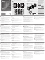
Hardware Overview and Connections
1
Buttons and LED
•
The customizable button placement on the keypad can be setup
in 14 different confi gurations, with combination of 4 buttons to 8
buttons; the example shows the 10 most commonly used. Use the
buttons that come in the size of 1 button or 2 buttons to create a
desired keypad layout.
•
The LED lights orange to indicate the power is on.
•
The LED lights white to indicate the keypad is in operation.
•
The LED blinks orange and white to indicate F/W upgrading.
2
System LED Indicator
•
LAN: The LED lights green to indicate the LAN is connected.
•
Link: The LED lights green to indicate the Control Box is connected.
* If the LAN LED lights green and the Link LED are inactive, the Control
Box is not connected.
** If both LEDs are inactive, the network is not connected.
3
Reset Pushbutton
This semi-recessed pushbutton can be pressed to reset the network
settings.
4
DC Power
Plug the power adaptor into the DC power input.
5
ID Switches
•
Two ID switches: blue for the keypad and black for the Control Box.
6
LAN Port
•
The RJ-45 port is used for LAN connection.
•
If no IP is assigned within 30 seconds, the default IP settings will be
used:
IP: 192.168.0.60 / mask: 255.255.255.0
•
Power-over-Ethernet is supported to power the keypad with a PoE
switch.
B
Keypad Installation
1. Assign ID numbers by adjusting the ID switches on the VK108US.
The blue ID switch is to set the keypad’s own ID number. The black
ID switch is to set which Control Box it will pair with. Up to 8
VK108US Keypads can pair with a VK series Control Box.
2. Connect the DC Power on the VK108US to a power outlet with the
power adaptor, or use PoE to power the unit.
3. Connect the Ethernet cable on the VK108US to the LAN.
4. Screw the keypad to the wall opening.
5. Arrange button caps into the desired keypad confi guration
positions. Match the keypad confi guration on the keypad with the
layout plan in the ATEN Confi gurator (VK6000).
6. Use ATEN Confi gurator for the keypad confi guration. When the
confi guration is completed and uploaded, check if the LAN and Link
LEDs light green to indicate successful connection.
7. Attach the faceplate of the keypad housing.
Power Supply Information
1
Cut the connector end of the power adapter.
2
Strip 5mm (0.5 cm) off the insulation cover of the Power Adapter
cable to expose two wires: a +5V wire and a GND (grounding)
wire.
3
Insert the exposed +5V wire and GND wire tightly into the provided
2-pin Terminal Block Connector.
Note: One method to determine an exposed wire’s polarity (i.e., +5V
or GND) is by using a voltmeter.
VK108US ATEN Control System - 8-Button Keypad (US, 1 Gang)
www.aten.com
B
Package Contents
1 VK108US Keypad
1 Power Adapter
1 Button Pack
1 Terminal Block
1 Faceplate
1 User Instructions
Front View
Keypad Layout Example
Keypad Installation
© Copyright 2017 ATEN
®
International Co., Ltd.
ATEN and the ATEN logo are trademarks of ATEN International Co., Ltd. All rights reserved. All
other trademarks are the property of their respective owners.
This product is RoHS compliant.
Part No. PAPE-1223-J20G Printing Date: 07/2017
ATEN Control System - 8-Button Keypad
(US, 1 Gang)
Quick Start Guide
VK108US
ATEN VanCryst
™
Support and Documentation Notice
All information, documentation, fi rmware,
software utilities, and specifi cations
contained in this package are subject to
change without prior notifi cation by
the manufacturer.
To reduce the environmental impact of our
products, ATEN documentation and software
can be found online at
http://www.aten.com/download/
Technical Support
www.aten.com/support
이 기기는 업무용(A급) 전자파적합기기로서 판매자 또는
사용자는 이 점을 주의하시기 바라며, 가정외의 지역에
서 사용하는 것을 목적으로 합니다.
Scan for
more information
EMC Information
FEDERAL COMMUNICATIONS COMMISSION INTERFERENCE
STATEMENT:
This equipment has been tested and found to comply with the limits
for a Class A digital device, pursuant to Part 15 of the FCC Rules.
These limits are designed to provide reasonable protection against
harmful interference when the equipment is operated in a commercial
environment. This equipment generates, uses, and can radiate radio
frequency energy and, if not installed and used in accordance with
the instruction manual, may cause harmful interference to radio
communications. Operation of this equipment in a residential area
is likely to cause harmful interference in which case the user will be
required to correct the interference at his own expense.
FCC Caution: Any changes or modifi cations not expressly approved by
the party responsible for compliance could void the user's authority to
operate this equipment.
Warning: Operation of this equipment in a residential environment
could cause radio interference.
Warning: This equipment is compliant with Class A of CISPR 32. In a
residential environment this equipment may cause radio interference.
Suggestion: Shielded twisted pair (STP) cables must be used with the
unit to ensure compliance with FCC & CE standards.
This device complies with Part 15 of the FCC Rules. Operation is subject
to the following two conditions:(1) this device may not cause harmful
interference, and(2) this device must accept any interference received,
including interference that may cause undesired operation.
A
Hardware Overview and Connections
1
2
5
3
6
4
47.67mm
68mm
28.2mm
+5V
+5V
GND
GND
5mm
1
2
3
(+)
(-)
Power Supply Information
La pagina si sta caricando...
-
 1
1
-
 2
2


in altre lingue
- English: ATEN VK108US Quick start guide
- français: ATEN VK108US Guide de démarrage rapide
- español: ATEN VK108US Guía de inicio rápido
- Deutsch: ATEN VK108US Schnellstartanleitung
- русский: ATEN VK108US Инструкция по началу работы
- português: ATEN VK108US Guia rápido
- 日本語: ATEN VK108US クイックスタートガイド