Rockford Fosgate Car Amplifier X1 Manuale utente
- Tipo
- Manuale utente


INTRODUCTION
TABLE OF CONTENTS
2
Dear Customer,
Congratulations on your purchase of the world's finest brand of car audio amplifiers. At Rockford
Fosgate we are fanatics about musical reproduction at its best, and we are pleased you chose our
product. Through years of engineering expertise, hand craftsmanship and critical testing procedures,
we have created a wide range of products that reproduce music with all the clarity and richness you
deserve.
For maximum performance we recommend you have your new Rockford Fosgate product installed
by an Authorized Rockford Fosgate Dealer, as we provide specialized training through Rockford
Technical Training Institute (RTTI). Please read your warranty and retain your receipt and original
carton for possible future use.
Great product and competent installations are only a piece of the puzzle when it comes to your
system. Make sure that your installer is using 100% authentic installation accessories from
Connecting Punch in your installation. Connecting Punch has everything from RCA cables and
speaker wire to Power line and battery connectors. Insist on it! After all, your new system deserves
nothing but the best.
To add the finishing touch to your new Rockford Fosgate image order your Rockford accessories,
which include everything from T-shirts and jackets to hats and sunglasses.
To get a free brochure on Rockford Fosgate products and Rockford accessories,
in the U.S. call 480-967-3565 or FAX 480-967-8132.
For all other countries, call +001-480-967-3565 or FAX +001-480-967-8132.
PRACTICE SAFE SOUND™
Continuous exposure to sound pressure levels over 100dB may cause permanent
hearing loss. High powered auto sound systems may produce sound pressure
levels well over 130dB. Use common sense and practice safe sound.
Introduction . . . . . . . . . . . . . . . . . . . . . . . . 2
Safety Instructions . . . . . . . . . . . . . . . . . . . 3
Design Features . . . . . . . . . . . . . . . . . . . . . 4
Installation . . . . . . . . . . . . . . . . . . . . . . . 4-7
Installation Considerations . . . . . . . . . . . 4
Mounting Locations. . . . . . . . . . . . . . . . 5
Mounting the Amplifier . . . . . . . . . . . . . 5
Battery and Charging . . . . . . . . . . . . . . . 6
Wiring the System . . . . . . . . . . . . . . . . . 6
NOTE: Review each section for more detailed information.
If, after reading your manual, you still have questions regarding this product, we recommend that
you see your Rockford Fosgate dealer. If you need further assistance, you can call us direct at 1-800-
669-9899. Be sure to have your serial number, model number and date of purchase available when
you call.
The serial number can be found on the outside of the box. Please record it in the space provided
below as your permanent record. This will serve as verification of your factory warranty and may
become useful in recovering your unit if it is ever stolen.
Serial Number: _________________________________________
Model Number: ________________________________________
Operation . . . . . . . . . . . . . . . . . . . . . . . 8-10
Color Options. . . . . . . . . . . . . . . . . . . . . . 10
Troubleshooting . . . . . . . . . . . . . . . . . . . . 11
Accessories. . . . . . . . . . . . . . . . . . . . . . . . 12
Specifications . . . . . . . . . . . . . . . . . . . . . . 12
Limited Warranty Information. . . . . . . . . . 13
International Instructions . . . . . . . . . . . . . 14

SAFETY INSTRUCTIONS
CONTENTS OF CARTON
3
Visit our web site for the latest information on all Rockford products.
The password to get into the Type RF site is TYPERFUSA
GETTING STARTED
Welcome to Rockford Fosgate! This manual is designed to provide
information for the owner, salesperson and installer. For those of you who want quick information
on how to install this product, please turn to the Installation Section of this manual. Other
information can be located by using the Table of Contents. We, at Rockford Fosgate, have worked
very hard to make sure all the information in this manual is current. But, as we are constantly
finding new ways to improve our product, this information is subject to change without notice.
www.rockfordfosgate.com
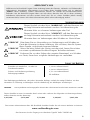
This symbol with “WARNING” is intended to alert the user to the
presence of important instructions. Failure to heed the
instructions will result in severe injury or death.
This symbol with “
CAUTION” is intended to alert the user to the
presence of important instructions. Failure to heed the
instructions can result in injury or unit damage.
CAUTION: To prevent injury and damage to the unit, please read and follow the
instructions in this manual. We want you to have enjoyment from this
system, not a headache.
CAUTION If you feel unsure about installing this system yourself, have it installed
by a qualified Rockford Fosgate technician.
CAUTION Before installation, disconnect the battery negative (-) terminal to
prevent damage to the unit, fire and/or possible injury.
!
!
!
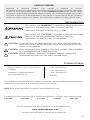
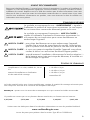
Either a model X1, X2 or X3 2-Channel
Amplifier
Installation & Operation Manual
Mounting Hardware Kit
1 3/32" Allen Wrench
1 1/8" Allen Wrench
1 3/16" Allen Wrench
RF Sticker
The hardware kit included with each amplifier contains the mounting hardware necessary to secure
the amplifier to the vehicle and to attach the cover to the heatsink.
NOTE: Refer to the specifications section for recommended fuse sizes.
This product may be covered by one or more of the following U.S. Patents, other patents pending:
4,467,288 5,673,000 5,751,823 5,936,467 6,097,249

4
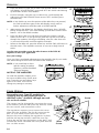
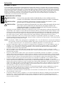
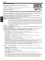
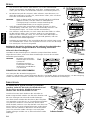
DESIGN FEATURES
INSTALLATION
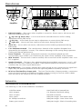
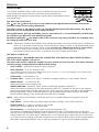
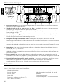
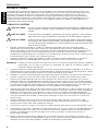
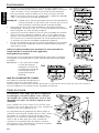
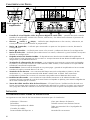
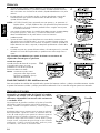
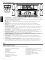
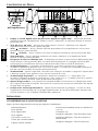
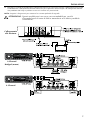
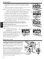
1. DSP LCD Display – Title screen when amplifier is turned on. Shows menus, sub-menus and
selections during DSP set-up.
2. (up) and (down) Keys – Use to scroll menus and sub-menus as well as making
adjustments during DSP set-up.
3. (left) Key – Use to back up one step in adjustments or menus during DSP set-up.
4. (right) Key – Use to enter into menus and sub-menus during DSP set-up.
5. Select Key – Use to select into menus, sub-menus and for finalizing adjustments during
DSP set-up.
6. Cast Aluminum Heatsink – The cast aluminum heatsink of the amplifier dissipates heat
generated by the amplifier's circuitry. The inherent advantage of this casting design optimizes
cooling and thermal performance.
7. Power Terminals – The power and ground connectors are platinum-plated and will
accommodate up to 4 AWG wire maximizing the input current capability of the amplifier.
8.
REM Terminal – This terminal is used to remotely turn-on and turn-off the amplifier when +12V
DC is applied.
9. Speaker Terminals – The heavy duty, platinum-plated terminal block connectors (+ and –) will
accept wire sizes from 8 AWG to 18 AWG. These platinum-plated connectors are immune to
corrosion that can cause signal deterioration.
10. RCA Input Jacks – The industry standard RCA jacks provide an easy connection for signal level
input. They are platinum-plated to resist the signal degradation caused by corrosion.
11. RCA Pass-Thru/Auxiliary Output Jacks – The Pass-Thru/Auxiliary Output provides a convenient
source for daisy-chaining an additional amplifier without running an extra set of RCA cables
from the front of the vehicle to the rear amplifier location.
INSTALLATION CONSIDERATIONS
The following is a list of tools needed for installation:
Volt/Ohm Meter
Wire strippers
Wire crimpers
Wire cutters
#2 Phillips screwdriver
Battery post wrench
Hand held drill w/assorted bits
1/8" diameter heatshrink tubing
Assorted connectors
Adequate Length—Red Power Wire
Adequate Length—Auto Power Wire
Adequate Length—Black Grounding Wire
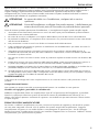
Top of
Amplifier

5
INSTALLA
TION
This section focuses on some of the vehicle considerations for installing your new Amplifier. Pre-
planning your system layout and best wiring routes will save installation time. When deciding on
the layout of your new system, be sure that each component will be easily accessible for making
adjustments.
CAUTION: If you feel unsure about installing this system yourself, have it installed
by a qualified technician.
CAUTION: Before installation, disconnect the battery negative (-) terminal to
prevent damage to the unit, fire and/or possible injury.
Before beginning any installation, follow these simple rules:
1. Be sure to carefully read and understand the instructions before attempting to install the unit.
2. For safety, disconnect the negative lead from the battery prior to beginning the installation.
3. For easier assembly, we suggest you run all wires prior to mounting your unit in place.
4. Route all of the RCA cables close together and away from any high current wires.
5. Use high quality connectors for a reliable installation and to minimize signal or power loss.
6. Think before you drill! Be careful not to cut or drill into gas tanks, fuel lines, brake or hydraulic
lines, vacuum lines or electrical wiring when working on any vehicle.
7. Never run wires underneath the vehicle. Running the wires inside the vehicle provides the best
protection.
8. Avoid running wires over or through sharp edges. Use rubber or plastic grommets to protect any
wires routed through metal, especially the firewall.
9. ALWAYS protect the battery and electrical system from damage with proper fusing. Install the
appropriate fuse holder and fuse on the +12V power wire within 18” (45.7 cm) of the battery
terminal.
10. When grounding to the chassis of the vehicle, scrape all paint from the metal to ensure a good,
clean ground connection. Grounding connections should be as short as possible and always be
connected to metal that is welded to the main body, or chassis, of the vehicle.
MOUNTING LOCATIONS
Engine Compartment
Never mount this unit in the engine compartment. Mounting the unit in the engine compartment
will void your warranty.
Trunk (preferred) and Passenger Compartment Mounting
Though preferred mounting is to the floor of the trunk, the Type RF amplifiers can be mounted in
any orientation. This is due to it's unique internal cooling system which uses Backset inlets and
outlets for optimized air movement even in a limited surrounding space.
MOUNTING AMPLIFIER
Mounting and wiring the amplifier requires the removal of the cover plate. Do this by removing the
four (4) 3/16 head Allen screws at each top corner of the amplifier. Set the amplifier in the place it is
to be mounted and mark the mounting holes. Review the Installation Considerations to safely install
your unit. Wire and mount your amplifier, then, reinstall the cover plate.
!
!

6
INSTALLA
TION
BATTERY AND CHARGING
Amplifiers will put an increased load on the vehicle's battery and charging system. We recommend
checking your alternator and battery condition to ensure that the electrical system has enough
capacity to handle the increased load of your stereo system. Stock electrical systems which are in
good condition should be able to handle the extra load of any Rockford Fosgate amplifier without
problems, although battery and alternator life can be reduced slightly. To maximize the performance
of your amplifier, we suggest the use of a heavy duty battery and an energy storage capacitor.
WIRING THE SYSTEM
CAUTION: If you do not feel comfortable with wiring your new unit, please see
your local Authorized Rockford Fosgate Dealer for installation.
CAUTION: Before installation, disconnect the battery negative (-) terminal to
prevent damage to the unit, fire and/or possible injury.
CAUTION: Avoid running power wires near the low level input cables, antenna,
power leads, sensitive equipment or harnesses. The power wires carry
substantial current and could induce noise into the audio system.
1. Plan the wire routing. Keep RCA cables close together but isolated from the amplifier's power
cables and any high power auto accessories, especially electric motors. This is done to prevent
coupling the noise from radiated electrical fields into the audio signal. When feeding the wires
through the firewall or any metal barrier, protect them with plastic or rubber grommets to
prevent short circuits. Leave the wires long at this point to adjust for a precise fit at a later time.
2. Prepare the RED wire (power cable) for attachment to the amplifier by stripping 1/2" of
insulation from the end of the wire. Insert the bared wire into the B+ terminal and tighten the set
screw to secure the cable in place.
NOTE: The B+ cable MUST be fused 18" or less from the vehicle's battery. Install the fuseholder under
the hood and prepare the cable ends as stated above. Connections should be water tight.
3. Trim the RED wire (power cable) within 18" of the battery and strip1/2"of insulation from the
end of the wire. Splice the fuseholder into the power line using appropriate inline connectors.
Use the section of cable that was trimmed earlier and connect it to the other end of the
fuseholder.
4. Strip 1/2" from the battery end of the power cable and crimp a large ring terminal to the cable.
Use the ring terminal to connect to the battery positive terminal. DO NOT install the fuse at
this time.
5. Prepare the BLACK wire (Ground cable) for attachment to the amplifier by stripping 1/2" of
insulation from the end of the wire. Insert the bared wire into the GND terminal and tighten the
set screw to secure the cable in place. Prepare the chassis ground by scraping any paint from
the metal surface and thoroughly clean the area of all dirt and grease. Strip the other end of the
wire and attach a ring connector. Fasten the cable to the chassis using a non-anodized screw
and a star washer.
6. Prepare the REM turn-on wire for connection to the amplifier by stripping 1/2" of insulation from
the wire end. Insert the bared wire into the REM terminal and tighten the set screw to secure the
cable into place. Connect the other end of the REM wire to a switched 12 volt positive source.
The switched voltage is usually taken from the source unit's accessory lead. If the source unit
does not have this output available, the recommended solution is to wire a mechanical switch
in line with a 12 volt source to activate the amplifier.
7. Securely mount the amplifier to the vehicle or amp rack. Be careful not to mount the amplifier
on cardboard or plastic panels. Doing so may enable the screws to pull out from the panel due
to road vibration or sudden vehicle stops.
8. Connect the source signal to the amplifier by plugging the RCA cables into the input jacks at the
amplifier.
9. Connect the speakers. Strip the speaker wires 1/2" and insert into the speaker terminal and
tighten the set screw to secure into place. Be sure to maintain proper speaker polarity. DO NOT
chassis ground any of the speaker leads as unstable operation may result.
!
!
!

7
INSTALLA
TION
10. Perform a final check of the completed system wiring to ensure that all connections are
accurate. Check all power and ground connections for frayed wires and loose connections
which could cause problems. Install the fuse into the fuseholder.
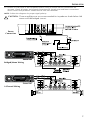
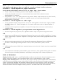
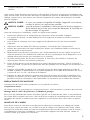
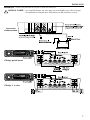
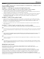
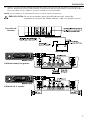
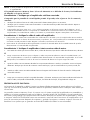
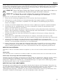
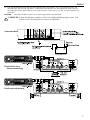
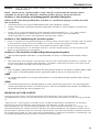
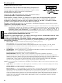
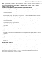
NOTE: Follow the diagrams for proper signal polarity.
CAUTION: These amplifiers are not recommended for impedance loads below 2Ω
stereo and 4Ω bridged (mono).
!
Power
Connection
Bridged/Mono Wiring
2-Channel Wiring

8
OPERATION
DSP FEATURES
The Type RF amplifiers offer a wide range of selections for the user to the
create a listening environment that meets their personal preference.
Read through the adjustment procedures to get the best results before making
final adjustments.
DSP BUTTON FUNCTIONS
The (up) and (down) keys move you up and down through the Menu Selections, between the
Selection settings and for Setting Adjustments.
The Select (center) or (right) key takes you into the individual Menu Selection settings. The (left)
key backs you out one step while in the setting selections.
During adjustments, pressing and holding a key for more than one (1) second will quickly scroll through
the selection in the direction of the button being held.
EXAMPLE: Holding the (up) button while in the Crossover Freq setting will allow you to quickly move
the setting upwards from 50 to 350.
NOTE:
Adjustments made to the amplifier setup will be saved after exiting the current menu or adjustment
screen. If no keypress is detected for 30 seconds after a change is made, it will automatically return
to the title screen and changes will be saved. To ensure any adjustments made are saved, always
exit the current menu or allow the 30 second timeout period. These settings can also be
permanently saved to one of five (5) locations using the GLOBAL SAVE feature.
DSP MENU & DEFAULTS
Opening Message – "ROCKFORD FOSGATE TYPE RF DSP" and "PRESS ANY KEY FOR SETUP MENU";
This shows when amplifier is turned on.
The menu order shown is when the amplifier has been turned on for the first time. This shows selections,
selection settings, setting adjustment and the default setting.
1. INPUT LEVEL – (Setting the amplifier's input sensitivity)
INPUT RANGE - HI or LO {Default is HI}
A LO setting is for a source unit output of less than or equal to 1.0 volts. A HI setting is for a source unit
output of greater than or equal to 1.1 volts.
GAIN LEVEL - 0-30 {Default is 30}
2. GLOBAL SAVE – (Used to save up to 5 individual complete settings in a non-volatile memory)
PRESET SELECT - 1-5 {Default is Ø}
Selects the preset memory spot to use.
PRESET PERFORM - PROTECT, SAVE, LOAD or RESTORE {Default is PROTECT}
Selects the feature to perform for the selected preset. PROTECT: Disables all actions on the selected
preset until changed by using the up/down keys. SAVE: Saves the settings currently in the amplifier to
the selected preset. LOAD: Loads the settings in the selected preset into the amplifier. RESTORE:
Restores all the settings in the selected preset to the factory defaults.
NOTE: Always wait for the display to read that the save is complete before turning power off to the
amplifier
3.
TIME DELAY – (Used to delay the signal output of either the Right, Left or Both channels)
SIGNAL SELECT - L CHAN, R CHAN or L+R CHAN
Selects the channel output for the signal delay.
DELAY ADJUST - 0-500 (setting in 20usec increments) {Default is Ø}
This setting is individually adjustable for each Signal Select with a signal delay of up to 500 ultra
seconds {0-10 milliseconds}. Settings made in either the L-CHAN or R CHAN select are additive to the
setting entered in L+R CHAN select. Adjusting the L or R Channel delays allows the user to off-center
or center the stereo imaging as desired, whereas the L+R Channel delay setting can be used to balance
the relative signal delay between two (2) separate amplifiers in systems using multiple amplifiers.

9
OPERATION
4. SUBSONIC – (Used to turn the subsonic filter on or off and adjust frequency)
SUBSONIC FILTER - ON or OFF {Default is OFF}
Setting this to "ON" engages a subsonic filter limiting the amount of low frequency information going
to the woofer with a -12dB/octave @ a variable 10 to 50Hz, adjustable in 1hz increments. This helps
prevent woofer damage due to over-excursion.
SUBSONIC FREQUENCY - 10-50 (setting in Hz) {Default is 50}
5. PUNCH EQ - (Setting the Bass and Treble output of the amplifier)
PUNCH BASS LEVEL - 0-18 (setting in dB) {Default is Ø}
PUNCH TREBLE LEVEL - 0-12 (setting in dB) {Default is Ø}
6. AUX OUTPUTS – (Setting the amplifier pass thru/auxiliary outputs)
NOTE: The frequency set in XOVER MODE is used here. This is not dependent on the mode that was set
in the XOVER MODE.
AUX OUT SELECT - ALL PASS, LOW PASS, HIGH PASS or DIRECT, {Default is ALL PASS}
Used to select the signal output of the Pass-Thru/Auxiliary Output RCA jacks between All Pass, High
Pass, Low Pass or Direct mode. In the High Pass or Low Pass mode, the frequency set in XOVER
MODE is used here. However, depending on the crossover set here, the Pass-Thru/Auxiliary Outputs
can be neutral (All Pass), the same or a *complimentary signal of the crossover type that was set in
XOVER MODE, or, set to DIRECT to allow the source signal to pass through without any processing
delay. All Pass or Direct routes the full bandwidth input signal to the auxiliary Pass-Thru RCA jacks.
All Pass routes a time-delayed replica of the input signal that is synchronized to the amplifier speaker
outputs. Direct routes the input signal with no time delay, and is useful for cascading multiple
amplifiers without incurring any cumulative signal delay.
NOTE: This feature is useful when separate amplifiers are used to drive the high and low frequency bands.
By setting the first (1st) amplifier to drive the low frequency, setting XOVER mode to Low Pass, and
selecting High Pass for the Pass-Thru/Auxiliary Output RCA jacks, the *complimentary signal will
be amplified by the second (2nd) amplifier.
*Complimentary Signal is a term used when the source signal is exactly split into two (2) separate
frequency bands, a high and low band, in such a way that the resultant high and low band signals can be
amplified separately to accurately reproduce the original signal. There is no loss or "notch" in the overall
frequency response due to the splitting. This type of processing optimizes reproduction of the original
source material and is only possible using linear phase DSP (digital signal processing).
7. XOVER MODE – (Crossover Settings)
XOVER MODE - ALL PASS, LOW PASS, HIGH PASS or DIRECT {Default is ALL PASS}
The crossover type can be adjusted between All Pass, Low Pass, High Pass or Direct mode. All Pass or
Direct routes the full bandwidth input signal to the speaker outputs. Direct routes the input signal with
no time delay to the speaker outputs.
NOTE: The frequency set here is also used for AUX OUTPUTS, no matter how the XOVER MODE was set.
XOVER FREQ (Frequency) - 50-350 (setting in Hz) {Default is 350}
Accessible only in LOW PASS and HIGH PASS modes. The crossover frequency can be adjusted
between 50-350Hz at a crossover slope of 48dB.
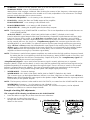
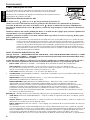
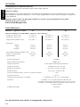
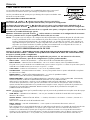
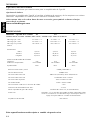
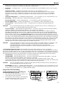
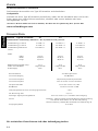
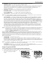
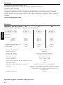
Example of making DSP adjustments.
This example will be showing an adjustment to the XOVER MODE.
1. Press the Select or (right) key to enter into the menu selections.
2. Use the (up) or (down) key to scroll
through the menu until "XOVER MODE"
shows on the screen.
1
2

10
OPERATION
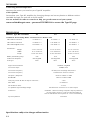
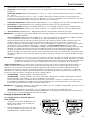
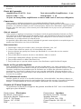
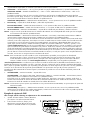
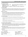
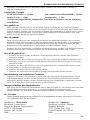
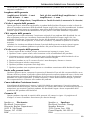
COLOR OPTIONS
Personalize your Type RF amplifier by
changing the top and corner plastics to
different colors. Available through our web
site or local retailer.
The corners can be changed by removing the screw
at the bottom, pull the old corner up and out, install
the new corner, and reinstall the screw.
The top plastic requires you to remove the cover
plate from the amplifier. Do this by removing the
four (4) 3/16" allen screws from each corner.
Remove the screw holding the top plastic in place,
pull the old top up and out, install the new top,
ensure the top fits into the notches at the back, and
reinstall the screw. Reinstall the cover plate and the
four (4) allen screws.
Allen
Screw
Screw
3. Press the Select or (right) key to enter into XOVER MODE. The screen
will display "XOVER MODE" at top and "SET: ALL PASS" with flashing
up and down arrows at the bottom.
4. For this example, using the (up) or (down) key, scroll through the
sub-menu until "HIGH PASS" shows next to "SET:" and then press
the Select key.
NOTE: If ALL PASS was set at this point and the Select key was pressed,
the DSP would have gone to the title display screen and no
further adjustment could be made to XOVER MODE.
5. After pressing the Select key, the display should now show "XOVER
FREQ" at top and "SET: 350" with flashing up and down arrows at the
bottom. 350 is the default number.
6. Press the (down) key to scroll down through the numbers until 80
shows next to "SET:". If you go too far, press the (up) key to scroll up
through the numbers. Pressing and holding a key for more than one
(1) second will quickly scroll through the selection.
7. When 80 has been set, press the Select key and the DSP will return to
the title screen. The amplifier crossover is now set to High Pass @
80Hz.
Use the same procedure to set the other features of the TYPE RF
amplifier to meet your application.
Save your settings
Once you have completed adjustments to the amplifier that fit your needs,
save these settings to one of the GLOBAL SAVE locations.
NOTE: If you need help or have
specific setting procedure
questions, contact Rockford
Technical Support.
MUTING THE AMPLIFIER
To mute the amplifier outputs, press
the (up) and (down) keys at the same
time. Press the (up) and (down) keys
again to un-mute. This will not
change any settings in memory.
5-6
7
3
4
4

11
TROUBLESHOOTING
NOTE: If you are having problems after installation follow the Troubleshooting procedures below.
If the display reads "Memory Error" or is difficult to read, see Display Problems at bottom.
Procedure 1: Check Amplifier for proper connections.
Verify that the LCD Display comes on. If it is on, skip to Step 2, if not continue.
1. Check in-line fuse on battery positive cable. Replace if necessary.
2. Verify that Ground connection is connected to clean metal of the vehicle’s chassis.
Repair/replace if necessary.
3. Verify there is 10.5 - 15.5 Volts present at the positive battery and remote turn-on cable. Verify
quality connections for both cables at amplifier, source unit, and battery/fuseholder.
Repair/replace if necessary.
Procedure 2: Check Amplifier for audio output.
1. Verify good RCA input connections at source unit and amplifier. Check entire length of cables
for kinks, splices, etc. Test RCA inputs for AC current with source unit on. Repair/replace if
necessary.
2. Disconnect RCA input from amplifier. Connect RCA input from test source unit directly to
amplifier input.
Procedure 3: Check Amplifier if you experience excess Engine Noise.
1. Route all signal carrying wires (RCA, Speaker cables) away from power and ground wires.
OR
2. Bypass any and all electrical components between the source unit and the amplifier(s). Connect
source unit directly to input of amplifier. If noise goes away the unit being bypassed is the cause
of the noise.
OR
3. Remove existing ground wires for all electrical components. Reground wires to different
locations. Verify that grounding location is clean, shiny metal free of paint, rust etc.
OR
4. Add secondary ground cable from negative battery terminal to the chassis metal or engine block
of vehicle.
OR
5. Have alternator and battery load tested by your mechanic. Verify good working order of vehicle
electrical system including distributor, spark plugs, spark plug wires, voltage regulator etc.
DISPLAY PROBLEMS
Display hard to read: Insert a small flat bladed screwdriver into the hole above the display screen.
While viewing the display, turn the adjuster either way until the display is easily visible.
Display reads "Memory Error": If this occurs, the current settings in the amplifier will automatically
reset to the factory defaults except for the INPUT LEVEL, which will set to Ø (mute) to protect the
system components. Readjust the amplifier settings and then reset the INPUT LEVEL as needed
before operating the amplifier. If the memory error still occurs after readjusting and saving settings,
contact Rockford Technical Support. Settings saved in GLOBAL SAVE will not be affected.

12
Specifications subject to change without notice
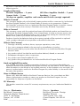
SPECIFICATIONS
MODEL- Type RF 2-Channel X1 X2 X3
Continuous Power Rating (RMS) - Measured at 12.6 Battery Volts
4Ω Load Per Channel 25 Watts x 2 50 Watts x 2 75 Watts x 2
2Ω Load Per Channel 50 Watts x 2 100 Watts x 2 150 Watts x 2
4Ω Load Bridged (mono) 100 Watts x 1 200 Watts x 1 300 Watts x 1
Dimensions:
Height 3.175" (8.07cm) 3.175" (8.07cm) 3.175" (8.07cm)
Width 11.6" (29.46cm) 11.6" (29.46cm) 11.6" (29.46cm)
Length 15.09" (38.33cm) 17.59" (44.68cm) 20.09" (51.03cm)
Battery Fuse Rating (Amp) 30A 50A 80A
(External to Amplifier) Not Supplied Not Supplied Not Supplied
Fuse Type AGU AGU AGU
Signal-to-Noise Ratio >93dB A-weighted
Crossover Slope 48dB/octave
Crossover Frequency All Pass/Low Pass/High Pass/Direct
Crossover Frequency variable from 50Hz to 350Hz
Frequency Response 20Hz to 20kHz ±0.5dB
Bandwidth 20Hz to 22kHz ±3dB
Damping Factor @ 4Ω (at output connector ) >200
Slew Rate 30 Volts/ms
IM Distortion (IHF) <0.05%
Acceptable Signal Voltage Range Variable from 100mV to 6.5V (RCA Input)
Protection NOMAD - Internal analog-computer output protection
circuitry limits power in case of overload. Thermal
switch shuts down the amplifier in case of overheating.
Input Impedance 20k ohms
ACCESSORIES
Connecting PUNCH Capacitors
Maintain the power you need to your Type RF Amplifier.
Color Options
Personalize your Type RF amplifier by changing the top and corner plastics to different colors.
Available through our web site or local retailer.
See our website for other accessories to help you get the most out of your system.
www.rockfordfosgate.com – password TYPERFUSA to access the Type RF page.

13
Ship to: Electronics
Rockford Corporation
Warranty Repair Department
2055 E. 5th Street
Tempe, AZ 85281
RA#: _________________________
Ship to: Speakers
Rockford Acoustic Design
Speaker Returns
2356 Turner Ave. NW
Grand Rapids, MI 49544
RA#: ____________________
LIMITED WARRANTY INFORMATION
Rockford Corporation offers a limited warranty on Rockford Fosgate products on the
following terms:
Length of Warranty
PUNCH Amplifiers – 2 years All Other Amplifier Models – 3 years
Source Units – 1 year Speakers – 1 year
90 days on speaker, amplifier and source unit B-stock (receipt required)
What is Covered
This warranty applies only to Rockford Fosgate products sold to consumers by Authorized
Rockford Fosgate Dealers in the United States of America or its possessions. Product
purchased by consumers from an Authorized Rockford Fosgate Dealer in another country
are covered only by that country’s Distributor and not by Rockford Corporation.
Who is Covered
This warranty covers only the original purchaser of Rockford product purchased from an
Authorized Rockford Fosgate Dealer in the United States. In order to receive service, the
purchaser must provide Rockford with a copy of the receipt stating the customer name,
dealer name, product purchased and date of purchase.
Products found to be defective during the warranty period will be repaired or replaced
(with a product deemed to be equivalent) at Rockford's discretion.
What is Not Covered
1. Damage caused by accident, abuse, improper operations, water, theft
2. Any cost or expense related to the removal or reinstallation of product
3. Service performed by anyone other than Rockford or an Authorized Rockford Fosgate
Service Center
4. Any product which has had the serial number defaced, altered, or removed
5. Subsequent damage to other components
6. Any product purchased outside the U.S.
7. Any product not purchased from an Authorized Rockford Fosgate Dealer
Limit on Implied Warranties
Any implied warranties including warranties of fitness for use and merchantability are
limited in duration to the period of the express warranty set forth above. Some states do not
allow limitations on the length of an implied warranty, so this limitation may not apply. No
person is authorized to assume for Rockford Fosgate any other liability in connection with
the sale of the product.
How to Obtain Service
Please call 1-800-669-9899 for Rockford Customer Service. You must obtain an RA#
(Return Authorization number) to return any product to Rockford Fosgate. You are
responsible for shipment of product to Rockford.
EU Warranty
This product meets the current EU warranty requirements, see your Authorized dealer for
details.

2
Français
INTRODUCTION
TABLE DES MATIÈRES
Cher client,
Toutes nos félicitations pour avoir acheté la meilleure marque d'amplificateurs pour automobile.
Chez Rockford Fosgate nous sommes des mordus de la reproduction musicale à son meilleur. C’est
pourquoi nous sommes heureux que vous ayez choisi notre produit. Des années d’expertise en
ingénierie, de savoir-faire et d’essais poussés nous ont permis de créer une vaste gamme de produits
capables de reproduire toute la clarté et la richesse musicales que vous méritez.
Pour obtenir les meilleurs résultats, nous vous recommandons de faire installer votre nouvel appareil
par un distributeur agréé Rockford Fosgate formé spécialement par notre Institut de formation
technique Rockford (RTTI). Prenez soin de lire la garantie et conservez votre reçu ainsi que
l’emballage d'origine pour usage ultérieur.
Pour monter un excellent système, il ne suffit pas de posséder un super produit et d’assurer une
installation qualifiée compétente. Vous devez veiller à ce que votre installateur utilise des
accessoires d’origine fournis par Connecting Punch. Connecting Punch a tout ce qu’il vous faut, des
câbles RCA aux câbles de haut-parleurs, en passant par les câbles d’alimentation et les connecteurs
de batterie. Insistez pour les avoir! Après tout, votre nouveau système ne mérite rien de moins.
Pour compléter votre nouvelle image Rockford Fosgate, commandez des accessoires Rockford tels
que T-shirts, vestes, chapeaux et lunettes de soleil.
Pour obtenir une brochure gratuite sur les produits Rockford Fosgate et les accessoires Rockford,
appelez aux États-Unis le 480-967-3565 ou faxez au 480-967-8132.
Pour tous les autres pays, appelez le +001-480-967-3565 ou faxez au +001-480-967-8132.
PRATIQUEZ UNE ÉCOUTE SANS RISQUES
MD
Une exposition continue à des niveaux de pression acoustique supérieurs à 100 dB
peut causer une perte d'acuité auditive permanente. Les systèmes audio de forte
puissance pour auto peuvent produire des niveaux de pression acoustique bien au-
delà de 130 dB. Faites preuve de bon sens et pratiquez une écoute sans risques.
NOTE : consultez chaque section pour de plus amples informations.
Si vous avez encore des questions à propos de ce produit, même après avoir lu ce manuel,
contactez votre distributeur agréé Rockford Fosgate. Si vous avez besoin d'aide, appelez-nous au
1-800-669-9899. Veuillez avoir les numéros de modèle et de série, ainsi que la date d'achat de
l'appareil à portée de main lorsque vous appelez.
Le numéro de série est indiqué sur l’extérieur de l’emballage. Veuillez l’inscrire ci-dessous dans
l'espace réservé à cet effet. Il permettra de vérifier votre garantie et de retrouver votre appareil en
cas de vol.
Numéro de série :_______________________________________
Numéro de modèle : ____________________________________
Introduction . . . . . . . . . . . . . . . . . . . . . . . . 2
Consignes de sécurité . . . . . . . . . . . . . . . . . 3
Particularités techniques. . . . . . . . . . . . . . . 4
Installation . . . . . . . . . . . . . . . . . . . . . . . 4-7
Considérations concernant l'installation . 4
Emplacements de montage . . . . . . . . . . 5
Montage de l'amplificateur . . . . . . . . . . 5
Batterie et charge . . . . . . . . . . . . . . . . . 6
Câblage du système. . . . . . . . . . . . . . . . 6
Fonctionnement. . . . . . . . . . . . . . . . . . . 8-10
Choix de couleur . . . . . . . . . . . . . . . . . . . 10
Dépannage . . . . . . . . . . . . . . . . . . . . . . . . 11
Accessoires. . . . . . . . . . . . . . . . . . . . . . . . 12
Caractéristiques . . . . . . . . . . . . . . . . . . . . 12
Garantie limitée . . . . . . . . . . . . . . . . . . . . 13

3
CONSIGNES DE SÉCURITÉ
CONTENU DE L'EMBALLAGE
AVANT DE COMMENCER
Bienvenue à Rockford Fosgate! Ce manuel vise à informer le propriétaire, le vendeur et l’installateur de
l’appareil. Si vous désirez apprendre rapidement comment installer ce produit, consultez la section
Installation du manuel. Reportez-vous à la Table des matières pour d’autres informations. Nous nous
efforçons de faire en sorte que toutes les informations contenues dans ce manuel soient à jour. Mais
comme nous améliorons constamment nos produits, nous nous réservons le droit de modifier ces
informations sans aucun préavis.
Le symbole accompagnant le mot « AVERTISSEMENT » signale à
l'utilisateur la présence d’instructions importantes. Le non-respect
de ces instructions causera des blessures graves ou la mort.
Le symbole accompagnant l’expression «
MISE EN GARDE »
signale à l'utilisateur la présence d’instructions importantes. Le
non-respect de ces instructions peut causer des blessures ou
endommager l’appareil.
MISE EN GARDE : pour éviter des blessures et ne pas endommager l'appareil,
veuillez lire et suivre les instructions du manuel. Notre but est
que ce système vous donne du plaisir et non des maux de tête.
MISE EN GARDE : si vous vous sentez incapable d’installer l’appareil vous-même,
confiez la tâche à un technicien Rockford Fosgate qualifié.
MISE EN GARDE : avant d'entamer l'installation, déconnectez la broche négative (-)
de la batterie pour éviter tout risque de blessures, d’incendie ou
de dommages à l'appareil.
!
!
!
Visitez notre site Web pour obtenir les dernières informations sur tous les produits Rockford.
www.rockfordfosgate.com
Amplificateur à 2 voies, modèle X1, X2 ou
X3
Manuel d'installation et d'utilisation
Kit de matériel de montage
1 clé Allen 1/8 po
1 clé Allen 3/32 po
1 clé Allen 3/16 po
Autocollant RF
Le kit de matériel inclus avec chaque amplificateur contient le matériel de montage nécessaire pour
fixer l'ampli au véhicule et le couvercle au dissipateur thermique.
REMARQUE : reportez-vous à la section des caractéristiques en ce qui concerne les fusibles recommandés.
Le mot de passe pour pénétrer dans la section Type RF est TYPERFUSA
Ce produit est couvert par un ou plusieurs brevets américains, et d'autres sont en instance :
4,467,288 5,673,000 5,751,823 5,936,467 6,097,249

Dessus de
l'ampli
4
Français
INSTALLATION
PARTICULARITÉS TECHNIQUES
CONSIDÉRATIONS CONCERNANT L’INSTALLATION
Voici la liste d’outils requis pour l’installation :
Voltmètre-ohmmètre
Pince à dénuder
Pince à sertir
Coupe-fils
Tournevis à embout cruciforme n
o
2
Clé de borne de batterie
Perceuse à main avec mèches assorties
Tube thermorétrécissable de 1/8 po de
diamètre
Connecteurs assortis
Longueur adéquate — Fil d’alimentation
rouge
1. Écran LCD du DSP - Écran titre lorsque l'amplificateur est allumé.Affiche les menus, sous-menus et
sélections durant le réglage du DSP.
2. Touches à flèche vers le (haut) et vers le (bas) – Font défiler les menus et les sous-menus et
d'effectuer des ajustements durant le paramétrage du DSP.
3. Touche à flèche vers la (gauche) – Recule d'une étape dans les ajustements ou les menus durant
le paramétrage du DSP.
4. Touche à flèche vers la (droite) – Accède aux menus et sous-menus durant le réglage du DSP.
5. Touche de sélection – Permet d'effectuer des sélections dans les menus et les sous-menus, et de
finaliser les ajustements durant le paramétrage du DSP.
6. Dissipateur thermique en aluminium coulé – Le dissipateur thermique en aluminium coulé de
l'amplificateur Power dissipe la chaleur générée par les circuits de l'amplificateur. L'avantage intrinsèque
du moulage est qu'il améliore le refroidissement et les performances thermiques.
7.
Bornes d'alimentation - Les connexions d'alimentation et de masse sont plaquées de platine et peuvent
accueillir des câbles de calibre allant jusqu'à 4 AWG, ce qui permet de maximiser la capacité de courant
d'entrée de l'ampli.
8.
Borne REM – Cette cosse à fourche permet d'allumer et d'éteindre à distance l'amplificateur lorsqu'un
courant de +12 V c.c. est envoyé.
9.
Bornes de haut-parleur – Les connecteurs robustes plaqués de platine des bornes (+ et -) acceptent des
câbles de calibre 8 à 18 AWG. Ces connecteurs plaqués de platine sont à l'épreuve de la corrosion qui
peut nuire au signal.
10.
Prises d'entrée RCA – Les prises RCA de norme industrielle permettent une connexion facile pour les
entrées de signaux. Elles sont plaquées de platine pour résister à la détérioration de signal due à l'effet de
la corrosion.
11. Prises RCA d'extension ampli/de sortie auxiliaires - L'extension ampli/sortie auxiliaire permet
de connecter en guirlande un second ampli en évitant d'acheminer des câbles RCA
supplémentaires de l'avant du véhicule vers l'emplacement de l'ampli arrière.

5
INSTALLA
TION
Cette section traite de points concernant le véhicule dont il faut tenir compte pour l’installation de
votre nouvel ampli. Vous sauverez du temps en planifiant à l’avance la disposition du système et du
câblage. Assurez-vous, entre autres, que chaque composant du système est facilement accessible
pour les réglages.
MISE EN GARDE : si vous vous sentez incapable d’installer l’appareil vous-même,
confiez la tâche à un technicien qualifié.
MISE EN GARDE : avant d'entamer l'installation, déconnectez la broche négative (-)
de la batterie pour éviter tout risque de blessures, d’incendie ou
de dommages à l'appareil.
Avant de commencer l’installation, suivez ces règles toutes simples :
1. Prenez soin de bien lire et comprendre les instructions avant d’installer l’appareil.
2. Par mesure de sécurité, veuillez débrancher le fil négatif de la batterie avant de commencer
l’installation.
3. Pour faciliter le montage, nous vous suggérons de dérouler tous les fils avant d’installer
l’appareil.
4. Acheminez tous les câbles RCA de façon groupée, à l’écart des fils à courant élevé.
5. Utilisez des connecteurs de haute qualité pour assurer une installation fiable et minimiser la
perte de signal ou de puissance.
6. Réfléchissez avant de percer quoique ce soit ! Faites attention de ne pas couper ou percer le
réservoir d’essence, les conduites de carburant, de frein, hydrauliques ou de dépression, ou le
câblage électrique lorsque vous travaillez sur un véhicule.
7. Ne faites jamais passer les fils sous le véhicule. Il vaut mieux les installer à l’intérieur du
véhicule pour assurer une meilleure protection.
8. Évitez de faire passer les fils par dessus ou à travers des bords tranchants. Tout fil acheminé à
travers du métal, un pare-feu en particulier, doit être protégé avec des bagues en caoutchouc ou
plastique.
9. Protégez TOUJOURS la batterie et le circuit électrique des dommages potentiels à l’aide de
fusibles. Installez un porte-fusible et un fusible appropriés sur le câble d’alimentation de +12 V
à moins de 45,7 cm (18”) de la borne de batterie.
10. Préparez la masse du châssis en grattant toute trace de peinture de la surface métallique afin
d’assurer une bonne mise à la masse. Les connexions de masse doivent être aussi courtes que
possible et toujours connectées à du métal soudé à la carrosserie ou au châssis du véhicule.
EMPLACEMENTS DE MONTAGE
L’emplacement de l’ampli influe grandement sur la qualité du son obtenu.
Compartiment moteur
Ne montez jamais cet appareil dans le compartiment moteur. Cela entraînerait l’annulation de la garantie.
Montage dans le coffre (de préférence) et l'habitacle passager
Bien qu'il soit préférable de monter les amplis Type RF sur le plancher du coffre, il est possible de
les monter dans n'importe quel sens. Cela est dû à leur système de refroidissement interne unique
qui utilise des entrées et sorties arrière pour optimiser le mouvement d'air même dans un espace
limité.
MONTAGE DE L'AMPLI
Vous devez enlever le couvercle avant de pouvoir effectuer le montage et le câblage de l'ampli.
Pour ce faire, retirez les quatre (4) vis Allen 3/16 po de chaque coin supérieur de l'ampli. Placez
l'ampli là où il doit être monté et marquez l'emplacement des trous de montage. Lisez la section «
Considérations concernant l'installation » afin d'installer l'appareil en toute sécurité. Câblez et
montez l'ampli, puis replacez le couvercle.
!
!
Longueur adéquate — Fil d’allumage à
distance
Longueur adéquate — Fil de masse noir

6
Français
INSTALLA
TION
BATTERIE ET CHARGE
Les amplificateurs exercent une charge accrue sur la batterie et le système de charge du véhicule. Nous vous
conseillons de vérifier l’état de l’alternateur et de la batterie pour vous assurer que le système électrique puisse
supporter la charge accrue de votre système stéréo. Les systèmes électriques ordinaires en bon état sont
normalement capables de fournir sans problème la charge supplémentaire requise par les amplis Rockford
Fosgate. Toutefois, la durée de vie de la batterie et de l’alternateur peut s’en trouver affectée légèrement. Pour
maximiser la performance de votre ampli, nous vous suggérons d’utiliser une batterie à usage intensif et un
condensateur de stockage d’énergie.
CÂBLAGE DU SYSTÈME
MISE EN GARDE : si vous ne vous sentez pas à l’aise pour effectuer vous-même le câblage de votre
nouvel appareil, veuillez confier l’installation à votre distributeur agréé Rockford
Fosgate.
MISE EN GARDE : avant d'entamer l'installation, déconnectez la broche négative (-) de la batterie
pour éviter tout risque de blessures, d’incendie ou de dommages à l'appareil.
MISE EN GARDE : évitez de faire passer les fils d’alimentation près des câbles d’entrée bas niveau,
de l’antenne, des câbles d'alimentation, des équipements ou faisceaux sensibles.
Les fils d’alimentation transportent un courant élevé et peuvent produire du bruit
dans le système audio.
1. Planifiez l’acheminement des fils. Gardez les câbles RCA ensemble mais en les isolant des câbles
d’alimentation de l’ampli et des autres accessoires automobiles de forte puissance, particulièrement les
moteurs électriques, pour éviter que le signal audio ne subisse d'interférence de bruit provenant de champs
de rayonnement électriques. Si vous faites passer les fils par un pare-feu ou autre barrière métallique,
protégez-les à l’aide de bagues en caoutchouc ou en plastique pour éviter les courts-circuits. Conservez toute
la longueur des fils pour l’instant. Vous l’ajusterez plus tard.
2. Préparez le fil ROUGE (câble d’alimentation) qui devra être relié à l’ampli en dénudant 1/2 po de son
extrémité. Insérez la partie dénudée dans la borne B+, puis fixez le fil en vissant la vis sans tête.
REMARQUE : le câble B+ DOIT comporter un fusible à 18 pouces ou moins de la batterie du véhicule. Installez le
porte-fusible sous le capot et préparez les extrémités de câble tel qu’indiqué ci-dessus. Les
connexions doivent être étanches.
3. Coupez le fil ROUGE (câble d’alimentation) à moins de 18 pouces de la batterie et dénudez 1/2 po de son
extrémité. Épissez le porte-fusible sur le fil d'alimentation à l'aide de connecteurs en ligne appropriés. Utilisez
la section de fil coupée plus tôt et connectez-la à l’autre extrémité du porte-fusible.
4. Dénudez 1/2 po de l’extrémité de batterie du câble d’alimentation et sertissez une grosse cosse à anneau sur
le câble. Connectez la cosse à la borne positive de la batterie. N’installez pas le fusible pour l'instant.
5. Préparez le fil NOIR (câble de mise à la masse) qui devra être relié à l’ampli en dénudant 1/2 po de son
extrémité. Insérez la partie dénudée dans la borne GND, puis fixez le fil en vissant la vis sans tête. Préparez
la masse du châssis en grattant toute trace de peinture de la surface métallique et en nettoyant soigneusement
pour éliminer tout dépôt de saleté et de graisse. Dénudez l’autre extrémité du fil et fixez un connecteur en
anneau. Fixez le câble au châssis à l’aide d’une vis non anodisée et une rondelle en étoile.
6. Préparez le fil d’activation REM qui devra être relié à l’ampli en dénudant 1/2 po de son extrémité. Insérez la
partie dénudée dans la borne REM, puis fixez le fil en vissant la vis sans tête. Connectez l’autre extrémité du
fil REM à une source positive commutée de 12 volts. La tension commutée provient généralement de
l’antenne ou du câble d’accessoires de la source audio. Si la source audio ne comporte pas de telles sorties,
nous recommandons de raccorder un interrupteur mécanique en ligne avec une source de 12 volts pour
activer l’ampli.
7. Montez solidement l’ampli sur le véhicule ou le rack d’ampli. Prenez soin de ne pas le fixer sur des
panneaux en carton ou en plastique. Les vis pourraient en effet se décoller des panneaux sous l’effet des
vibrations de la route ou des arrêts soudains du véhicule.
8. Connectez le signal à l'ampli en branchant les câbles d'entrée RCA dans les prises d'entrée de l'ampli.
9. Connectez les haut-parleurs : dénudez les fils des haut-parleurs de 1/2 po et insérez la partie dénudée dans la
borne du haut-parleur, puis serrez la vis sans tête pour fixer le tout. Veillez à respecter la polarité des haut-
parleurs. NE mettez PAS les fils de haut-parleur à la masse sur le châssis car cela pourrait causer un
fonctionement instable.
10. Effectuez une vérification finale du câblage pour vous assurer que toutes les connexions sont bien mises.
Vérifiez toutes les connexions d’alimentation et de mise à la masse en vue de fils effilochés et de connexions
desserrées pouvant causer des problèmes. Installez le fusible dans le porte-fusible.
!
!
!

7
INSTALLA
TION
REMARQUE : vérifiez les polarités de signal à l’aide des schémas.
MISE EN GARDE : ces amplificateurs ne sont pas recommandés pour des charges
d'impédance inférieures à 2Ω stéréo et 4Ω pontées (mono).
!
Câblage ponté/mono
Câblage à 2 voies
Connexion
d'alimentation

8
Français
FONCTIONNEMENT
CARACTÉRISTIQUES DU DSP
Les amplificateurs de Type RF offrent à l'utilisateur une vaste gamme de
sélections qui lui permet de créer l'environnement sonore qu'il préfère.
Veuillez lire les procédures de réglage avant d'effectuer les ajustements finaux
afin d'obtenir les meilleurs résultats.
FONCTIONS DES BOUTONS DU DSP
Les flèches vers le (haut) et vers le (bas) permettent de parcourir en
amont et en aval les Sélections de menu, les paramètres des Sélections et les Ajustements de paramètres.
La touche de Sélection (au centre) ou la flèche vers la (droite) accèdent aux paramètres individuels des
Sélections de menu.La flèche vers la (gauche) recule d'une étape lorsqu'on se trouve dans les sélections de
paramètre.
Maintenez enfoncée une touche pendant plus d'une (1) seconde lors des réglages pour parcourir rapidement la
sélection dans le sens correspondant à la touche enfoncée.
EXEMPLE : maintenez la flèche vers le (haut) enfoncée dans le paramètre Crossover Freq (Fréq. du filtre) pour
passer rapidement de 50 à 350.
REMARQUE
: les ajustements du paramétrage de l'amplificateur sont sauvegardés lorsque vous quittez le menu
actuel ou l'écran de réglage.Si aucune touche n'est enfoncée 30 secondes après un changement,
vous êtes renvoyé automatiquement à l'écran titre et les changements sont sauvegardés.Pour vous
assurer que les ajustements effectués sont sauvegardés, quittez toujours le menu actuel ou laissez
passer une durée de 30 secondes.Ces paramètres peuvent également être sauvegardés de façon
permanente dans un des cinq (5) emplacements prévus à cet effet à l'aide de la fonction GLOBAL
SAVE (SAUVEGARDE GLOBALE).
MENU ET VALEURS PAR DÉFAUT DU DSP
Message d'accueil – « ROCKFORD FOSGATE TYPE RF DSP » (DSP TYPE RF ROCKFORD FOSGATE) et « PRESS
ANY KEY FOR SETUP MENU » (APPUYEZ SUR UNE TOUCHE QUELCONQUE POUR LE MENU RÉGLAGES) ;
Ceci indique que l'amplificateur est allumé.
L'ordre des menus indiqué est celui que l'on voit lorsque l'amplificateur est allumé pour la première fois.On y
voit les sélections, les paramètres de sélection, l'ajustement des paramètres et les paramètres par défaut.
1. INPUT LEVEL (NIVEAU D' ENTRÉE) – (Paramétrage de la sensibilité à l'entrée de l'amplificateur)
INPUT RANGE (PLAGE D'ENTRÉE) - HI ou LO (HAUT ou BAS) {la valeur par défaut est HI}
Le paramètre LO est réservé à une sortie d'unité source inférieure ou égale à 1,0 volt.Le paramètre HI est
réservé à une sortie d'unité source supérieure ou égale à 1,1 volts.
GAIN LEVEL (NIVEAU DE GAIN) - 0-30 {la valeur par défaut est 30}
2.
GLOBAL SAVE (SAUVEGARDE GLOBALE) - (Permet de sauvegarder jusqu'à 5 paramètres entiers dans une
mémoire non-volatile)
PRESET SELECT (CHOIX DE PRÉSÉLECTION) - 1-5 {la valeur par défaut est Ø}
Sélectionne la présélection en mémoire à utiliser.
PRESET PERFORM (PERFORMANCE DE PRÉSÉLECTION) - PROTECT, SAVE, LOAD ou RESTORE
(PROTÉGER, SAUVEGARDER, CHARGER ou RESTAURER) {la valeur par défaut est PROTECT}
Sélectionne la fonction à activer pour la présélection choisie.PROTECT :désactive toutes les actions de la
présélection choisie jusqu'à modification à l'aide des flèches vers le haut/bas.SAVE : sauvegarde les
paramètres actuels de l'amplificateur dans la présélection choisie.LOAD : charge les paramètres de la
présélection choisie dans l'amplificateur.RESTORE : restaure tous les paramètres de la présélection choisie
aux valeurs par défaut du fabricant.
REMARQUE : attendez toujours que l'affichage indique que la sauvegarde est achevée avant d'éteindre l'ampli.
3.
TIME DELAY (DÉLAI DE TEMPORISATION) – (Impose un délai au signal de sortie de la voie droite, gauche
ou les deux)
SIGNAL SELECT (CHOIX DE SIGNAL) - L CHAN, R CHAN ou L+R CHAN (VOIE G, VOIE D ou VOIE G+D)
Sélectionne la voie de sortie pour le délai de signal.
DELAY ADJUST (RÉGLAGE DU DÉLAI) - 0-500 (réglage par incréments de 20 microsecondes) {la valeur par
défaut est Ø}
Ce paramètre peut être ajusté individuellement pour chaque sélection de signal avec un délai de signal de
500 microsecondes maximum {0-10 millisecondes}. Les paramètres effectués dans la sélection L-CHAN ou R
CHAN s'additionnent au paramètre effectué dans la sélection L+R CHAN. Le réglage des délais des voies L
ou R permet à l'utilisateur de décentrer ou de centrer l'image stéréo comme il le désire, alors que le
paramètre de délai de la voie G+D permet de balancer le délai de signal relatif entre deux (2) amplificateurs
La pagina sta caricando ...
La pagina sta caricando ...
La pagina sta caricando ...
La pagina sta caricando ...
La pagina sta caricando ...
La pagina sta caricando ...
La pagina sta caricando ...
La pagina sta caricando ...
La pagina sta caricando ...
La pagina sta caricando ...
La pagina sta caricando ...
La pagina sta caricando ...
La pagina sta caricando ...
La pagina sta caricando ...
La pagina sta caricando ...
La pagina sta caricando ...
La pagina sta caricando ...
La pagina sta caricando ...
La pagina sta caricando ...
La pagina sta caricando ...
La pagina sta caricando ...
La pagina sta caricando ...
La pagina sta caricando ...
La pagina sta caricando ...
La pagina sta caricando ...
La pagina sta caricando ...
La pagina sta caricando ...
La pagina sta caricando ...
La pagina sta caricando ...
La pagina sta caricando ...
La pagina sta caricando ...
La pagina sta caricando ...
La pagina sta caricando ...
La pagina sta caricando ...
La pagina sta caricando ...
La pagina sta caricando ...
La pagina sta caricando ...
La pagina sta caricando ...
La pagina sta caricando ...
La pagina sta caricando ...
La pagina sta caricando ...
La pagina sta caricando ...
La pagina sta caricando ...
La pagina sta caricando ...
-
 1
1
-
 2
2
-
 3
3
-
 4
4
-
 5
5
-
 6
6
-
 7
7
-
 8
8
-
 9
9
-
 10
10
-
 11
11
-
 12
12
-
 13
13
-
 14
14
-
 15
15
-
 16
16
-
 17
17
-
 18
18
-
 19
19
-
 20
20
-
 21
21
-
 22
22
-
 23
23
-
 24
24
-
 25
25
-
 26
26
-
 27
27
-
 28
28
-
 29
29
-
 30
30
-
 31
31
-
 32
32
-
 33
33
-
 34
34
-
 35
35
-
 36
36
-
 37
37
-
 38
38
-
 39
39
-
 40
40
-
 41
41
-
 42
42
-
 43
43
-
 44
44
-
 45
45
-
 46
46
-
 47
47
-
 48
48
-
 49
49
-
 50
50
-
 51
51
-
 52
52
-
 53
53
-
 54
54
-
 55
55
-
 56
56
-
 57
57
-
 58
58
-
 59
59
-
 60
60
-
 61
61
-
 62
62
-
 63
63
-
 64
64


Rockford Fosgate Car Amplifier X1 Manuale utente
- Tipo
- Manuale utente
in altre lingue
Documenti correlati
-
 Rockford Fosgate 45.2 Manuale utente
-
 Rockford Fosgate Power 351M Manuale utente
-
 Rockford Fosgate Power 250M Istruzioni per l'uso
-
 Rockford Fosgate RFT3081A Manuale utente
-
 Rockford Fosgate PUNCH 301M Installation & Operation Manual
-
 Rockford Fosgate 4.6 Istruzioni per l'uso
-
 Rockford Fosgate Punch 100z2 Guida d'installazione


