
Installation Instructions
PanelView 550/600 Touch Screen Terminals
English........................................................................................... Page 1
Terminaux PanelView 550/600 á écran tactile
Français....................................................................................... Page 13
PanelView 550/600 Touchscreen-Terminals
Deutsch ....................................................................................... Seite 25
Terminales de Pantalla Táctil PanelView 550/600
Español..................................................................................... Página 37
Terminali PanelView 550/600 a schermo tattile
Italiano.......................................................................................Pagina 49


41061-109-01(B)
Installation Instructions
PanelView 550/600 Touch Screen Terminals
This document describes how to mount a PanelView 550/600 touch screen
terminal in a panel or enclosure and apply power.
• hazardous locations
• European Union Directive Compliance
• wiring and safety guidelines
• enclosures
• required tools
• mounting dimensions
• clearances
• installing the terminal in a panel
• installing the memory card retainer
• connecting DC power
For more information on the PanelView 550/600 Operator Terminals, refer to
Publication 2711-6.1.
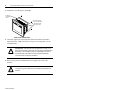
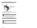
Hazardous Locations
See nameplate label on terminal for certification details.
The PanelView 550 touch screen terminals have an operating temperature code of
T2 (maximum operating temperature of 300
° C or 572° F). Do not install the
terminals in environments where atmospheric gases have ignition temperatures
less than 300
° C (572° F).
The PanelView 600 touch screen terminals have an operating temperature code of
T4 (maximum operating temperature of 135
° C or 275° F). Do not install the
terminals in environments where atmospheric gases have ignition temperatures
less than 135
° C (275° F).
!
ATTENTION: In Class 1, Div 2 and Class 1, Zone 2 hazardous locations,
the PanelView 550/600 terminal must be wired per the National Electric
Code and/or Canadian Electric Code as it applies to hazardous locations.
Peripheral equipment must also be suitable for the location in which it is
installed.

2 PanelView 550/600 Touch Screen Terminals
41061-109-01(B)
European Union Directive Compliance
If a PanelView 550/600 touch screen terminal is installed within the European
Union or EFTA regions and has a CE mark, the following regulations apply.
This apparatus is tested to meet directives:
• EMC Directive 89/336/EEC Electromagnetic Compatibility (EMC) and
ammending directives 92/31/EEC, 93/68/EEC
• Low Voltage Directive 73/23/EEC and amending directive 93/68/EEC
Using the following standards, in whole or in part:
• EN 50081-2:1993 EMC - Generic Emission Standard, Part 2 - Industrial
Environment
• EN 50082-2:1995 EMC - Generic Immunity Standard, Part 2 - Industrial
Environment
• EN 61131-2:1995 EMC - Programmable Controllers - Equipment
Requirements and Tests
The product described is intended for use in an industrial environment.
Intended Use of Product
According to these Standards, the factor which determines, for EMC purposes,
whether an apparatus is deemed to be “Industrial” or “Residential, commercial
and light industrial”, is given in Clause 1 of EN50081-2 as follows:
Apparatus covered by this standard is not intended for connection to a public
mains network but is intended to be connected to a power network supplied
from a high- or medium-voltage transformer dedicated for the supply of an
installation feeding a manufacturing or similar plant.
The PanelView 550/600 touch screen terminal is intended for use solely in an
industrial environment as defined above. When installed in Europe, any other
application is in contravention of European Union Directives, and a breach of
these laws.

PanelView 550/600 Touch Screen Terminals 3
41061-109-01(B)
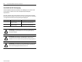
Wiring and Safety Guidelines
Install the PanelView 550/600 touch screen terminal using publication 70E,
Electrical Safety Requirements for Employee Workplaces. In addition to the
NFPA general guidelines, follow these recommendations:
• Route incoming power to the PanelView 550/600 terminal by a separate path
from the communications cable.
• Where power and communication lines must cross, they should cross at right
angles. Communications lines can be installed in the same conduit as low
level DC I/O lines (less than 10 Volts).
• Grounding minimizes noise from Electromagnetic Interference (EMI) and is a
safety measure in electrical installations. To avoid EMI, shield and ground
cables appropriately.
• A source for grounding recommendations is the National Electrical Code
published by the National Fire Protection Association of Boston.
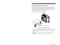
Enclosures
Mount the PanelView 550/600 touch screen terminal in a panel or enclosure to
protect the internal circuitry. The terminal meets NEMA Type 12/13 and 4X
(indoor use) ratings only when properly mounted in a panel or enclosure with the
equivalent rating.
Allow enough space within the enclosure for adequate ventilation. Consider heat
produced by other devices in the enclosure. The ambient temperature around the:
• PV550 terminal must be between 0° and 55°C (32° and 131°F).
• PV600 terminal must be between 0° and 50°C (32° and 122°F).
Make provisions for accessing the back panel of the terminal for wiring,
maintenance, installing a memory card, and troubleshooting.

4 PanelView 550/600 Touch Screen Terminals
41061-109-01(B)
Required Tools
Other than the tools required to make the panel cutout, the tools required for
installation are:
• 7mm (M4) deep well socket wrench or nut driver
• small slotted screwdriver
• torque wrench (in. / lbs).
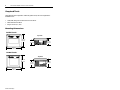
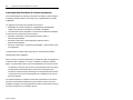
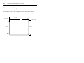
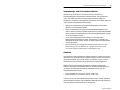
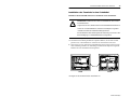
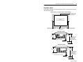
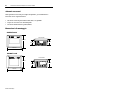
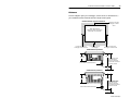
Mounting Dimensions
185 mm
(7.28 in)
152 mm
(6.00 in)
Top View
82 mm
(3.20 in)
Top View
64 mm
(2.54 in)
185 mm
(7.28 in)
152 mm
(6.00 in)
PV550 Touch
PV600 Touch
79 mm
(3.12 in)
96 mm
(3.80 in)

PanelView 550/600 Touch Screen Terminals 5
41061-109-01(B)
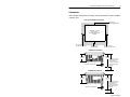
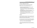
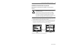
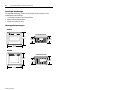
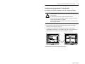
Clearances
Allow adequate clearances for mounting, air flow, maintenance, and for installing
a memory card.
TERMINAL CUTOUT
Use Full Size
Template shipped with
Ter mi nal
Side, Top and Bottom Clearances
109 mm
(4.30 in)
188 mm (7.4 in.) is
required to insert
and remove a
memory card with
the memory card
retainer.
64 mm
(2.54 in)
38 mm (1.5 in.)
for Mounting
25 mm (1 in.) for
Mounting and Air Flow
25 mm (1 in.) for
Mounting and Air Flow
25 mm (1 in.)
for Mounting/Air Flow
Memory Card Retainer
132 mm
(5.21 in)
211 mm (8.30 in.) is
required to insert
and remove a
memory card with
the memory card
retainer.
79 mm
(3.12 in)
Memory Card Retainer
PV550 Back Clearance
PV600 Back Clearance
Card
Card

6 PanelView 550/600 Touch Screen Terminals
41061-109-01(B)
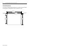
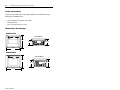
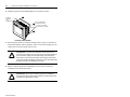
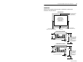
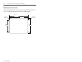
Cutout Dimensions
Use the full size template shipped with the PV550 or PV600 terminal to mark the
cutout dimensions. The figure below shows a reduced size cutout.
4.8 mm dia.
(0.188 in.)
98 mm
(3.86 in)
125 mm
(4.91 in)
158 mm
(6.20 in)
165 mm
(6.49 in)
R 1.8 mm dia.
(0.07 in.)

PanelView 550/600 Touch Screen Terminals 7
41061-109-01(B)
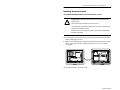
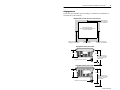
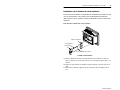
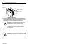
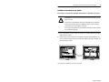
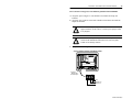
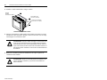
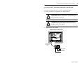
Installing Terminal in Panel
To install the PV550/PV600 touch screen terminal in a panel:
1.
Cut an opening in the panel using the panel cutout provided with the terminal.
Remove sharp edges or burrs.
2. Make sure the sealing gasket is properly positioned on the terminal (as shown
below). This gasket forms a compression type seal. Do not use sealing
compounds.
3. Place the terminal in the panel cutout.
!
ATTENTION: Disconnect all electrical power from the panel before
making cutout.
Make sure the area around the panel cutout is clear.
Take precautions so that metal cuttings do not enter any components that
may already be installed in panel.
Failure to follow this warning may result in personal injury or damage to
the panel components.
Sealing
Gasket
PV550
PV600

8 PanelView 550/600 Touch Screen Terminals
41061-109-01(B)
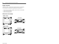
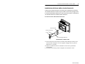
4. Install the 4 self-locking nuts, hand tight.
5. Alternately tighten the self-locking nuts until the terminal is held firmly
against the panel. Tighten the nuts to a torque of 10 inch-pounds. Do not
overtighten nuts.
6. Remove the protective installation label covering the top vents of the
terminal.
!
ATTENTION: Mounting nuts must be tightened to a torque of 10
inch-pounds to provide a proper seal and to prevent potential damage to
the terminal. Allen-Bradley assumes no responsibility for water or
chemical damage to the terminal or other equipment within the
enclosure because of improper installation.
!
ATTENTION: Failure to remove the protective installation label
covering the top vents could result in overheating and damage to the
terminal.
Protective
Installation
Label
Self-Locking Nuts
(4 used, 8 provided)
Mounting Studs
(2 left / 2 right)
PV600 shown, PV550 similar

PanelView 550/600 Touch Screen Terminals 9
41061-109-01(B)
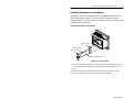
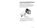
Installing the Memory Card Retainer
The memory card retainer is required for UL508 installations where a memory
card is inserted in the card slot. The retainer protects against Electrostatic
Discharge (ESD) up to 15KV and prevents accidental removal of a memory card
in high vibration environments.
To attach the memory card retainer:
1.
Secure the base of the retainer over the existing memory card slot using the
two screws provided. Tighten screws to a torque of 6 to 8 inch lbs (.7 to .9
N•m).
2. Insert the memory card and install the retainer until it is properly seated.
3. To remove the retainer, press the tabs on each side and pull.
Retainer Base
Memory Card
Retainer
Base Mounting Screws
PV500 shown, PV600 similar

10 PanelView 550/600 Touch Screen Terminals
41061-109-01(B)
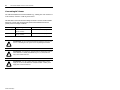
Connecting DC Power
All of the PV550/600 touch screen terminals (e.g., Catalog No. 2711-T5A1L1 or
2711-T6C8L1) connect to a 24V dc power source.
The table below shows the electrical ratings for the DC versions of the terminals.
Electronic circuitry and an internal fuse protect the terminals from reverse
polarity and over-voltage conditions.
Terminal Type Supply Voltage Power Consumption
PV550 Touch 18 to 32V dc,
(24V dc nominal)
18 Watts max. (0.75 Amps @ 24V dc)
PV600 Touch 18 to 32V dc,
(24V dc nominal)
17 Watts max. (0.71 Amps @ 24V dc)
!
ATTENTION: Do not connect the PanelView terminal to an AC power
source. Connecting to an AC power source may damage the terminal.
!
ATTENTION: The PanelView 550/600 terminal is designed for safe use
when installed in a suitably rated NEMA Type 12, 13, 4X (indoor use
only), IP54 or IP65 enclosure.
!
ATTENTION: Use only a Safety Extra Low-Voltage (SELV) power
supply as a source for the PanelView 550/600 terminal. A SELV power
supply does not exceed 42.4V dc.

PanelView 550/600 Touch Screen Terminals 11
41061-109-01(B)
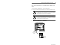
To connect DC power to the PV550/PV600 touch screen terminal:
1.
Secure the DC power wires to the terminal block screws.
2. Secure the Earth Ground wire to the correct terminal block screw.
3. Apply 24V dc power to the terminal.
!
ATTENTION: Explosion Hazard - Do not connect or disconnect
equipment while circuit is live unless area is known to be non–
hazardous.
!
ATTENTION: Do not apply power to the terminal until all wiring
connections have been made. Failure to do so may result in electrical
shock.
+
Earth Ground
DC Negative
DC Positive
Power
Terminal
Block (fixed)
PV550 shown, PV600 similar

12 PanelView 550/600 Touch Screen Terminals
41061-109-01(B)

41061-109-01(B)
Notice d’installation
Terminaux PanelView 550/600 à écran tactile
Ce document explique comment monter le terminal PanelView 550/600 à écran
tactile dans un panneau ou une armoire et le mettre sous tension.
• emplacements dangereux
• conformité aux Directives de l’Union européenne
• conseils de câblage et de sécurité
• armoires
• outillage utilisé
• dimensions de montage
• dégagements
• installation du terminal dans un panneau
• installation de la fixation de carte mémoire
• connexion de l’alimentation c.c.
Pour plus d’informations sur les terminaux opérateurs PanelView 550/600, se
reporter à la Publication 2711-6.1FR.
Emplacements dangereux
Voir sur la plaque d’identification du terminal les informations concernant sa
conformité aux différents standards.
Les terminaux PanelView 550 à écran tactile ont un code de température de
fonctionnement de T2 (température de fonctionnement maximale de 300 °C ou
572 °=F). Ne pas les installer dans des environnements où les gaz atmosphériques
ont une température d’inflammation inférieure à 300 °C (572 °F).
Les terminaux PanelView 600 à écran tactile ont un code de température de
fonctionnement de T4 (température de fonctionnement maximale de 135 °C ou
275°F). Ne pas les installer dans des environnements où les gaz atmosphériques
ont une température d’inflammation inférieure à 135 °C (275 °F).
!
ATTENTION: Dans des emplacements dangereux, Classe I, Division 2,
le terminal PanelView 550/600 doit être câblé suivant le Code Electrique
National et/ou le Code Electrique Canadien tels qu’ils s’appliquent aux
emplacements dangereux. Les périphériques utilisés doivent également être
conçus pour fonctionner dans de tels emplacements.

14 Terminaux PanelView 550/600 à écran tactile
41061-109-01(B)
Conformité aux Directives de I’Union européenne
Si un terminal PanelView 550/600 à écran tactile est installé au sein de l’Espace
économique européen (EEE) et a la marque CE, les réglementations suivantes
s’appliquent.
Ces appareils ont été testés pour répondre aux Directives:
• 89/336/EEC du Comité en matière de compatibilité électromagnétique
(CEM) et aux directives modificatives, 92/31/EEC, 93/68/EEC
• Directive basse tension 73/23/EEC et aux directives modificative 32/68/EE
au moyen de tout ou partie des normes suivantes :
• EN 50081-2:1993 CEM - Norme générique émission, Partie 2 -
Environnement industriel
• EN 50082-2:1995 CEM - Norme générique immunité, Partie 2 -
Environnement industriel
• EN 61131-2:1995 CEM - Automates programmables - Spécifications et tests
de l’équipement
Le produit décrit est destiné à être utilisé dans un environnement industriel.
Usage prévu pour l’appareil
Selon ces normes, le facteur qui détermine, en matière de CEM, si un appareil est
considéré comme “industriel” ou comme “résidentiel, commercial, industrie
légère”, est précisé dans l’article 1 de la norme EN50081-2 de la façon suivante :
Les appareils couverts par cette norme ne sont pas destinés à être raccordés à
un réseau public d’alimentation basse tension mais sont destinés à être
raccordés à un réseau d’énergie alimenté par un transformateur haute tension
ou moyenne tension réservé à l’alimentation de l’installation d’une usine ou
d’un local analogue.
Les terminaux PanelView 550/600 à écran tactile sont destinés à n’être utilisés
que dans un environnement industriel tel qu’il est décrit ci-dessus. Pour une
installation en Europe, toute autre application se ferait en violation des Directives
de l’Union européenne, et en infraction des lois.

Terminaux PanelView 550/600 à écran tactile 15
41061-109-01(B)
Conseils de câblage et de sécurité
Pour installer le terminal PanelView 550/600 à écran tactile, utiliser la
publication NFPA 70E, “Electrical Safety Requirements for Employee
Workplaces”. Suivre en outre les conseils généraux suivants :
• faire passer les fils de l’alimentation secteur du terminal par un chemin
différent de celui du câble de communication.
• lorsque les lignes d’alimentation et de communication se croisent, leur
intersection doit se faire à angle droit. Les lignes de communication peuvent
être installées dans le même conduit que les lignes d’E/S c.c. basse tension
(moins de 10 volts).
• la mise à la masse minimise les effets parasites des interférences
électromagnétiques (EMI) et est une mesure de sécurité pour toute installation
électrique. Pour éviter les problèmes causés par les EMI, tous les câbles
doivent être blindés et mis à la masse à une extrémité.
• une source intéressante de conseils pour la mise à la masse est le “National
Electrical Code” publié par la “National Fire Protection Association” de
Boston, Massachusetts (USA).
Armoires
Monter le terminal PanelView 550/600 à écran tactile sur un panneau ou dans une
armoire pour protéger les circuits internes. Le terminal ne répond aux normes
NEMA Type 12/13 et Type 4X (utilisation en intérieur) que s’il est monté sur un
panneau ou dans une armoire aux normes équivalentes.
Dans une armoire, laisser assez d’espace pour que la ventilation soit suffisante.
Pour certaines applications, on peut avoir à considérer la chaleur dégagée par les
autres appareils sur le panneau. La température ambiante doit être maintenue :
• entre 0° C et 55° C (32° et 131° F) pour le terminal PV500.
• entre 0° C et 50° C (32° et 122° F) pour le terminal PV600.
S’assurer qu’une place suffisante est laissée pour l’accès à la face arrière du
terminal pour le câblage, l’entretien de routine, l’insertion d’une carte mémoire et
le dépannage.

16 Terminaux PanelView 550/600 à écran tactile
41061-109-01(B)
Outils nécessaires
A part ceux nécessaires pour la découpe du panneau, les outils dont on aura
besoin pour l’installation sont :
• une clé à douille ou à pipe de 7 mm (M4)
• un petit tournevis
• une clé dynamométrique (m-kgf).
Dimensions de montage
183 mm
152 mm
Vue du dessus
82 mm64 mm
Vue du dessus
185 mm
152 mm
PV600 tactile
79 mm
96 mm
PV550 tactile

Terminaux PanelView 550/600 à écran tactile 17
41061-109-01(B)
Dégagements
Laisser une place suffisante pour le montage, la ventilation, la maintenance et
l’insertion de la carte mémoire.
Laisser 38 mm
pour le montage
Laisser 25 mm pour le
montage et la ventilation
Laisser 25 mm pour le
montage et la ventilation
Laisser 25 mm
pour le montage
et la ventilation
Découpe du terminal
Utiliser le modèle grandeur nature
livré avec le terminal
Dégagements du côté, du dessus et du dessous
109 mm
64 mm
Fixation de carte mémoire
132 mm
79 mm
Il faut environ 19 cm
pour insérer ou retirer
une carte mémoire
avec fixation.
Dégagement arrière pour PV600
Dégagement arrière pour PV550
carte
Il faut environ 21 cm
pour insérer ou retirer
une carte mémoire
avec fixation.
Fixation de carte mémoire
carte

18 Terminaux PanelView 550/600 à écran tactile
41061-109-01(B)
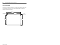
Dimensions de découpe
Utiliser le gabarit de découpe grandeur nature livré avec le terminal pour marquer
les dimensions de la découpe. La figure ci-dessous est un modèle réduit de
découpe.
4.8 mm dia.
98 mm 125 mm
158 mm
165 mm
R 1,8 mm dia.
La pagina si sta caricando...
La pagina si sta caricando...
La pagina si sta caricando...
La pagina si sta caricando...
La pagina si sta caricando...
La pagina si sta caricando...
La pagina si sta caricando...
La pagina si sta caricando...
La pagina si sta caricando...
La pagina si sta caricando...
La pagina si sta caricando...
La pagina si sta caricando...
La pagina si sta caricando...
La pagina si sta caricando...
La pagina si sta caricando...
La pagina si sta caricando...
La pagina si sta caricando...
La pagina si sta caricando...
La pagina si sta caricando...
La pagina si sta caricando...
La pagina si sta caricando...
La pagina si sta caricando...
La pagina si sta caricando...
La pagina si sta caricando...
La pagina si sta caricando...
La pagina si sta caricando...
La pagina si sta caricando...
La pagina si sta caricando...
La pagina si sta caricando...
La pagina si sta caricando...
La pagina si sta caricando...
La pagina si sta caricando...
La pagina si sta caricando...
La pagina si sta caricando...
La pagina si sta caricando...
La pagina si sta caricando...
La pagina si sta caricando...
La pagina si sta caricando...
La pagina si sta caricando...
La pagina si sta caricando...
La pagina si sta caricando...
La pagina si sta caricando...
La pagina si sta caricando...
La pagina si sta caricando...
-
 1
1
-
 2
2
-
 3
3
-
 4
4
-
 5
5
-
 6
6
-
 7
7
-
 8
8
-
 9
9
-
 10
10
-
 11
11
-
 12
12
-
 13
13
-
 14
14
-
 15
15
-
 16
16
-
 17
17
-
 18
18
-
 19
19
-
 20
20
-
 21
21
-
 22
22
-
 23
23
-
 24
24
-
 25
25
-
 26
26
-
 27
27
-
 28
28
-
 29
29
-
 30
30
-
 31
31
-
 32
32
-
 33
33
-
 34
34
-
 35
35
-
 36
36
-
 37
37
-
 38
38
-
 39
39
-
 40
40
-
 41
41
-
 42
42
-
 43
43
-
 44
44
-
 45
45
-
 46
46
-
 47
47
-
 48
48
-
 49
49
-
 50
50
-
 51
51
-
 52
52
-
 53
53
-
 54
54
-
 55
55
-
 56
56
-
 57
57
-
 58
58
-
 59
59
-
 60
60
-
 61
61
-
 62
62
-
 63
63
-
 64
64


Allen-Bradley PanelView 550 Installation Instructions Manual
- Tipo
- Installation Instructions Manual
- Questo manuale è adatto anche per
in altre lingue
- English: Allen-Bradley PanelView 550
- français: Allen-Bradley PanelView 550
- español: Allen-Bradley PanelView 550
- Deutsch: Allen-Bradley PanelView 550
Documenti correlati


Altri documenti
-
 Rockwell Automation 2711P-RC3 Installation Instructions Manual
-
CAME SURFACE-MOUNTED BOX Guida d'installazione
-
Rockwell A-B Quality 6185-F Quick Start
-
Roland Fantom-X6 Manuale utente
-
Aldes Dee Fly Cube 550+ Installation Instructions Manual
-
Mettler Toledo IND780 Guida d'installazione
-
KYOCERA KM-3060 Manuale utente
-
Yamaha RXV461BL Manuale utente
