
Hardware Review
A
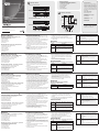
CE610L (Local Unit) Front and Rear View
1. LEDs (Power, Link, USB and Video)
2. Firmware Upgrade Port
3. Unit to Unit Port
4. DVI-D Input Port
5. USB Type B Input
6. Power Jack
CE610R (Remote Unit) Front and Rear View
1. LEDs (Power, Link, USB and Video)
2. Firmware Upgrade Port
3. Unit to Unit Port
4. DVI-D Output Port
5. USB Type A Ports
6. Power Jack
Hardware
A
CE610L (unità locale) – lato anteriore e posteriore
1. LED (alimentazione, link, USB e video)
2. Porta per l’aggiornamento del rmware
3. Porta da unità a unità
4. Porta ingresso DVI-D
5. Porta USB di tipo B
6. Presa d’alimentazione
CE610R (unità remota) – lato anteriore e posteriore
1. LED (alimentazione, link, USB e video)
2. Porta per l’aggiornamento del rmware
3. Porta da unità a unità
4. Porta uscita DVI-D
5. Porte USB di tipo A
6. Presa d’alimentazione
Presentación del hardware
A
Unidad local CE610L – Vistas anterior y posterior
1. Indicadores (Alimentación, Conexión, USB e Imagen)
2. Puerto para actualizaciones del rmware
3. Puerto de unidad a unidad
4. Puerto de entrada DVI-D
5. Entrada USB de tipo B
6. Entrada de alimentación
Unidad remota CE610R – Vistas anterior y posterior
1. Indicadores (Alimentación, Conexión, USB e Imagen)
2. Puerto para actualizaciones del rmware
3. Puerto de unidad a unidad
4. Puerto de salida DVI-D
5. Puertos USB de tipo A
6. Entrada de alimentación
Hardwareübersicht
A
CE610L (lokales Gerät) Vorder- und Rückseite
1. LED-Anzeigen (Betrieb, Verbindung, USB und Bild)
2. Port zur Firmwareaktualisierung
3. Buchse für Direktverbindung Gerät auf Gerät
4. DVI-D-Eingang
5. USB-Eingang, Typ B
6. Stromeingangsbuchse
CE610R (Gerät für Gegenstelle) Vorder- und Rückseite
1. LED-Anzeigen (Betrieb, Verbindung, USB und Bild)
2. Port zur Firmwareaktualisierung
3. Buchse für Direktverbindung Gerät auf Gerät
4. DVI-D-Ausgang
5. USB-Ports, Typ A
6. Stromeingangsbuchse
Description de l’appareil
A
CE610L (unité locale) – Vue avant et arrière
1. Voyants (Alimentation, Liaison, USB et Vidéo)
2. Port de mise à jour du microprogramme
3. Port de connexion d'unité à unité
4. Port d’entrée DVI-D
5. Entrée USB de type B
6. Prise d’alimentation
CE610R (unité distante) – Vue avant et arrière
1. Voyants (Alimentation, Liaison, USB et Vidéo)
2. Port de mise à jour du microprogramme
3. Port de connexion d'unité à unité
4. Port de sortie DVI-D
5. Ports USB de type A
6. Prise d’alimentation
Hardware Installation
B
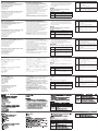
1. Connect the USB cable to the USB Type B on the Local
Unit (CE610). Plug the other end of the cable into a USB
Type A port on the local computer.
2. Connect the DVI-D cable to the DVI In port located on the
Local Unit (CE610L). Plug the other end of the cable into
the DVI input port on the local computer.
3. Plug either end of the Cat 5e cable into the CE610's
Unit to Unit RJ-45 port. Plug the other end of the Cat 5e
cable into the Unit to Unit RJ-45 port of the Remote Unit
(CE610R).
4. Plug the power adapter cable into the power jack on the
CE610L.
5. Use a DVI cable to connect the DVI Output port on the
Remote Unit (CE610R) to your monitor.
Installazione dell’hardware
B
1. Collegare il cavo USB alla porta USB di tipo B sull’unità
locale (CE610) e l’altra estremità alla porta USB di tipo A
del computer locale.
2. Collegare il cavo DVI-D alla porta d’ingresso DVI sull’unità
locale (CE610L) e l’altra estremità alla porta d’ingresso
DVI del computer locale.
3. Inserire un’estremità del cavo Cat 5e nella porta RJ-45 da
unità a unità del CE610. Inserire l’altra estremità del cavo
Cat 5e nella porta RJ-45 da unità a unità dell’unità remota
(CE610R).
4. Inserire il cavo dell’alimentatore nella presa
d’alimentazione del CE610L.
5. Collegare con un cavo DVI l’uscita DVI sull’unità remota
(CE610R) al monitor.
Instalar el hardware
B
1. Conecte el cable USB a la toma USB de tipo B de la
unidad local (CE610). Enchufe el otro extremo del cable
en el puerto de tipo A de la computadora local.
2. Conecte el cable DVI-D a la toma DVI de la unidad local
(CE610L). Enchufe el otro extremo del cable en el puerto
DVI de la computadora local.
3. Conecte un extremo del cable de Cat. 5e al puerto Unit to
Unit RJ-45 de la unidad CE610. Conecte el otro extremo
del cable de Cat. 5e al puerto Unit to Unit RJ-45 de la
unidad remota (CE610R).
4. Conecte el cable del adaptador de alimentación a la
entrada de alimentación del CE610L.
5. Conecte la salida DVI de la unidad remota (CE610R) al
monitor. Para ello, emplee un cable DVI.
Hardware installieren
B
1. Verbinden Sie das USB-Kabel mit der USB-Buchse Typ B am
lokalen Gerät (CE610). Verbinden Sie das andere Ende des
Kabels mit der USB-Buchse Typ A des lokalen Computers.
2. Verbinden Sie das DVI-D-Kabel mit der DVI-Eingangsbuchse
am lokalen Gerät (CE610L). Verbinden Sie das andere Ende
des Kabels mit dem DVI-Eingang des lokalen Computers.
3. Verbinden Sie ein beliebiges Ende des Kat. 5e-Kabels mit
dem Anschluss Unit to Unit RJ-45 des CE610. Verbinden Sie
das andere Ende des Kat. 5e-Kabels mit dem Anschluss Unit
to Unit RJ-45 des Gerätes der Gegenstelle (CE610R).
4. Verbinden Sie das Kabel des Netzteils mit der
Stromeingangsbuchse am CE610L.
5. Verbinden Sie den DVI-Ausgang des Gerätes der Gegenstelle
(CE610R) mit Ihrem Monitor. Verwenden Sie dazu ein DVI-
Kabel.
Installation du matériel
B
1. Connectez le câble USB au port USB de type B de l’unité
locale (CE610). Branchez l’autre extrémité du câble dans un
port USB de type A de l’ordinateur local.
2. Connectez le câble DVI-D au port d’entrée DVI de l’unité
locale (CE610L). Branchez l’autre extrémité du câble dans
un port d’entrée DVI de l’ordinateur local.
3. Branchez une extrémité du câble de catégorie 5e sur le
port RJ-45 de connexion d’unité à unité de l’unité CE610.
Branchez l'autre extrémité du câble de catégorie 5e sur le
port RJ-45 de connexion d’unité à unité de l’unité distante
(CE610R).
4. Branchez le câble de l’adaptateur secteur dans la prise
d’alimentation de l’unité CE610L.
5. Utilisez un câble DVI pour connecter le port de sortie DVI de
l’unité distante (CE610R) à votre moniteur.
6. Plug the cables from the remote USB devices (mouse,
keyboard and any device that supports USB 2.0 ) into
their USB ports on the Remote Unit CE610R.
7. Plug the second power adapter cable into the power jack
on the CE610R.
Operation
CE610L (Local Unit) and CE610R (Remote Unit)
LED Indication
Power
(Green)
Lights steadily to indicate that the system is
receiving power.
Link
(Green)
Lights steadily to indicate that the connection
to the Local and Remote units is ok.
Flashes when there is a problem with the
connection.
6. Inserire i cavi provenienti dai dispositivi USB remoti
(mouse, tastiera e qualsiasi dispositivo USB 2.0) nelle
relative porte sull’unità remota (CE610R).
7. Inserire il cavo del secondo alimentatore nella presa
d’alimentazione del CE610R.
Funzionamento
CE610L (unità locale) e CE610R (unità remota)
LED Indicazione
Alimentazione
(verde)
Rimane acceso sso per indicare che il sistema
è alimentato.
Collegamento
(verde)
Rimane acceso sso per indicare che il
collegamento con l’unità locale e quella remota
funziona.
Lampeggia per indicare che il collegamento
presenta dei problemi.
6. Conecte los cables de los dispositivos USB remotos
(mouse, teclado y cualquier otro dispositivo USB 2.0
compatible) a los puertos USB de la unidad remota
CE610R.
7. Conecte el cable del segundo adaptador de alimentación
a la entrada de alimentación del CE610R.
Funcionamiento
CE610L (unidad local) y CE610R (unidad remota)
Indicador
LED
Indicación
Alimentación
(verde)
Se ilumina cuando el sistema está recibiendo
corriente eléctrica.
Enlace
(verde)
Se ilumina cuando la conexión entre la unidad
local y la remota se ha establecido.
Parpadea cuando existe un problema de conexión.
6. Verbinden Sie die Kabel der USB-Geräte der Gegenstelle
(Maus, Tastatur und andere Geräte, die USB 2.0
unterstützen) mit den USB-Buchsen des Gerätes der
Gegenstelle CE610R.
7. Verbinden Sie das Kabel des zweiten Netzteils mit der
Stromeingangsbuchse am CE610R.
Bedienung
CE610L (lokales Gerät) und CE610R
(Gerät für die Gegenstelle)
LED-Anzeigen Indication
Stromversorgung
(grün)
Leuchtet dauerhaft, wenn das System mit
Strom gespeist wird.
6. Branchez les câbles des périphériques USB distants (souris,
clavier et tout périphérique prenant en charge la norme
USB 2.0) sur leurs ports respectifs sur la console distante
CE610R.
7. Branchez le câble du second adaptateur secteur dans la
prise d’alimentation de l’unité CE610R.
Fonctionnement
CE610L (unité locale) et CE610R (unité distante)
Voyant Indication
Voyant
d’alimentation
(vert) (Power)
S’allume en continu pour indiquer que le système
est sous tension.
Voyant de
liaison (vert)
(Link)
S’allume en continu pour indiquer que la connexion
aux unités locale et distante est correcte.
Clignote pour signaler un problème au niveau de la
connexion.
USB
(Green)
Lights to indicate that the USB connection is
ok on the host computer.
Flashes green to indicate that the host is in
suspend mode.
OFF indicates that the link is inactive.
Video
(Green)
Flashes to indicate normal video activity.
Lights steadily to indicate HDCP video activity.
OFF indicates that there is no video activity.
USB (verde)
Lampeggia per indicare che il collegamento
USB sul computer host funziona.
Lampeggia in verde per indicare che l’host è in
sospensione
Se spento, indica che il collegamento non è
attivo.
Video (verde)
Lampeggia per indicare la normale attività
video.
Rimane acceso sso per indicare l’attività video
HDCP.
Se spento, indica assenza di attività video.
USB (verde)
Se ilumina cuando la conexión USB con la
computadora se ha establecido.
Parpadea de color verde cuando la computadora
ha pasado al modo de suspensión.
Está apagado cuando no hay conexión.
Imagen
(verde)
Parpadea para indicar la transferencia normal de
información de imagen.
Se enciende para indicar la transferencia de
imágenes con datos HDCP.
Está apagado cuando no se trans ere ninguna
imagen.
Verbindung (grün)
Leuchtet stetig, wenn die Verbindung zwischen
dem lokalen und dem entfernten Gerät
hergestellt wurde.
Blinkt, wenn ein Problem mit der Verbindung
besteht.
USB (grün)
Leuchtet stetig, wenn die USB-Verbindung zum
Host-Computer hergestellt wurde.
Blinkt grün, wenn sich der Host im Suspend-
Modus be ndet.
Leuchtet nicht, wenn keine Verbindung besteht.
Bild (grün)
Blinkt, wenn eine normale Bildübertragung
statt ndet.
Leuchtet stetig, wenn eine HDCP-
Bildübertragung statt ndet.
Leuchtet nicht, wenn kein Bild übertragen wird.
Voyant USB
(vert)
S’allume en continu pour indiquer que la connexion
USB est correcte sur l’ordinateur hôte.
Clignote en vert pour indiquer que l’hôte est en
mode de suspension.
Reste éteint pour indiquer que la liaison est
inactive.
Voyant vidéo
(vert)
Clignote pour indiquer une activité vidéo normale.
S’allume en continu pour indiquer une activité
vidéo HDCP.
Reste éteint pour indiquer qu’il n’y a pas d’activité
vidéo.
B
Package Contents
1 CE610L DVI KVM Extender (Local Unit)
1 CE610R DVI KVM Extender (Remote Unit)
1 Custom DVI 1.8m Cable
1 1.8 m USB Cable
2 Power Adapters
1 Mounting Kit
1 User Instructions
Hardware Installation
© Copyright 2013 ATEN
®
International Co., Ltd.
ATEN and the ATEN logo are trademarks of ATEN International Co., Ltd. All rights reserved.
All other trademarks are the property of their respective owners.
This product is RoHS compliant.
Part No. PAPE-1223-960G Printing Date: 03/2013
USB 2.0 DVI KVM Extender
Quick Start Guide
CE610
CE610 USB 2.0 DVI KVM Extender Quick Start Guide
www.aten.com
Système d'extension KVM DVI USB 2.0 CE610 – Guide de démarrage rapide
www.aten.com
CE610 DVI-KVM-Verlängerung mit USB 2.0 Kurzanleitung
www.aten.com
Sistema de extensión KVM DVI USB 2.0 CE610 Guía rápida
www.aten.com
Estensore KVM USB 2.0 DVI CE610 - Guida rapida
www.aten.com
Important Notice
Considering environmental protection,
ATEN does not provide a fully printed user
manual for this product. If the information
contained in the Quick Start Guide is not
enough for you to con gure and operate
your product, please visit our website
www.aten.com, and download the full
user manual.
Online Registration
http://eservice.aten.com
Technical Phone Support
International:
886-2-86926959
North America:
1-888-999-ATEN Ext: 4988
United Kingdom:
44-8-4481-58923
All information, documentation, and
specifications contained in this package
are subject to change without prior
noti cation by the manufacturer.
CE610L Rear View
CE610R Rear View
Cat 5e cable
DVI
cable
DVI
cable
Local PC
USB cable
7
3
6
2
5
4
1
1
2 3 654
1
2 3 654
CE610L (Local Unit) Front View
CE610L (Local Unit) Rear View
CE610R (Remote Unit) FrontView
CE610R (Remote Unit) Rear View
A
Hardware Review
La pagina si sta caricando...
-
 1
1
-
 2
2


in altre lingue
- English: ATEN CE610 Quick start guide
- français: ATEN CE610 Guide de démarrage rapide
- español: ATEN CE610 Guía de inicio rápido
- Deutsch: ATEN CE610 Schnellstartanleitung
- русский: ATEN CE610 Инструкция по началу работы
- português: ATEN CE610 Guia rápido
- 日本語: ATEN CE610 クイックスタートガイド
Documenti correlati
-
ATEN CE600 Guida Rapida
-
ATEN USB DVI Dual View Cat 5 KVM Extender (1024 x 768@60m) Guida Rapida
-
ATEN CE690 Guida Rapida
-
-
ATEN VE813 Guida Rapida
-
ATEN VE150A Guida Rapida
-
ATEN CE624-AT-U Guida Rapida
-
ATEN CE620 Guida Rapida
-
-