
SPRINT 382
SPRINT 382

ITALIANO
AVVERTENZE PER L’INSTALLATORE
OBBLIGHI GENERALI PER LA SICUREZZA
ATTENZIONE! È importante per la sicurezza delle persone seguire
attentamente tutta l’istruzione. Una errata installazione o un errato
uso del prodotto può portare a gravi danni alle persone.
Leggere attentamente le istruzioni prima di iniziare l’installazione del prodotto.
I materiali dell’imballaggio (plastica, polistirolo, ecc.) non devono essere lasciati alla
portata dei bambini in quanto potenziali fonti di pericolo.
Conservare le istruzioni per riferimenti futuri.
Questo prodotto è stato progettato e costruito esclusivamente per l’utilizzo indicato in
questa documentazione. Qualsiasi altro utilizzo non espressamente indicato potrebbe
pregiudicare l’integrità del prodotto e/o rappresentare fonte di pericolo.
GENIUS declina qualsiasi responsabilità derivata dall’uso improprio o diverso da quello
per cui l’automatismo è destinato.
Non installare l’apparecchio in atmosfera esplosiva: la presenza di gas o fumi infiam-
mabili costituisce un grave pericolo per la sicurezza.
Gli elementi costruttivi meccanici devono essere in accordo con quanto stabilito
dalle Norme EN 12604 e EN 12605.
Per i Paesi extra-CEE, oltre ai riferimenti normativi nazionali, per ottenere un livello di
sicurezza adeguato, devono essere seguite le Norme sopra riportate.
GENIUS non è responsabile dell’inosservanza della Buona Tecnica nella costruzione
delle chiusure da motorizzare, nonché delle deformazioni che dovessero intervenire
nell’utilizzo.
L’installazione deve essere effettuata nell’osservanza delle Norme EN 12453 e EN
12445. Il livello di sicurezza dell’automazione deve essere C+D.
Prima di effettuare qualsiasi intervento sull’impianto, togliere l’alimentazione elettrica
e scollegare le batterie.
Prevedere sulla rete di alimentazione dell’automazione un interruttore onnipolare con
distanza d’apertura dei contatti uguale o superiore a 3 mm. È consigliabile l’uso di
un magnetotermico da 6A con interruzione onnipolare.
Verificare che a monte dell’impianto vi sia un interruttore differenziale con soglia
da 0,03 A.
Verificare che l’impianto di terra sia realizzato a regola d’arte e collegarvi le parti
metalliche della chiusura.
L’automazione dispone di una sicurezza intrinseca antischiacciamento costituita
da un controllo di coppia. E’ comunque necessario verificarne la sogli di intervento
secondo quanto previsto dalle Norme indicate al punto 10.
I dispositivi di sicurezza (norma EN 12978) permettono di proteggere eventuali aree
di pericolo da Rischi meccanici di movimento, come ad Es. schiacciamento, con-
vogliamento, cesoiamento.
Per ogni impianto è consigliato l’utilizzo di almeno una segnalazione luminosa nonché
di un cartello di segnalazione fissato adeguatamente sulla struttura dell’infisso, oltre
ai dispositivi citati al punto “16”.
GENIUS declina ogni responsabilità ai fini della sicurezza e del buon funzionamento
dell’automazione, in caso vengano utilizzati componenti dell’impianto non di pro-
duzione GENIUS.
Per la manutenzione utilizzare esclusivamente parti originali GENIUS.
Non eseguire alcuna modifica sui componenti facenti parte del sistema d’auto-
mazione.
L’installatore deve fornire tutte le informazioni relative al funzionamento manuale
del sistema in caso di emergenza e consegnare all’Utente utilizzatore dell’impianto
il libretto d’avvertenze allegato al prodotto.
Non permettere ai bambini o persone di sostare nelle vicinanze del prodotto durante
il funzionamento.
L’applicazione non può essere utilizzata da bambini, da persone con ridotte ca-
pacità fisiche, mentali, sensoriali o da persone prive di esperienza o del necessario
addestramento.
Tenere fuori dalla portata dei bambini radiocomandi o qualsiasi altro datore di impulso,
per evitare che l’automazione possa essere azionata involontariamente.
Il transito tra le ante deve avvenire solo a cancello completamente aperto.
L’utente utilizzatore deve astenersi da qualsiasi tentativo di riparazione o d’intervento
e deve rivolgersi solo ed esclusivamente a personale qualificato GENIUS o centri
d’assistenza GENIUS.
Tutto quello che non è previsto espressamente in queste istruzioni non è permesso.
ENGLISH
IMPORTANT NOTICE FOR THE INSTALLER
GENERAL SAFETY REGULATIONS
ATTENTION! To ensure the safety of people, it is important that you read
all the following instructions. Incorrect installation or incorrect use
of the product could cause serious harm to people.
Carefully read the instructions before beginning to install the product.
Do not leave packing materials (plastic, polystyrene, etc.) within reach of children
as such materials are potential sources of danger.
Store these instructions for future reference.
This product was designed and built strictly for the use indicated in this documen-
tation. Any other use, not expressly indicated here, could compromise the good
condition/operation of the product and/or be a source of danger.
GENIUS declines all liability caused by improper use or use other than that for which
the automated system was intended.
Do not install the equipment in an explosive atmosphere: the presence of inflammable
gas or fumes is a serious danger to safety.
The mechanical parts must conform to the provisions of Standards EN 12604 and
EN 12605.
For non-EU countries, to obtain an adequate level of safety, the Standards mentioned
above must be observed, in addition to national legal regulations.
GENIUS is not responsible for failure to observe Good Technique in the construction
of the closing elements to be motorised, or for any deformation that may occur
during use.
The installation must conform to Standards EN 12453 and EN 12445. The safety level
of the automated system must be C+D.
Before attempting any job on the system, cut out electrical power and disconnect
the batteries.
The mains power supply of the automated system must be fitted with an all-pole
switch with contact opening distance of 3mm or greater. Use of a 6A thermal breaker
with all-pole circuit break is recommended.
Make sure that a differential switch with threshold of 0.03 A is fitted upstream of the
system.
Make sure that the earthing system is perfectly constructed, and connect metal parts
of the means of the closure to it.
1.
2.
3.
4.
5.
6.
7.
8.
9.
10.
11.
12.
13.
14.
15.
16.
17.
18.
19.
20.
21.
22.
23.
24.
25.
26.
27.
1.
2.
3.
4.
5.
6.
7.
8.
9.
10.
11.
12.
13.
14.
The automated system is supplied with an intrinsic anti-crushing safety device con-
sisting of a torque control. Nevertheless, its tripping threshold must be checked as
specified in the Standards indicated at point 10.
The safety devices (EN 12978 standard) protect any danger areas against mechanical
movement Risks, such as crushing, dragging, and shearing.
Use of at least one indicator-light is recommended for every system, as well as a
warning sign adequately secured to the frame structure, in addition to the devices
mentioned at point “16”.
GENIUS declines all liability as concerns safety and efficient operation of the automa-
ted system, if system components not produced by GENIUS are used.
For maintenance, strictly use original parts by GENIUS.
Do not in any way modify the components of the automated system.
The installer shall supply all information concerning manual operation of the system
in case of an emergency, and shall hand over to the user the warnings handbook
supplied with the product.
Do not allow children or adults to stay near the product while it is operating.
The application cannot be used by children, by people with reduced physical, mental,
sensorial capacity, or by people without experience or the necessary training.
Keep remote controls or other pulse generators away from children, to prevent the
automated system from being activated involuntarily.
Transit through the leaves is allowed only when the gate is fully open.
The User must not in any way attempt to repair or to take direct action and must solely
contact qualified GENIUS personnel or GENIUS service centres.
Anything not expressly specified in these instructions is not permitted.
FRANÇAIS
CONSIGNES POUR L’INSTALLATEUR
RÈGLES DE SÉCURITÉ
ATTENTION! Il est important, pour la sécurité des personnes, de suivre
à la lettre toutes les instructions. Une installation erronée ou un
usage erroné du produit peut entraîner de graves conséquences
pour les personnes.
Lire attentivement les instructions avant d’installer le produit.
Les matériaux d’emballage (matière plastique, polystyrène, etc.) ne doivent pas
être laissés à la portée des enfants car ils constituent des sources potentielles de
danger.
Conserver les instructions pour les références futures.
Ce produit a été conçu et construit exclusivement pour l’usage indiqué dans cette
documentation. Toute autre utilisation non expressément indiquée pourrait compro-
mettre l’intégrité du produit et/ou représenter une source de danger.
GENIUS décline toute responsabilité qui dériverait d’usage impropre ou différent de
celui auquel l’automatisme est destiné.
Ne pas installer l’appareil dans une atmosphère explosive: la présence de gaz ou de
fumées inflammables constitue un grave danger pour la sécurité.
Les composants mécaniques doivent répondre aux prescriptions des Normes EN
12604 et EN 12605.
Pour les Pays extra-CEE, l’obtention d’un niveau de sécurité approprié exige non
seulement le respect des normes nationales, mais également le respect des Normes
susmentionnées.
GENIUS n’est pas responsable du non-respect de la Bonne Technique dans la con-
struction des fermetures à motoriser, ni des déformations qui pourraient intervenir
lors de l’utilisation.
L’installation doit être effectuée conformément aux Normes EN 12453 et EN 12445.
Le niveau de sécurité de l’automatisme doit être C+D.
Couper l’alimentation électrique et déconnecter la batterie avant toute intervention
sur l’installation.
Prévoir, sur le secteur d’alimentation de l’automatisme, un interrupteur omnipolaire
avec une distance d’ouverture des contacts égale ou supérieure à 3 mm. On recom-
mande d’utiliser un magnétothermique de 6A avec interruption omnipolaire.
Vérifier qu’il y ait, en amont de l’installation, un interrupteur différentiel avec un
seuil de 0,03 A.
Vérifier que la mise à terre est réalisée selon les règles de l’art et y connecter les
pièces métalliques de la fermeture.
L’automatisme dispose d’une sécurité intrinsèque anti-écrasement, formée d’un
contrôle du couple. Il est toutefois nécessaire d’en vérifier le seuil d’intervention
suivant les prescriptions des Normes indiquées au point 10.
Les dispositifs de sécurité (norme EN 12978) permettent de protéger des zones éven-
tuellement dangereuses contre les Risques mécaniques du mouvement, comme
l’écrasement, l’acheminement, le cisaillement.
On recommande que toute installation soit doté au moins d’une signalisation lumi-
neuse, d’un panneau de signalisation fixé, de manière appropriée, sur la structure
de la fermeture, ainsi que des dispositifs cités au point “16”.
GENIUS décline toute responsabilité quant à la sécurité et au bon fonctionnement
de l’automatisme si les composants utilisés dans l’installation n’appartiennent pas
à la production GENIUS.
Utiliser exclusivement, pour l’entretien, des pièces GENIUS originales.
Ne jamais modifier les composants faisant partie du système d’automatisme.
L’installateur doit fournir toutes les informations relatives au fonctionnement manuel du
système en cas d’urgence et remettre à l’Usager qui utilise l’installation les “Instructions
pour l’Usager” fournies avec le produit.
Interdire aux enfants ou aux tiers de stationner près du produit durant le fonction-
nement.
Ne pas permettre aux enfants, aux personennes ayant des capacités physiques,
mentales et sensorielles limitées ou dépourvues de l’expérience ou de la formation
nécessaires d’utiliser l’application en question.
Eloigner de la portée des enfants les radiocommandes ou tout autre générateur
d’impulsions, pour éviter tout actionnement involontaire de l’automatisme.
Le transit entre les vantaux ne doit avoir lieu que lorsque le portail est complètement
ouvert.
L’utilisateur doit s’abstenir de toute tentative de réparation ou d’intervention et doit
s’adresser uniquement et exclusivement au personnel qualifié GENIUS ou aux centres
d’assistance GENIUS.
Tout ce qui n’est pas prévu expressément dans ces instructions est interdit.
ESPAÑOL
ADVERTENCIAS PARA EL INSTALADOR
REGLAS GENERALES PARA LA SEGURIDAD
ATENCION! Es sumamente importante para la seguridad de las
personas seguir atentamente las presentes instrucciones. Una in-
stalación incorrecta o un uso impropio del producto puede causar
graves daños a las personas.
15.
16.
17.
18.
19.
20.
21.
22.
23.
24.
25.
26.
27.
1.
2.
3.
4.
5.
6.
7.
8.
9.
10.
11.
12.
13.
14.
15.
16.
17.
18.
19.
20.
21.
22.
23.
24.
25.
26.
27.

1
ITALIANO
DICHIARAZIONE CE DI CONFORMITÁ
Fabbricante: GENIUS S.p.A.
Indirizzo: Via Padre Elzi, 32 - 24050 - Grassobbio- Bergamo - ITALIA
Dichiara che: L’apparecchiatura elettronica mod. SPRINT 382
è conforme ai requisiti essenziali di sicurezza delle seguenti direttive CEE:
2006/95/CE direttiva Bassa Tensione.
2004/108/CE direttiva Compatibilità Elettromagnetica.
Nota aggiuntiva:
Questo prodotto è stato sottoposto a test in una configurazione tipica omogenea (tutti prodotti di costruzione GENIUS S.p.A.)
Grassobbio, 15 Giugno 2008
L’Amministratore Delegato
D. Gianantonii
•
•
•
•
Note per la lettura dell’istruzione
Leggere completamente questo manuale di installazione prima di iniziare l’installazione del prodotto.
Il simbolo evidenzia note importanti per la sicurezza delle persone e l’integrità dell’automazione.
Il simbolo richiama l’attenzione su note riguardanti le caratteristiche od il funzionamento del prodotto.
INDICE
1. AVVERTENZE pag.2
2. CARATTERISTICHE TECNICHE pag.2
3. LAYOUT E COMPONENTI pag.2
4. COLLEGAMENTI ELETTRICI pag.2
4.1. Collegamento fotocellule e dispositivi di sicurezza pag.3
4.2. Morsettiera J7 - Alimentazione (fig. 2) pag.4
4.3. Morsettiera J6 - Motori e lampeggiatore (fig. 2) pag.4
4.4. Morsettiera J1 - Accessori (fig. 2) pag.4
4.5. Connettore J2 - Innesto rapido ricevente pag.5
4.6. Connettore J6 - Innesto rapido Finecorsa (fig. 2) pag.5
4.7. Connettore J3 - Innesto rapido Encoder (fig. 2) pag.5
5. PROGRAMMAZIONE pag.5
5.1. PROGRAMMAZIONE BASE pag.5
5.2. PROGRAMMAZIONE AVANZATA pag.6
6. MESSA IN FUNZIONE pag.7
6.1. VERIFICA DEGLI INGRESSI pag.7
7. PROVA DELL’AUTOMAZIONE pag.7

2
ITALIANO
APPARECCHIATURA ELETTRONICA SPRINT 382
1. AVVERTENZE
Prima di effettuare qualsiasi tipo di intervento sull’apparecchiatura
elettronica (collegamenti, manutenzione) togliere sempre l’alimen-
tazione elettrica.
Prevedere a monte dell’impianto un interruttore magnetotermico
differenziale con adeguata soglia di intervento.
Collegare il cavo di terra all’apposito morsetto previsto sul connettore
J7 dell’apparecchiatura (vedi fig.2).
Separare sempre i cavi di alimentazione da quelli di comando e di
sicurezza (pulsante, ricevente, fotocellule, ecc.). Per evitare qualsiasi
disturbo elettrico utilizzare guaine separate o cavo schermato (con
schermo collegato a massa).
2. CARATTERISTICHE TECNICHE
Tensione d’alimentazione 230 V~ ( +6% -10%) - 50 Hz
Potenza assorbita 10 W
Carico max motore 1000 W
Carico max accessori 0,5 A
Temperatura ambiente -20 °C +55 °C
Fusibili di protezione N° 2 (vedi fig. 1)
Logiche di funzionamento
Automatica / Automatica “passo passo”
/Semiautomatica / Sicurezza / Semiautoma-
tica B / Uomo presente C /Semiautomatica
“passo passo” / Logica mista B+C
Tempo di lavoro Programmabile (da 0 a 4 min.)
Tempo di pausa Programmabile (da 0 a 4 min.)
Forza di spinta Regolabile su 50 livelli
Ingressi in morsettiera
Open / Open parziale / Sicurezze in
ap. / Sicurezze in ch. / Stop / Costa /
Alimentazione+Terra
Ingressi in connettore Finecorsa apertura e chiusura / Encoder
Uscite in morsettiera
Lampeggiatore - Motore - Aliment.accessori
24 Vdc - Lampada spia 24 Vdc/Uscita tem-
porizzata - Failsafe
Connettore rapido Innesto schede riceventi a 5 pin
Programmazione
n.3 tasti (+, -, F) e display, modo “base” o
“avanzata”
Funzioni programmabili
modo base
Logica di funzionamento - Tempo pausa
- Forza di spinta - Direzione cancello
Funzioni programmabili modo
avanzato
Coppia allo spunto - Frenata - Failsafe - Pre-
lampeggio - Lampada spia/Uscita temporiz-
zata - Logica sicurezze di apertura e chiusura
- Encoder - Rallentamenti - Tempo apertura
parziale - Tempo lavoro - Richiesta assistenza
- Conta cicli
3. LAYOUT E COMPONENTI
DL DISPLAY DI SEGNALAZIONE E PROGRAMMAZIONE
Led LED DI CONTROLLO STATO INGRESSI
J1 MORSETTIERA BASSA TENSIONE
J2 CONNETTORE RICEVENTE
J3 CONNETTORE ENCODER
J4 CONNETTORE CONDENSATORE
J5 CONNETTORE FINECORSA
J6 MORSETTIERA COLLEGAMENTO MOTORI E LAMPEGGIATORE
J7 MORSETTIERA ALIMENTAZIONE 230VAC
F1 FUSIBILE MOTORI E PRIMARIO TRASFORMATORE (F 5A)
F2 FUSIBILE BASSA TENSIONE E ACCESSORI (T 800mA)
F PULSANTE PROGRAMMAZIONE “F”
- PULSANTE PROGRAMMAZIONE “–”
+ PULSANTE PROGRAMMAZIONE “+”
Fig. 1Fig. 1
4. COLLEGAMENTI ELETTRICI
Fig. 2Fig. 2
* Solo nel caso non si utilizzi il connettore J4 * Solo nel caso non si utilizzi il connettore J4

3
ITALIANO
4.1. Collegamento fotocellule e dispositivi di sicurezza
Prima di collegare le fotocellule (o altri dispositivi) è opportuno sceglierne
il tipo di funzionamento in base alla zona di movimento che devono pro-
teggere (vedi fig. 3):
Sicurezze in apertura: intervengono soltanto durante il movimento di
apertura del cancello,quindi sono adatte a proteggere le zone tra
l’anta in apertura ed ostacoli fissi (pareti, ecc.) dal rischio di impatto e
schiacciamento.
Sicurezze in chiusura: intervengono soltanto durante il movimento di
chiusura del cancello,quindi sono adatte a proteggere la zona di chiusura
dal rischio di impatto.
Sicurezze in apertura/chiusura: intervengono durante i movimenti di aper-
tura e chiusura del cancello,quindi sono adatte a proteggere la zona di
apertura e quella di chiusura dal rischio di impatto.
Sicurezze “costa”: intervengono durante i movimenti di apertura e chiu-
sura del cancello, quindi sono adatte a proteggere le zone tra l’anta in
movimento ed ostacoli fissi (pilastri, pareti, ecc.) dal rischio di cesoiamento
e convogliamento.
Encoder (optional): interviene durante i movimenti di apertura e chiu-
sura del cancello, quindi è adatto a proteggere la zona di apertura
e di chiusura dal rischio di impatto, schiacciamento, cesoiamento e
convogliamento.
Se due o più dispositivi di sicurezza hanno la stessa funzione (apertura,
chiusura, apertura e chiusura, costa) i contatti vanno collegati in
serie tra di loro (fig. 4). Devono essere utilizzati contatti N.C.
Se non vengono utilizzati dispositivi di sicurezza , ponticellare i morsetti
come in fig. 5.
Di seguito sono riportati i più comuni schemi di collegamento di fotocellule
e dispositivi di sicurezza (da fig. 6 a fig. 13).
•
•
•
•
•
Fig. 3Fig. 3
Fig. 4Fig. 4
Collegamento di due contatti N.C. in serie
(es. Fotocellule, Stop, Costa, ect.)
Collegamento di due contatti N.C. in serie
(es. Fotocellule, Stop, Costa, ect.)
Fig. 5Fig. 5
Collegamento di nessun dispositivo di sicurezzaCollegamento di nessun dispositivo di sicurezza
Fig. 6Fig. 6
Collegamento di un dispositivo di sicurezza in chiusura e di un dispositivo
di sicurezza in apertura
Collegamento di un dispositivo di sicurezza in chiusura e di un dispositivo
di sicurezza in apertura
Fig. 7Fig. 7
Collegamento di un dispositivo di sicurezza “costa”Collegamento di un dispositivo di sicurezza “costa”
Fig. 8Fig. 8
Collegamento di una coppia di fotocellule in aperturaCollegamento di una coppia di fotocellule in apertura
Fig. 9Fig. 9
Collegamento di una coppia di fotocellule in chiusuraCollegamento di una coppia di fotocellule in chiusura
Fig. 10Fig. 10
Collegamento di una coppia di fotocellule in apertura,
di una in chiusura e di una costa
Collegamento di una coppia di fotocellule in apertura,
di una in chiusura e di una costa

4
ITALIANO
Fig. 11Fig. 11
Collegamento di due coppie di fotocellule in chiusura e di due costeCollegamento di due coppie di fotocellule in chiusura e di due coste
Fig. 12Fig. 12
Collegamento di una coppia di fotocellule in chiusura, di una in apertura
e di una in apertura/chiusura.
Collegamento di una coppia di fotocellule in chiusura, di una in apertura
e di una in apertura/chiusura.
4.2. Morsettiera J7 - Alimentazione (fig. 2)
ALIMENTAZIONE (MORSETTI PE-N-L):
PE: Collegamento di terra
N: Alimentazione 230 V~ ( Neutro )
L: Alimentazione 230 V~ ( Linea )
Per un corretto funzionamento è obbligatorio il collegamento della
scheda al conduttore di terra presente nell’impianto. Prevedere
a monte del sistema un adeguato interruttore magnetotermico
differenziale.
4.3. Morsettiera J6 - Motori e lampeggiatore (fig. 2)
MOTORE - (morsetti 13-14-15): Collegamento Motore. Nei motoridut-
tori dove è prevista la centrale incorporata, questo collegamento
è già precablato di serie. Per la direzione di apertura dell’anta vedi
programmazione base Cap. 5.1..
LAMP - (morsetti 16-17): Uscita lampeggiatore ( 230 V ~)
4.4. Morsettiera J1 - Accessori (fig. 2)
OPEN A - Comando di “Apertura Totale” (morsetto 1): si intende qual-
siasi datore d’impulso (pulsante, detector, etc.) che, chiudendo
un contatto, comanda l’apertura e/o chiusura totale dell’anta del
cancello.
Per installare più datori d’impulso d’apertura totale, collegare i
contatti N.A. in parallelo (fig. 14).
OPEN B - Comando di “Apertura Parziale” o “Chiusura”(morsetto 2):
si intende qualsiasi datore d’impulso (pulsante, detector, etc.) che,
chiudendo un contatto, comanda l’apertura e/o chiusura parziale
dell’anta del cancello. Nelle logiche B e C comanda sempre la
chiusura del cancello.
Per installare più datori d’impulso d’apertura parziale, collegare i
contatti N.A. in parallelo (fig.14).
•
•
•
•
•
•
•
Fig. 13Fig. 13
Collegamento di una coppia di fotocellule in chiusura
e di una in apertura/chiusura.
Collegamento di una coppia di fotocellule in chiusura
e di una in apertura/chiusura.
Fig. 14Fig. 14
Collegamento di due contatti N.A. in parallelo
(Es.: Open A, Open B)
Collegamento di due contatti N.A. in parallelo
(Es.: Open A, Open B)

5
ITALIANO
FSW OP - Contatto sicurezze in apertura (morsetto 3): Il compito delle
sicurezze in apertura è quello di salvaguardare la zona interessata dal
movimento dell’anta durante la fase di apertura. Nelle logiche A-AP-
S-E-EP, durante la fase di apertura, le sicurezze invertono il movimento
delle ante del cancello, oppure arrestano e riprendono il movimento
al loro disimpegno (vedi programmazione avanzata Cap. 5.2.). Nelle
logiche B e C, durante il ciclo di apertura interrompono il movimento.
Non intervengono mai durante il ciclo di chiusura.
Le Sicurezze di apertura, se impegnate a cancello chiuso, impedi-
scono il movimento di apertura delle ante.
Per installare più dispositivi di sicurezza collegare i contatti N.C. in
serie (fig. 4).
Se non vengono collegati dispositivi di sicurezza in apertura, ponticel-
lare gli ingressi OP e -TX FSW (fig. 5).
FSW CL - Contatto sicurezze in chiusura (morsetto 4): Il compito delle
sicurezze in chiusura è quello di salvaguardare la zona interessata dal
movimento delle ante durante la fase di chiusura. Nelle logiche A-AP-
S-E-EP, durante la fase di chiusura, le sicurezze invertono il movimento
delle ante del cancello, oppure arrestano e invertono il movimento
al loro disimpegno (vedi programmazione avanzata Cap. 5.2.). Nelle
logiche B e C, durante il ciclo di chiusura interrompono il movimento.
Non intervengono mai durante il ciclo di apertura.
Le Sicurezze di chiusura, se impegnate a cancello aperto, impedi-
scono il movimento di chiusura delle ante.
Per installare più dispositivi di sicurezza collegare i contatti N.C. in
serie (fig. 4).
Se non vengono collegati dispositivi di sicurezza in chiusura, ponticel-
lare i morsetti CL e -TX FSW (fig. 5).
STOP - Contatto di STOP (morsetto 5): si intende qualsiasi dispositivo
(es.: pulsante) che aprendo un contatto può arrestare il moto del
cancello.
Per installare più dispositivi di STOP collegare i contatti N.C. in se-
rie.
Se non vengono collegati dispositivi di STOP, ponticellare i morsetti STP
e –.
EDGE - Contatto sicurezza COSTA (morsetto 6): Il compito della sicurezza
“costa” è quello di salvaguardare la zona interessata dal movimento
dell’anta durante la fase di apertura / chiusura ed ostacoli fissi (pilastri,
pareti, ect.). In tutte le logiche, durante la fase di apertura o chiusura,
la sicurezza inverte il movimento dell’anta del cancello per 2 secondi.
Se durante i 2 secondi di inversione la sicurezza interviene ancora,
arresta il movimento (STOP) senza eseguire nessuna inversione.
La Sicurezza costa, se impegnata a cancello chiuso o aperto, im-
pedisce il movimento delle ante.
Per installare più dispositivi di sicurezza collegare i contatti N.C. in
serie (fig. 4).
Se non vengono collegati dispositivi di sicurezza costa, ponticellare
gli ingressi EDGE e –. (fig. 5).
– Negativo alimentazione accessori (morsetti 7 e 8)
+ 24 Vdc - Positivo alimentazione accessori (morsetti 9 e 10)
Il carico max. degli accessori è di 500 mA. Per calcolare gli assorbi-
menti fare riferimento alle istruzioni dei singoli accessori.
TX -FSW - Negativo alimentazione trasmettitori fotocellule (morsetto
11) Utilizzando questo morsetto per il collegamento del negativo
dell’alimentazione dei trasmettitori fotocellule, si può eventualmente
utilizzare la funzione FAILSAFE (vedi programmazione avanzata Cap.
5.2.). Se si abilita la funzione, l’apparecchiatura verifica il funziona-
mento delle fotocellule prima di ogni ciclo di apertura o chiusura.
W.L. - Alimentazione lampada spia/uscita temporizzata (morsetto 12)
Collegare tra questo morsetto e il +24V una eventuale lampada
spia o uscita temporizzata (vedi programmazione avanzata Cap.
5.2.) a 24 Vdc - 3 W max.
Per non compromettere il corretto funzionamento del sistema non
superare la potenza indicata.
4.5. Connettore J2 - Innesto rapido ricevente
La centrale è predisposta per alloggiare un modulo radioricevitore a 5 pin.
Per procedere all’installazione togliere l’alimentazione elettrica e inserire il
modulo nell’apposito connettore J2 all’interno della centrale.
Seguire poi le istruzioni del radioricevitore per la memorizzazione del teleco-
mando. Una volta memorizzato il telecomando agisce come un qualsiasi
dispositivo di comando sullo START.
4.6. Connettore J6 - Innesto rapido Finecorsa (fig. 2)
Questo ingresso è predisposto per la connessione rapida dei finecorsa di
apertura e di chiusura che possono dare l’arresto dell’anta, oppure l’inizio
del rallentamento, oppure la frenata (vedi programmazione avanzata
Cap. 5.2.). Nei motoriduttori dove è prevista la centrale incorporata, questo
collegamento è già precablato di serie (fig. 2). Per la direzione di apertura
dell’anta vedi programmazione avanzata Cap. 5.2.
4.7. Connettore J3 - Innesto rapido Encoder (fig. 2)
Questo ingresso è predisposto per la connessione rapida dell’Encoder
(optional). Per il montaggio dell’encoder sul motore far riferimento alle
relative istruzioni.
•
•
•
•
•
•
•
•
La presenza dell’encoder è segnalata quando il motoriduttore è in funzione
dal lampeggio del Led “Encoder” presente sulla scheda.
Con l’utilizzo dell’encoder la centrale conosce l’esatta posizione del can-
cello durante tutto il movimento.
L’encoder permette di gestire le regolazioni di alcune funzioni della centrale
in maniera diversa (apertura parziale e rallentamenti, vedi programmazione
avanzata Cap. 5.2.) e come dispositivo antischiacciamento.
Nel caso il cancello, durante la fase di apertura o chiusura,urti contro
un ostacolo, l’encoder inverte il movimento dell’anta del cancello per 2
secondi. Se durante i 2 secondi di inversione l’encoder interviene ancora,
arresta il movimento (STOP) senza eseguire nessuna inversione.
5. PROGRAMMAZIONE
Per programmare il funzionamento dell’automazione è necessario accedere
alla modalità “PROGRAMMAZIONE”.
La programmazione si divide in due parti: BASE e AVANZATA.
5.1. PROGRAMMAZIONE BASE
L’accesso alla PROGRAMMAZIONE BASE avviene tramite il pulsante F:
premendolo (e mantenendolo premuto) il display mostra il nome della
prima funzione.
rilasciando il pulsante, il display visualizza il valore della funzione che può
essere modificato con i tasti + e -.
premendo nuovamente F (e mantenendolo premuto) il display mostra il
nome della funzione successiva, ecc.
arrivati all’ultima funzione, la pressione del pulsante F provoca l’uscita
dalla programmazione ed il display riprende a visualizzare lo stato del
cancello.
La tabella seguente indica la sequenza delle funzioni accessibili in PRO-
GRAMMAZIONE BASE:
PROGRAMMAZIONE BASE F
Display Funzione Default
LO
LOGICHE DI FUNZIONAMENTO (vedi tab. 3/a-h):
A
=Automatica
AP
=Automatica “Passo-Passo”
S
=Automatica “Sicurezza”
E
=Semiautomatica
EP
=Semiautomatica “Passo-Passo”
C
=Uomo presente
b
=Semiautomatica “B”
bC
=Mista (
b
in apertura /
C
in chiusura)
EP
PA
TEMPO DI PAUSA:
Ha effetto solamente se è stata selezionata una
logica automatica. Regolabile da
0
a
59
sec. a
passi di un secondo.
In seguito la visualizzazione cambia in minuti
e decine di secondi (separati da un punto) e
il tempo si regola a passi di 10 secondi, fino al
valore massimo di
4.1
minuti.
ES: se il display indica
2.5
, il tempo di pausa cor-
risponde a 2 min. e 50 sec.
2.0
F0
FORZA:
Regola la spinta del Motore.
01
= forza minima
50
= forza massima
50
d1
DIREZIONE DI APERTURA:
Indica il moto di apertura del cancello e permette
di non cambiare i collegamenti in morsettiera del
motore e del finecorsa.
-3
= Moto di apertura a destra
3-
= Moto di apertura a sinistra
-3
St
STATO CANCELLO:
Uscita dalla programmazione e ritorno alla visua-
lizzazione dello stato cancello.
00
= Chiuso
01
= In fase di apertura
02
= In “STOP”
03
= Aperto
04
= In pausa
05
= Intervento del “FAIL SAFE” (cap.5.2.)
06
= In fase di chiusura
07
= In fase di inversione
08
= Intervento fotocellule
•
•
•
•

6
ITALIANO
5.2. PROGRAMMAZIONE AVANZATA
Per accedere alla PROGRAMMAZIONE AVANZATA premere il pulsante F e,
mantenendolo premuto, premere il pulsante +:
rilasciando il pulsante + il display mostra il nome della prima funzione.
rilasciando anche il pulsante F, il display visualizza il valore della funzione
che può essere modificato con i tasti + e -.
premendo il tasto F (e mantenendolo premuto) il display mostra il nome
della funzione successiva, rilasciandolo viene visualizzato il valore che può
essere modificato con i tasti + e -.
arrivati all’ultima funzione, la pressione del pulsante F provoca l’uscita
dalla programmazione ed il display riprende a visualizzare lo stato del
cancello.
La tabella seguente indica la sequenza delle funzioni accessibili in PRO-
GRAMMAZIONE AVANZATA:
PROGRAMMAZIONE AVANZATA F + +
Display Funzione Default
b0
COPPIA MASSIMA ALLO SPUNTO:
Il motore lavora a coppia massima (ignorando
la regolazione di coppia) nell’istante iniziale del
movimento. Utile per ante pesanti.
Y
= Attiva
no
= Esclusa
Y
br
FRENATA FINALE :
Quando il cancello impegna il finecorsa di aper-
tura o chiusura, è possibile selezionare un colpo di
frenata per garantire l’arresto immediato dell’an-
ta. Nel caso siano selezionati dei rallentamenti la
frenata inizierà alla fine dei medesimi.
Con valore
00
la frenata è disabilitata.
ll tempo è regolabile da
01
a
20
step. a passi di
0,1 secondi.
ES: se il display indica
10
, il tempo di frenata cor-
risponde a 1 secondo.
00
= Frenata esclusa
da
01
a
20
= Frenata temporizzata
05
FS
FAIL SAFE:
L’attivazione della funzione abilita un test di fun-
zionamento delle fotocellule prima di ogni movi-
mento del cancello. Se il test fallisce (fotocellule
fuori servizio, segnalato dal valore
05
sul display)
il cancello non inizia il movimento.
Y
= Attiva
no
= Esclusa
no
PF
PRELAMPEGGIO (5 s.):
Permette di attivare il lampeggiatore per 5 s.
prima dell’inizio del movimento.
no
= esclusa
oP
= solo prima dell’apertura
CL
= solo prima della chiusura
OC
= prima di ogni movimento
no
•
•
•
•
PROGRAMMAZIONE AVANZATA F + +
Display Funzione Default
SP
LAMPADA SPIA:
Con la selezione
00
l’uscita funziona come
lampada spia standard (accesa in apertura
e pausa, lampeggiante in chiusura, spenta a
cancello chiuso).
Luce di cortesia: cifre diverse corrispondono al-
l’attivazione temporizzata dell’uscita, che potrà
essere utilizzata (tramite un relé) per alimentare
una lampada di cortesia. Il tempo è regolabile
da
0
a
59
secondi a passi di 1 secondo, mentre
da
1.0
a
4.1
min. a passi di 10 secondi.
Comando elettroserratura e funzione semaforo:
Se dallimpostazione
00
si preme il tasto - viene
attivato il comando per l’elettroserratura di
chiusura
E1
;
premendo nuovamente il tasto
- viene attivato
il comando per l’elettroserratura in chiusura ed
in apertura
E2
;
premendo nuovamente il tasto
- si possono
impostare le funzione semaforo
E3
e
E4
.
00
= Lampada spia standard
da
01
a
4.1
= Uscita temporizzata
E1
= comando elettroserratura prima del movi-
mento di apertura
E2
= comando dell’elettroserratura prima dei
movimenti di apertura e chiusura
E3
= funzione semaforo: l’uscita è attiva in stato
di “aperto” ed “aperto in pausa” e si disattiva
3 secondi prima dell’inizio della manovra di
chiusura.
Prima della manovra di chiusura si avrà
un prelampeggio di 3 secondi.
E4
= funzione semaforo: l’uscita è attiva solo nello
stato di chiusura.
Non superare il carico massimo dell’uscita
(24Vdc - 3W). Nel caso, utilizzare un
relè ed una sorgente di alimentazione
esterna all’apparecchiatura.
00
Ph
LOGICA FOTOCELLULE CHIUSURA:
Selezionare la modalità d’intervento delle foto-
cellule di chiusura.
Intervengono solo sul moto di chiusura: bloccano
il movimento e lo invertono al disimpegno, o lo
invertono immediatamente.
Y
= Inversione al disimpegno
no
= Inversione immediata in apertura
no
oP
LOGICA FOTOCELLULE APERTURA:
Selezionare la modalità d’intervento delle foto-
cellule di apertura.
Intervengono solo sul moto di apertura: bloccano
il movimento e lo riprendono al disimpegno, o
invertono immediatamente.
Y
= Inversione immediata in chiusura
no
= Riprendono al disimpegno
no
EC
ENCODER:
Se è previsto l’utilizzo dell’encoder, è possibile
selezionarne la presenza.
Nel caso sia presente ed attivo, “rallentamenti”
e “apertura parziale” sono gestiti dall’encoder
(vedi par. relativi).
L’encoder funziona come dispositivo antischiac-
ciamento: nel caso il cancello, durante la fase di
apertura o chiusura urti contro un ostacolo, l’en-
coder inverte il movimento dell’anta del cancello
per 2 secondi. Se durante i 2 secondi di inversione
l’encoder interviene ancora, arresta il movimento
(STOP) senza eseguire nessuna inversione. In as-
senza del sensore il parametro deve essere posto
su
00
. In presenza dell’encoder occorre regolare
la sensibilità del sistema antischiacciamento
variando il parametro tra
01
(massima sensibilità)
e
99
(minima sensibilità).
da
01
a
99
= Encoder attivo e regolazione sen-
sibilità
00
= Encoder escluso
00

7
ITALIANO
PROGRAMMAZIONE AVANZATA F + +
Display Funzione Default
rP
RALLENTAMENTO pre-finecorsa:
E’ possibile selezionare il rallentamento del
cancello prima dell’intervento dei finecorsa di
apertura e chiusura.
Il tempo è regolabile da
00
a
99
step.
Nel caso sia previsto l’utilizzo dell’encoder, la
regolazione non è derminata dal tempo ma dal
numero di giri del motore, ottenendo una mag-
giore precisione di rallentamento.
00
= Rallentamento escluso
da
01
a
99
= Rallentamento attivo
00
rA
RALLENTAMENTO post-finecorsa:
E’ possibile selezionare il rallentamento del can-
cello dopo l’intervento dei finecorsa di apertura
e chiusura.
Il tempo è regolabile da
00
a
20
step.
Nel caso sia previsto l’utilizzo dell’encoder, la re-
golazione non è determinata dal tempo ma dal
numero giri del motore, ottenendo una maggiore
precisione di rallentamento.
00
= Rallentamento escluso
da
01
a
20
= Rallentamento attivo
05
PO
APERTURA PARZIALE:
E’ possibile regolare la larghezza dell’apertura
parziale dell’anta.
Il tempo è regolabile da
01
a
20
step a passi di
0,1 secondi.
Nel caso sia previsto l’utilizzo dell’encoder (optio-
nal), la regolazione non è determinata dal tempo
ma dal numero giri del motore, ottenendo una
maggiore precisione di apertura parziale.
Es. per un cancello che ha una velocità di scor-
rimento pari a 10 m/min, valore
10
sono circa 1,7
metri di apertura.
Es. per un cancello che ha una velocità di scor-
rimento pari a 12 m/min, valore
10
sono circa 2
metri di apertura.
05
t
TEMPO LAVORO:
E’ opportuno impostare un valore di 5÷10 secondi
superiore al tempo necessario al cancello per
andare dal finecorsa di chiusura al finecorsa di
apertura e viceversa. Questo preserva il motore
da eventuali surriscaldamenti in caso di rottura
dei finecorsa.
Regolabile da
0
a
59
sec. a passi di un secon-
do.
In seguito la visualizzazione cambia in minuti
e decine di secondi (separati da un punto) e
il tempo si regola a passi di 10 secondi, fino al
valore massimo di
4.1
minuti.
ES: se il display indica
2.5
, il tempo lavoro corri-
sponde a 2 min. e 50 sec.
Il valore impostato non corrisponde esatta-
mante al tempo massimo di lavoro del
motore, in quanto quest’ultimo viene
modificato in relazione agli spazi di
rallentamento eseguiti.
4.1
AS
RICHIESTA ASSISTENZA (abbinata alla funzione
successiva):
Se attivata, al termine del conto alla rovescia
(impostabile con la funzione successiva “Pro-
grammazione cicli”) effettua un prelampeggio di
2 s.(oltre a quello eventualmente già impostato
con la funzione ) ad ogni impulso di Open (richie-
sta intervento). Può essere utile per impostare
interventi di manutenzione programmata.
Y
= Attiva
no
= Esclusa
no
nc
PROGRAMMAZIONE CICLI:
Permette di impostare un conto alla rovescia dei
cicli di funzionamento dell’impianto. Impostabile
(in migliaia) da
00
a
99
mila cicli.
Il valore visualizzato si aggiorna con il susseguirsi
dei cicli.
La funzione può essere utilizzata per verificare
l’uso della scheda o per usufruire della “Richiesta
assistenza”.
00
St
STATO CANCELLO:
Uscita dalla programmazione e ritorno alla visua-
lizzazione dello stato cancello (vedi Cap.5.1.).
Per ripristinare le impostazioni di default della programmazione
controllare che l’ingresso costa sia aperto (il led SAFE è spento),
premere contemporaneamente i tasti +, - e F mantenendoli premuti
per 5 secondi.
La modifica dei parametri di programmazione diventa immediata-
mente efficace, mentre la memorizzazione definitiva avviene solo
all’uscita dalla programmazione e ritorno alla visualizzazione dello
stato cancello. Se si toglie alimentazione all’apparecchiatura prima
del ritorno alla visualizzazione dello stato, tutte le variazioni effettuate
verranno perse.
6. MESSA IN FUNZIONE
6.1. VERIFICA DEGLI INGRESSI
La tabella sottostante riporta lo stato dei Led in relazione allo stato degli
ingressi.
Notare che: Led acceso = contatto chiuso
Led spento = contatto aperto
Verificare lo stato dei leds di segnalazione come da Tabella.
In neretto la condizione dei leds con il cancello chiuso a riposo.
dl = -3
=Moto di apertura a destra
LEDS ACCESO SPENTO
FCA Finecorsa libero Finecorsa impegnato
FCC Finecorsa libero Finecorsa impegnato
OPEN B Comando attivato Comando inattivo
OPEN A Comando attivato Comando inattivo
FSW OP Sicurezze disimpegnate Sicurezze impegnate
FSW CL Sicurezze disimpegnate Sicurezze impegnate
STOP Comando inattivo Comando attivato
EDGE Sicurezze disimpegnate Sicurezze impegnate
dl = 3-
=Moto di apertura a sinistra
LEDS ACCESO SPENTO
FCA Finecorsa libero Finecorsa impegnato
FCC Finecorsa libero Finecorsa impegnato
OPEN B Comando attivato Comando inattivo
OPEN A Comando attivato Comando inattivo
FSW OP Sicurezze disimpegnate Sicurezze impegnate
FSW CL Sicurezze disimpegnate Sicurezze impegnate
STOP Comando inattivo Comando attivato
EDGE Sicurezze disimpegnate Sicurezze impegnate
7. PROVA DELL’AUTOMAZIONE
Al termine della programmazione, controllare il corretto funzionamento
dell’impianto.
Verificare soprattutto l’adeguata regolazione della forza e il corretto inter-
vento dei dispositivi di sicurezza.

8
ITALIANO
Tab. 3/a
LOGICA “A” IMPULSI
STATO CANCELLO OPEN-A OPEN-B STOP SICUREZZE APERTURA SICUREZZE CHIUSURA SICUREZZE AP/CH SICUREZZA COSTA
CHIUSO
Apre l’anta e richiude dopo
il tempo di pausa
햲
Apre l’anta per il tempo di
apertura parziale e richiude
dopo il tempo di pausa
햲
Nessun effetto (OPEN inibito) Nessun effetto Nessun effetto (OPEN inibito)
APERTO in PAUSA
Ricarica il tempo pausa
햲
Blocca il funzionamento
Nessun effetto
Ricarica il tempo pausa
햲
(OPEN inibito)
Nessun effetto (OPEN inibito)
IN CHIUSURA
Riapre l’anta immediatamente
햲
Nessun effetto (memorizza
OPEN)
vedi paragrafo 5.2
Blocca e al disimpegno
inverte in apertura
Inverte in apertura per 2”
햳
IN APERTURA
Nessun effetto
햲
vedi paragrafo 5.2 Nessun effetto
Blocca e al disimpegno
continua ad aprire
Inverte in chiusura per 2”
햳
BLOCCATO Chiude l’anta
Nessun effetto (OPEN
inibito)
Nessun effetto Nessun effetto (OPEN inibito)
Tab. 3/b
LOGICA “AP” IMPULSI
STATO CANCELLO OPEN-A OPEN-B STOP SICUREZZE APERTURA SICUREZZE CHIUSURA SICUREZZE AP/CH SICUREZZA COSTA
CHIUSO
Apre l’anta e richiude dopo
il tempo di pausa
햲
Apre l’anta per il tempo di
apertura parziale e richiude
dopo il tempo di pausa
햲
Nessun effetto (OPEN inibito) Nessun effetto Nessun effetto (OPEN inibito)
APERTO in PAUSA Richiude l’anta immediatamente
Blocca il funzionamento
Nessun effetto
Ricarica il tempo pausa
햲
(OPEN inibito)
Nessun effetto (OPEN inibito)
IN CHIUSURA
Riapre l’anta immediatamente
햲
Nessun effetto (memorizza
OPEN)
vedi paragrafo 5.2
Blocca e al disimpegno
inverte in apertura
Inverte in apertura per 2”
햳
IN APERTURA Blocca il funzionamento vedi paragrafo 5.2 Nessun effetto
Blocca e al disimpegno
continua ad aprire
Inverte in chiusura per 2”
햳
BLOCCATO Chiude l’anta
Nessun effetto (OPEN
inibito)
Nessun effetto Nessun effetto (OPEN inibito)
Tab. 3/c
LOGICA “S” IMPULSI
STATO CANCELLO OPEN-A OPEN-B STOP SICUREZZE APERTURA SICUREZZE CHIUSURA SICUREZZE AP/CH SICUREZZA COSTA
CHIUSO
Apre le ante e richiude
dopo il tempo di pausa
Apre l’anta per il tempo di
apertura parziale e richiude
dopo il tempo di pausa
Nessun effetto (OPEN inibito) Nessun effetto Nessun effetto (OPEN inibito)
APERTO in PAUSA Richiude l’anta immediatamente
Blocca il funzionamento
Nessun effetto Chiude dopo 5” (OPEN inibito) Nessun effetto (OPEN inibito)
IN CHIUSURA Riapre l’anta immediatamente
Nessun effetto (memorizza
OPEN)
vedi paragrafo 5.2.
Blocca e al disimpegno
inverte in apertura
Inverte in apertura per 2”
햳
IN APERTURA Richiude l’anta immediatamente vedi paragrafo 5.2. Nessun effetto
Blocca e al disimpegno
continua ad aprire
Inverte in chiusura per 2”
햳
BLOCCATO Chiude l’anta
Nessun effetto (OPEN
inibito)
Nessun effetto Nessun effetto (OPEN inibito)

9
ITALIANO
Tab. 3/d
LOGICA “E” IMPULSI
STATO CANCELLO OPEN-A OPEN-B STOP SICUREZZE APERTURA SICUREZZE CHIUSURA SICUREZZE AP/CH SICUREZZA COSTA
CHIUSO Apre l’anta
Apre l’anta per il tempo di
apertura parziale
Nessun effetto (OPEN inibito) Nessun effetto Nessun effetto (OPEN inibito)
APERTO Richiude l’anta immediatamente
Blocca il funzionamento
Nessun effetto Nessun effetto (OPEN inibito)
IN CHIUSURA Riapre l’ anta immediatamente
Nessun effetto (memorizza
OPEN)
vedi paragrafo 5.2.
Blocca e al disimpegno
inverte in apertura
Inverte in apertura per 2”
햳
IN APERTURA Blocca il funzionamento vedi paragrafo 5.2. Nessun effetto
Blocca e al disimpegno
continua ad aprire
Inverte in chiusura per 2”
햳
BLOCCATO
Chiude l’anta (con Sicurezze Chiusura impegnate, al 2°
impulso apre)
Nessun effetto (OPEN
inibito)
Nessun effetto Nessun effetto (OPEN inibito)
Tab. 3/e
LOGICA “EP” IMPULSI
STATO CANCELLO OPEN-A OPEN-B STOP SICUREZZE APERTURA SICUREZZE CHIUSURA SICUREZZE AP/CH SICUREZZA COSTA
CHIUSO Apre l’anta
Apre l’anta per il tempo di
apertura parziale
Nessun effetto (OPEN inibito) Nessun effetto Nessun effetto (OPEN inibito)
APERTO Richiude l’anta immediatamente
Blocca il funzionamento
Nessun effetto Nessun effetto (OPEN inibito)
IN CHIUSURA
Blocca il funzionamento
Nessun effetto (memorizza
OPEN)
vedi paragrafo 5.2.
Blocca e al disimpegno
inverte in apertura
Inverte in apertura per 2”
햳
IN APERTURA vedi paragrafo 5.2. Nessun effetto
Blocca e al disimpegno
continua ad aprire
Inverte in chiusura per 2”
햳
BLOCCATO
Riprende il moto in senso inverso (dopo uno Stop chiude
sempre)
Nessun effetto (OPEN
inibito)
Nessun effetto (se deve
aprire, inibisce OPEN)
Nessun effetto (se deve
chiudere, inibisce OPEN)
Nessun effetto (OPEN inibito)
Tab. 3/f
LOGICA “C” COMANDI SEMPRE PREMUTI IMPULSI
STATO CANCELLO OPEN-A (apertura) OPEN-B (chiusura) STOP SICUREZZE APERTURA SICUREZZE CHIUSURA SICUREZZE AP/CH SICUREZZA COSTA
CHIUSO Apre l’anta Nessun effetto Nessun effetto (OPEN-A inibito)
Nessun effetto (OPEN-B
inibito)
Nessun effetto (OPEN-A
inibito)
Nessun effetto (OPEN A/B
inibiti)
APERTO Nessun effetto Chiude l’anta
Nessun effetto (OPEN-B
inibito)
Nessun effetto (OPEN-A
inibito)
Nessun effetto (OPEN-B
inibito)
IN CHIUSURA Blocca il funzionamento
Blocca il funzionamento
Nessun effetto
Blocca il funzionamento
(OPEN-B inibito)
Blocca il funzionamento
(OPEN-A/B inibiti)
Inverte in apertura per 2”
햳
IN APERTURA Blocca il funzionamento
Blocca il funzionamento
(OPEN-A inibito)
Nessun effetto
Inverte in apertura per 2”
햳

10
ITALIANO
Tab. 3/g
LOGICA “B” IMPULSI
STATO CANCELLO OPEN-A (apertura) OPEN-B (chiusura) STOP SICUREZZE APERTURA SICUREZZE CHIUSURA SICUREZZE AP/CH SICUREZZA COSTA
CHIUSO Apre l’anta Nessun effetto Nessun effetto (OPEN-A inibito)
Nessun effetto (OPEN-B
inibito)
Nessun effetto (OPEN-A
inibito)
Nessun effetto (OPEN A/B
inibiti)
APERTO Nessun effetto Chiude l’anta
Nessun effetto (OPEN-B
inibito)
Nessun effetto (OPEN-A
inibito)
Nessun effetto (OPEN-B
inibito)
IN CHIUSURA Inverte in apertura
Nessun effetto Blocca il funzionamento
Nessun effetto
Blocca il funzionamento
(OPEN-B inibito)
Blocca il funzionamento
(OPEN-A/B inibiti)
Inverte in apertura per 2”
햳
IN APERTURA Nessun effetto
Blocca il funzionamento
(OPEN-A inibito)
Nessun effetto
Inverte in chiusura per 2”
햳
BLOCCATO Apre l’anta Chiude l’anta
Nessun effetto (OPEN-A/B
inibiti)
Nessun effetto (OPEN-A
inibito)
Nessun effetto (OPEN-B
inibito)
Nessun effetto (OPEN-A/B inibiti)
Tab. 3/h
LOGICA “BC”
IMPULSI IN APERTURA /
COMANDI SEMPRE PREMUTI IN CHIUSURA
IMPULSI
STATO CANCELLO OPEN-A (apertura) OPEN-B (chiusura) STOP SICUREZZE APERTURA SICUREZZE CHIUSURA SICUREZZE AP/CH SICUREZZA COSTA
CHIUSO Apre l’anta Nessun effetto Nessun effetto (OPEN-A inibito) Nessun effetto Nessun effetto (OPEN-A inibito)
APERTO Nessun effetto Chiude l’anta
Nessun effetto (OPEN-B
inibito)
Nessun effetto Nessun effetto (OPEN-B inibito)
Nessun effetto (OPEN A/B
inibiti)
IN CHIUSURA Inverte in apertura Nessun effetto
Blocca il funzionamento
Nessun effetto (memorizza
OPEN A)
Blocca il funzionamento
(OPEN-B inibito)
Blocca il funzionamento
(OPEN-A/B inibiti)
Inverte in apertura per 2”
햳
IN APERTURA Nessun effetto Nessun effetto
Inverte in chiusura per 2”
햳
BLOCCATO Apre l’anta Chiude l’anta
Nessun effetto (OPEN-A/B
inibiti)
Nessun effetto (OPEN-A
inibito)
Nessun effetto (OPEN-B
inibito)
Nessun effetto (OPEN-A/B inibiti)
햲
Se mantenuto prolunga la pausa fino alla disattivazione del comando (funzione timer)
햳
Nel caso di nuovo impulso entro i due secondi di inversione blocca immediatamente il funzionamento.
Tra parentesi gli effetti sugli altri ingressi a impulso attivo.
•
•

11
ENGLISH
Notes on reading the instruction
Read this installation manual to the full before you begin installing the product.
The symbol
indicates notes that are important for the safety of persons and for the good condition of the automated system.
The symbol
draws your attention to the notes on the characteristics and operation of the product.
CE DECLARATION OF CONFORMITY
Manufacturer: GENIUS S.p.A.
Address: Via Padre Elzi, 32 - 24050 - Grassobbio - Bergamo- ITALY
Declares that: Control unit model SPRINT 382
conforms to the essential safety requirements of the following EEC directives:
2006/95/EC Low Voltage directive.
2004/108/EC Electromagnetic Compatibility directive.
Additional information:
This product underwent a test in a typical uniform configuration (all products manufactured by GENIUS S.p.A.).
Grassobbio, 15 June 2008
Managing Director
D. Gianantoni
•
•
•
INDEX
1. WARNINGS page.12
2. TECHNICAL SPECIFICATIONS page.12
3. LAYOUT AND COMPONENTS page.12
4. ELECTRIC CONNECTIONS page.12
4.1. Connection of photocells and safety devices page.13
4.2. J7 Terminal board - Power supply (fig. 2) page.14
4.3. J6 Terminal board - Motors and flashing lamp (fig. 2) page.14
4.4. J1 Terminal board - Accessories (fig. 2) page.14
4.5. Connector J2 - Rapid connection to radio-receiver module page.15
4.6. Connector J6 - Limit-switches rapid connection (fig.2) page.15
4.7. Connector J3 - Encoder rapid connection (fig.2) page.15
5. PROGRAMMING page.15
5.1. BASIC PROGRAMMING page.15
5.2. ADVANCED PROGRAMMING page.15
6. START-UP page.17
6.1. INPUTS CHECK page.17
7. AUTOMATED SYSTEM TEST page.17

12
ENGLISH
CONTROL BOARD SPRINT 382
1. WARNINGS
Before attempting any work on the control board (connections, main-
tenance), always turn off power.
Install, upstream of the system, a differential thermal breaker with
adequate tripping threshold.
Connect the earth cable to the appropriate terminal on the J7 con-
nector of the equipment (see fig.2).
Always separate power cables from control and safety cables (push-
button, receiver, photocells, etc.). To avoid any electric noise, use
separate sheaths or a shielded cable (with earthed shield).
2. TECHNICAL SPECIFICATIONS
Power supply 230 V~ ( +6% -10%) - 50 Hz
Absorbed power 10 W
Motor max. load 1000 W
Accessories max. load 0,5 A
Operating ambient tempe-
rature
-20 °C +55 °C
Protection fuses 2 (see fig. 1)
Function logics
Automatic / “Stepped” automatic / Semi-au-
tomatic / Safety devices / Semi-automatic B
/ Dead-man C / “Stepped” semi-automatic
/ Mixed Log. B+C
Work time Programmable (from 0 to 4 min.)
Pause time Programmable (from 0 to 4 min.)
Thrust force Adjustable over 50 levels
Terminal board inputs
Open / Pàartial opening / Safety devices
at opng. / Safety devices at clsng. / Stop /
Edge / Power supply + Earth
On-connector inputs
Opening and closing limit-switches / Enco-
der
Terminal board outputs
Flashing lamp - Motor - 24 Vdc accessories
power supply - 24 Vdc indicator-light / Timed
output. - Fail safe
Rapid connector 5-pin card connection for receivers
Programming
3 keys (+, -, F) and display, “basic” or
“advanced” mode
Basic mode programmable
functions
Function logic - Pause time - Thrust Force
- Gate direction
Advanced mode program-
mable functions
Torque at initial thrust - Braking - Fail safe
- Pre-flashing - Indicator-light/Timed output -
Opening and closing safety devices logic -
Encoder - Decelerations - Partial opening
time - Work time - Assistance request - Cycle
counter
3. LAYOUT AND COMPONENTS
DL SIGNALLING AND PROGRAMMING DISPLAY
Led INPUTS STATUS CONTROL LED
J1 LOW VOLTAGE TERMINAL BOARD
J2 CONNECTOR FOR RECEIVER
J3 ENCODER CONNECTOR
J4 CAPACITOR CONNECTOR
J5 LIMIT -SWITCH CONNECTOR
J6 MOTORS AND FLASHING LAMP CONNECTION TERMINAL BOARD
J7 POWER SUPPLY TERMINAL BOARD 230Vac
F1 MOTORS AND TRANSF. PRIMARY FUSE (F 5A)
F2 LOW VOLTAGE AND ACCESSORIES FUSE (T 800mA)
F “F” PROGRAMMING PUSH-BUTTON
- “–” PROGRAMMING PUSH-BUTTON
+ “+” PROGRAMMING PUSH-BUTTON
Fig. 1Fig. 1
4. ELECTRIC CONNECTIONS
Fig. 2Fig. 2
* Only if don’t use J4 connector * Only if don’t use J4 connector

13
ENGLISH
4.1. Connection of photocells and safety devices
Before connecting the photocells (or other devices) we advise you to
select the type of operation according to the movement area they have
to protect (see fig.3):
Opening safety devices: they operate only during the gate opening
movement and, therefore, they are suitable for protecting the area
between the opening leaf and fixed obstacles (walls, etc) against the
risk of impact and crushing.
Closing safety devices: they operate only during the gate closing mo-
vement and, therefore, they are suitable for protecting the closing area
against the risk of impact.
Opening/closing safety devices: they operate during the gate opening
and closing movements and, therefore, they are suitable for protecting
the opening and closing areas against the risk of impact.
“Edge” safety devices: they operate during the gate opening and closing
movements and, therefore, they are suitable for protecting the areas
between the moving leaf and fixed obstacles (pillars, walls, etc) against
the risk of shearing and dragging.
Encoder (optional): operates during the gate opening and closing move-
ments and, therefore, it is suitable for protecting the opening and closing
area against the risk of impact, crushing, shearing and dragging.
If two or more safety devices have the same function (opening, clo-
sing, opening and closing, edge), the contacts must be connected
to each other in series (fig. 4). N.C. contacts must be used.
If safety devices are not used, jumper connect the terminals as
shown in fig. 5.
The most common photocell and safety device lay-outs are shown below
(from fig. 6 to fig. 13).
•
•
•
•
•
Fig. 3Fig. 3
Fig. 4Fig. 4
Connection of two N.C. contacts in series
(e.g. Photocells, Stop, Edge, etc.)
Connection of two N.C. contacts in series
(e.g. Photocells, Stop, Edge, etc.)
Fig. 5Fig. 5
Connection of no safety deviceConnection of no safety device
Fig. 6Fig. 6
Connection of a closing safety device and an opening safety deviceConnection of a closing safety device and an opening safety device
Fig. 7Fig. 7
Connection of an “edge” safety deviceConnection of an “edge” safety device
Fig. 8Fig. 8
Connection of a pair of photocells for openingConnection of a pair of photocells for opening
Fig. 9Fig. 9
Connection of a pair of closing photocellsConnection of a pair of closing photocells
Fig. 10Fig. 10
Connection of a pair of opening photocells, a pair of closing photocell
and an edge safety device
Connection of a pair of opening photocells, a pair of closing photocell
and an edge safety device

14
ENGLISH
Fig. 11Fig. 11
Connection of two pairs of closing photocells and two edge safety
devices
Connection of two pairs of closing photocells and two edge safety
devices
Fig. 12Fig. 12
Connection of a pair of closing photocells, a pair of opening photocells
and a pair of opening/closing photocells
Connection of a pair of closing photocells, a pair of opening photocells
and a pair of opening/closing photocells
4.2. J7 Terminal board - Power supply (fig. 2)
POWER SUPPLY (TERMINALS PE-N-L):
PE: Earth connection
N: 230 V~ power supply ( Neutral )
L: 230 V~ power supply ( Line )
For correct operation, the board must be connected to the earth
conductor in the system. Install an adequate differential thermal
breaker upstream of the system.
4.3. J6 Terminal board - Motors and flashing lamp (fig. 2)
MOTOR - (terminals 13-14-15): Motor connection. In gearmotors with
a built-in control unit, this connection is pre-wired standard. PFor leaf
opening direction, see basic programming in Chpt 5.1.
LAMP - (terminals 16 -17): Flashing lamp output ( 230 V ~)
4.4. J1 Terminal board - Accessories (fig. 2)
OPEN A - “Total Opening” command (terminal 1): any pulse generator
(push-button, detector, etc.) which, by closing a contact, commands
total opening and/or closing of the gate leaf.
To install several total opening pulse generators, connect the N.O.
contacts in parallel (see fig. 14).
OPEN B - “Partial opening “ or “Closing” command (terminal 2): any
pulse generator (push-button, detector, etc.) which, by closing a
contact, commands partial opening and/or closing of the gate leaf.
In the B and C logics, it always commands gate closure.
To install several partial opening pulse generators, connect the N.O.
contacts in parallel (see fig. 14).
•
•
•
•
•
•
•
Fig. 13Fig. 13
Connection of a pair of closing photocells and a pair of
opening/closing photocells
Connection of a pair of closing photocells and a pair of
opening/closing photocells
Fig. 14Fig. 14
Connection of two N.O. contacts in parallel
(e.g. Open A, Open B)
Connection of two N.O. contacts in parallel
(e.g. Open A, Open B)

15
ENGLISH
FSW OP - Opening safety devices contact (terminal 3): The purpose
of the opening safety devices is to protect the leaf movement area
during opening. During opening, in the A-AP-S-E-EP logics the safety
devices reverse the movement of the gate leaves, or stop and restart
the movement when they are released (see advanced programming
in Chpt 5.2). During the opening cycle in logics B and C, they interrupt
movement. They never operate during the closing cycle.
If the Opening safety devices are engaged when the gate is closed,
they prevent the leaf opening movement.
To install several safety devices, connect the N.C. contacts in series
(fig.4).
If no opening safety devices are connected, jumper connect inputs
OP and -TX FSW (fig. 5).
FSW CL - Closing safety devices contact (terminal 4): The purpose of the
closing safety devices is to protect the leaf movement area during
closing. During closing, in the A-AP-S-E-EP logics, the safety devices
reverse the movement of the gate leaves, or stop and reverse the
movement when they are released (see advanced programming
in Chpt 5.2). During the closing cycle in logics B and C, they interrupt
movement. They never operate during the opening cycle.
If the Closing safety devices are engaged when the gate is open,
they prevent the leaf closing movement.
To install several safety devices, connect the N.C. contacts in series
(fig.4).
If no closing safety devices are connected, jumper connect terminals
CL and -TX FSW (fig. 5).
STOP - STOP contact (terminal 5): any device (e.g. a push-button)
which, by opening a contact, is able to stop gate movement.
To install several STOP devices, connect the N.C. contacts in se-
ries.
If STOP devices are not connected, jumper connect the STP and - ter-
minals.
EDGE - EDGE safety device contact (terminal 6): The purpose of the
“edge” safety device is to protect the leaf movement area during
opening/closing against fixed obstacles (pillars, walls, etc.). In all
logics, during opening and closing, the safety devices reverse gate
leaf movement for 2 seconds. If the safety devices operate again
during the 2-seconds reversing time, they STOP movement without
any reversing.
If the Edge safety devices are engaged while the gate is closed or
open, they prevent the leaves movement.
To install several safety devices, connect the N.C. contacts in series
(fig.4).
If edge safety devices are not connected, jumper connect the EDGE
and - inputs. (fig. 5).
– Negative for power supply to accessories (terminals 7 and 8)
+ 24 Vdc - Positive for power supply to accessories (terminals 9 and
10)
Accessories max. load is 500 mA. To calculate absorption values, refer
to the instructions for individual accessories.
TX -FSW - Negative for power supply to photocell transmitters (terminal 11)
If you use this terminal for connecting the negative for supplying
power to the photocell transmitters, you may, if necessary, also use
the FAIL SAFE function (see advanced programming in Chpt 5.2).
If this function is enabled, the equipment checks operation of the
photocells before every opening or closing cycle.
W.L. - Power supply to indicator-light / timed output (terminal 12)
Connect a 24 Vdc - 3 W max indicator-light or timed output, if ne-
cessary, between this terminal and the +24V supply (see advanced
programming in Chpt 5.2).
To avoid geopardising correct operation of the system, do not exceed
the indicated power.
4.5.
Connector J2 - Rapid connection to radio-receiver module
The control unit is designed to house a 5-pin radio-receiver module. To
install, cut out power and fit the module in the appropriate J2 connector
inside the control unit.
This done, observe the radio-receiver instructions for memorystoring the
remote control. When the remote control has been stored, it controls START
just like any command device.
4.6. Connector J6 - Limit-switches rapid connection (fig.2)
This input is intended for rapid connection of the opening and closing
limit-switches designed to stop the leaf, or for start of decelerations or for
braking (see advanced programming in Chpt. 5.2.). In gearmotors with a
built-in control unit, this connection is pre-wired as standard (fig. 2). For leaf
opening direction, see advanced programming in Chpt 5.2.
4.7. Connector J3 - Encoder rapid connection (fig.2)
This input is designed for rapid connection of the Encoder (optional). To fit
the encoder on the motor, refer to the relevant instructions.
The presence of the encoder is signalled - when the gearmotor is running
- by the flashing of the “Encoder” LED on the board.
When the encoder is used, the control unit knows the exact position of the
gate while it is moving.
•
•
•
•
•
•
•
•
The encoder controls the adjustments of some of the control unit’s func-
tions in a different way (partial opening or deceleration - see advanced
programming in Chpt 5.2) and as an anti-crushing device.
If the gate strikes an obstacle during opening or closing, the encoder im-
mediately reverses the gate leaf for 2 seconds. If the encoder operates
again during the 2-seconds reversing time, it STOPS movement without
commanding any reversing.
5. PROGRAMMING
To program operation of the automated system, you have to access the
“PROGRAMMING” mode.
Programming is split into two parts: BASIC and ADVANCED.
5.1. BASIC PROGRAMMING
To access BASIC PROGRAMMING, press key F:
if you press it (and hold it down), the display shows the name of the first
function.
if you release the key, the display shows the value of the function that can
be modified with keys + and -.
if you press F again (and hold it down), the display shows the name of
the next function, etc.
when you reach the last function, press F to exit the program, and the
display resumes showing the gate status.
The following table shows the sequence of functions accessible in BASIC
PROGRAMMING:
BASIC PROGRAMMING F
Display Function Default
LO
FUNCTION LOGICS (see tab. 3/a - h):
A
=Automatic
AP
=“Stepped” automatic
S
= “Safety” Automatic
E
= Semi-automatic
EP
= “Stepped” Semi-automatic
C
= Dead-man
b
= “B” Semi-automatic
bC
= Mixed Log. (
b
opening /
C
closing)
EP
PA
PAUSE TIME:
This has effect only if the automatic logic was
selected. Adjustable from
0
to
59
sec. in one-
second steps.
Subsequently, display changes to minutes and
tens of seconds (separated by a point) and time
is adjusted in 10-second steps, up to the maximum
value of
4.1
minutes.
E.g. if the display shows
2.5
, pause time is 2 min.
and 50 sec.
2.0
F0
FORCE:
Adjusts Motor thrust.
01
= minimum force
50
= maximum force
50
d1
OPENING DIRECTION:
Indicates the gate opening movement and makes
it possible not to change the motor and limit-switch
connections on the terminal board.
-3
= Right-hand opening movement
3-
= Left-hand opening movement
-3
St
GATE STATUS:
Exit from programming and return to gate status
viewing.
00
= Closed
01
= Now opening
02
= Stopped
03
= Open
04
= Pause
05
= “FAIL SAFE” tripped (chpt. 5.2)
06
= Now closing
07
= Now reversing
08
= Photocells tripped
5.2. ADVANCED PROGRAMMING
To access ADVANCED PROGRAMMING, press key F and, as you hold it
down, press key +:
if you release key + , the display indicates the name of the first function.
if you release key F too, the display shows the value of the function that
can be modified with keys + and -.
if you press key F (and hold it down), the display shows the name of the
next function, and if you release it, the value that can be modified with
keys + and - is shown.
when you reach the last function, press F to exit the program, and the
display resumes showing the gate status.
The following table shows the sequence of functions accessible in ADVAN-
CED PROGRAMMING:
•
•
•
•
•
•
•
•

16
ENGLISH
ADVANCED PROGRAMMING F + +
Display Function Default
b0
MAXIMUM TORQUE AT INITIAL THRUST:
The motor operate at maximum torque (ignoring
the torque setting) at start of movement. Useful
for heavy leaves.
Y
= Active
no
= Disabled
Y
br
FINAL BRAKING:
When the gate engages the opening or closing
limit-switch, a braking stroke can be selected
to ensure the leaf is stopped immediately. If
decelerations are selected, braking starts when
they finish.
At
00
value, braking is disabled.
Time can be adjusted from
01
to
20
sec. in 0.1-
second steps.
E.g. if the display indicates
10
, braking time is 1
second.
00
= Braking disabled
from
01
to
20
= Timed braking
05
FS
FAIL SAFE:
If this function is activated, it enables a function
test of the photocells before any gate movement.
If the test fails (photocells not serviceable signalled
by value
05
on the display), the gate does not
start moving.
Y
= Active
no
= Disabled
no
PF
PRE-FLASHING (5 s):
Activates the flashing lamp for 5 seconds before
start of movement.
no
= Disabled
oP
= Only before opening
CL
= Only before closing
OC
= Before every movement
no
SP
INDICATOR-LIGHT:
If
00
is selected, the output functions as a standard
indicator-light (lighted at opening and pause,
flashing at closing, and off when gate closed).
Courtesy light: Different figures correspond to
timed activation of the output, which can be used
(by a relay) to power a courtesy lamp. Time can
be adjusted from
0
to
59
sec. in 1-second steps,
and from
1.0
to
4.1
min. in 10-second steps.
Electric lock command and ‘traffic lights’ fun-
ctions:
If you press key
- from the
00
setting, the
command for the
E1
closing electric lock is
activated;
If you press
- again, the command for the
E2
closing and opening electric lock is set;
if you press the
- key again, you can set the ‘traffic
lights’ functions
E3
and
E4
.
00
= Standard indicator-light
from
01
to
4.1
= Timed output.
E1
= electric lock command before opening
movement
E2
= electric lock command before opening and
closing movements
E3
= ‘traffic lights’ function: the output is active
in “open” and “open on pause” status and is
disabled 3 seconds before the closing manoe-
uvre starts.
there is 3 seconds of pre-flashing before
the closing manoeuvre.
E4
= ‘traffic lights’ function: the output is active
only in “closed” status.
Do not exceed the output’s maximum load
(24Vdc-3W). If necessary, use a relay
and a power supply source outside the
equipment.
00
Ph
CLOSING PHOTOCELLS LOGIC:
Select the tripping mode of the closing photo-
cells.
They operate for the closing movement only: they
stop movement and reverse it when they are
released, or they reverse it immediately.
Y
= Reverse on release
no
= Reverse immediately when opening
no
ADVANCED PROGRAMMING F + +
Display Function Default
oP
OPENING PHOTOCELLS LOGIC:
Select the tripping mode of the opening pho-
tocells.
They operate for the opening movement only:
they stop the movement and restart it when they
are released, or they reverse it immediately.
Y
= Reverse immediately when closing
no
= Restart movement on release
no
EC
ENCODER:
If the encoder is used, you may select its pre-
sence.
If the encoder is present and enabled, “decele-
rations” and “partial opening” are controlled by
the encoder (see relevant paragraphs).
The encoder operates as an anti-crushing device:
If the gate strikes an obstacle during opening or
closing, the encoder immediately reverses gate
leaf movement for 2 seconds. If the encoder ope-
rates again during the 2-seconds reversing time,
it stops movement (STOP) without commanding
any reversing. If no sensor is supplied, the para-
meter must be set on
00
. If there is the encoder,
adjust the sensitivity of the anti-crushing system,
by varying the parameter between
01
(maximum
sensitivity) and
99
(minimum sensitivity).
From
01
to
99
= Encoder active and sensitivity
adjustment
00
= Encoder disabled
00
rP
Pre-limit switch DECELERATION:
You can select gate deceleration before the
opening and closing limit-switches have been
tripped.
Time can be adjusted from
00
to
99
.
If an encoder is used, the adjustment is not deter-
mined by time but by motor revs, thus obtaining
greater deceleration precision.
00
= Deceleration disabled
from
01
to
99
= Deceleration enabled
00
rA
Post-limit switch DECELERATIONS:
You can select gate deceleration after the
opening and closing limit-switches have been
tripped.
Time can be adjusted from
00
to
20
sec. in 0.04-
second steps.
If an encoder (optional) is used, the adjustment
is not determined by time but by motor revs, thus
obtaining greater deceleration precision.
00
= Deceleration disabled
from
01
to
20
= Deceleration enabled
05
PO
PARTIAL OPENING:
You can adjust the width of leaf partial opening.
Time can be adjusted from
01
to
20
sec. in 0.1-
second steps.
If an encoder (optional) is used, the adjustment
is not determined by time but by motor revs, thus
obtaining greater precision of partial opening.
E.g. for a gate with a sliding speed of 10 m /min,
value
10
corresponds to about 1.7 metres of
opening.
E.g. for a gate with a sliding speed of 12 m /min,
value
10
corresponds to about 2 metres of ope-
ning.
05
t
WORK TIME:
We advise you to set a value of 5 to 10 seconds
over the time taken by the gate to travel from the
closing limit-switch to the opening limit-switch and
vice versa. This will protect the motor against any
overheating if a limit-switch fails.
Adjustable from
0
to
59
sec. sec. in one-second
steps.
Subsequently, viewing changes to minutes and
tens of seconds (separated by a point) and time
is adjusted in 10 second steps, up to a maximum
value of
4.1
minutes.
E.g. if the display shows
2.5
, work time is 2 min.
and 50 sec.
the set value does not exactly match the
motor’s maximum operating time, be-
cause the latter is modified according to
the performed deceleration spaces.
4.1

17
ENGLISH
ADVANCED PROGRAMMING F + +
Display Function Default
AS
ASSISTANCE REQUEST (combined with next fun-
ction):
If activated, at the end of countdown (settable
with the next function i.e. “Cycle programming”)
it effects 2 sec. of pre-flashing (in addition to the
value already set with the PF function) at every
Open pulse (job request). Can be useful for setting
scheduled maintenance jobs.
Y
= Active
no
= Disabled
no
nc
CYCLE PROGRAMMING:
For setting countdown of system operation cycles.
Settable (in thousands) from
00
to
99
thousand
cycles.
The displayed value is updated as cycles pro-
ceed.
This function can be used to check use of the
board or to exploit the “Assistance request”.
00
St
GATE STATUS:
Exit from programming and return to gate status
viewing (see Chpt 5.1.).
To reset the programming default settings, check if the edge input
is opened (SAFE LED OFF), and simultaneously press keys +, - and F,
holding them down for 5 seconds.
Modification of programming parameters comes into effect imme-
diately, whereas definitive memory storage occurs only when you
exit programming and return to gate status viewing. If the equipment
is powered down before return to status viewing, all modifications
will be lost.
6. START-UP
6.1. INPUTS CHECK
The table below shows the status of the LEDs in relation to to the status of
the inputs.
Note the following: Led lighted = closed contact
Led off = open contact
Check the status of the LEDs as per Table.
The status of the LEDs while the gate is closed at rest are shown in
bold.
dl = -3
= Right-hand opening movement
LEDS LIGHTED OFF
FCA Limit-switch free Limit-switch engaged
FCC Limit-switch free Limit-switch engaged
OPEN B Command activated Command inactive
OPEN A Command activated Command inactive
FSW OP Safety devices disengaged Safety devices engaged
FSW CL Safety devices disengaged Safety devices engaged
STOP Command inactive Command activated
EDGE Safety devices disengaged Safety devices engaged
dl = 3-
= Left-hand opening movement
LEDS LIGHTED OFF
FCA Limit-switch free Limit-switch engaged
FCC Limit-switch free Limit-switch engaged
OPEN B Command activated Command inactive
OPEN A Command activated Command inactive
FSW OP Safety devices disengaged Safety devices engaged
FSW CL Safety devices disengaged Safety devices engaged
STOP Command inactive Command activated
EDGE Safety devices disengaged Safety devices engaged
7. AUTOMATED SYSTEM TEST
When you have finished programming, check if the system is operating
correctly.
Most important of all, check if the force is adequately adjusted and if the
safety devices are operating correctly.

18
ENGLISH
Tab. 3/a
LOGIC ”A” PULSES
GATE STATUS OPEN-A OPEN-B STOP OPENING SAFETY DEVICES CLOSING SAFETY DEVICES OP/CLOS. SAFETY DEVICE EDGE SAFETY DEVICE
CLOSED
Opens the leaf and closes it
after pause time
햲
Opens leaf for the partial
opening time and closes
after pause time
햲
No effect (OPEN disabled) No effect No effect (OPEN disabled)
OPEN on PAUSE
Reloads pause time
햲
Stops operation
No effect
Reloads pause time
햲
(OPEN disabled)
No effect (OPEN disabled)
ON CLOSING
Re-opens the leaf immediately
햲
No effect (saves OPEN) see paragraph 5.2.
Stops and, on release,
reverses on opening
Reverses on opening for 2”
햳
ON OPENING
No effect
햲
see paragraph 5.2. No effect
Stops and, on release,
continues opening
Reverses on closing for 2”
햳
STOPPED Closes the leaf No effect (OPEN disabled) No effect No effect (OPEN disabled)
Tab. 3/b
LOGIC “AP” PULSES
GATE STATUS OPEN-A OPEN-B STOP OPENING SAFETY DEVICES CLOSING SAFETY DEVICES OP/CLOS. SAFETY DEVICE EDGE SAFETY DEVICE
CLOSED
Opens the leaf and closes it
after pause time
햲
Opens leaf for the partial
opening time and closes
after pause time
햲
No effect (OPEN disabled) No effect No effect (OPEN disabled)
OPEN on PAUSE Re-closes the leaf immediately
Stops operation
No effect
Reloads pause time
햲
(OPEN disabled)
No effect (OPEN disabled)
ON CLOSING
Re-opens the leaf immediately
햲
No effect (saves OPEN) see paragraph 5.2.
Stops and, on release,
reverses on opening
Reverses on opening for 2”
햳
ON OPENING Stops operation see paragraph 5.2. No effect
Stops and, on release,
continues opening
Reverses on closing for 2”
햳
STOPPED Closes the leaf No effect (OPEN disabled) No effect No effect (OPEN disabled)
Tab. 3/c
LOGIC ”S” PULSES
GATE STATUS OPEN-A OPEN-B STOP OPENING SAFETY DEVICES CLOSING SAFETY DEVICES OP/CLOS. SAFETY DEVICE EDGE SAFETY DEVICE
CLOSED
Opens leaves and closes
them after pause time
Opens leaf for the partial
opening time and closes
after pause time
햲
No effect (OPEN disabled) No effect No effect (OPEN disabled)
OPEN on PAUSE Re-closes the leaf immediately
Stops operation
No effect Closes after 5” (OPEN disabled) No effect (OPEN disabled)
ON CLOSING Re-opens the leaf immediately No effect (saves OPEN) see paragraph 5.2.
Stops and, on release,
reverses on opening
Reverses on opening for 2”
햳
ON OPENING Re-closes the leaf immediately see paragraph 5.2. No effect
Stops and, on release,
continues opening
Reverses on closing for 2”
햳
STOPPED Closes the leaf No effect (OPEN disabled) No effect No effect (OPEN disabled)
La pagina si sta caricando...
La pagina si sta caricando...
La pagina si sta caricando...
La pagina si sta caricando...
La pagina si sta caricando...
La pagina si sta caricando...
La pagina si sta caricando...
La pagina si sta caricando...
La pagina si sta caricando...
La pagina si sta caricando...
La pagina si sta caricando...
La pagina si sta caricando...
La pagina si sta caricando...
La pagina si sta caricando...
La pagina si sta caricando...
La pagina si sta caricando...
La pagina si sta caricando...
La pagina si sta caricando...
La pagina si sta caricando...
La pagina si sta caricando...
La pagina si sta caricando...
La pagina si sta caricando...
La pagina si sta caricando...
La pagina si sta caricando...
La pagina si sta caricando...
La pagina si sta caricando...
La pagina si sta caricando...
La pagina si sta caricando...
La pagina si sta caricando...
La pagina si sta caricando...
La pagina si sta caricando...
La pagina si sta caricando...
La pagina si sta caricando...
La pagina si sta caricando...
La pagina si sta caricando...
La pagina si sta caricando...
La pagina si sta caricando...
La pagina si sta caricando...
La pagina si sta caricando...
La pagina si sta caricando...
La pagina si sta caricando...
La pagina si sta caricando...
La pagina si sta caricando...
La pagina si sta caricando...
-
 1
1
-
 2
2
-
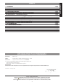 3
3
-
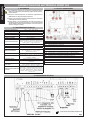 4
4
-
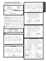 5
5
-
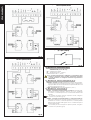 6
6
-
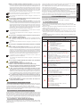 7
7
-
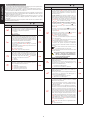 8
8
-
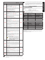 9
9
-
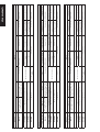 10
10
-
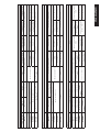 11
11
-
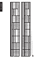 12
12
-
 13
13
-
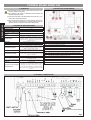 14
14
-
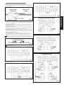 15
15
-
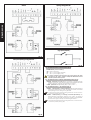 16
16
-
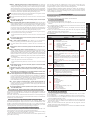 17
17
-
 18
18
-
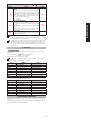 19
19
-
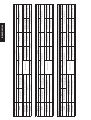 20
20
-
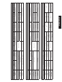 21
21
-
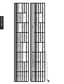 22
22
-
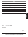 23
23
-
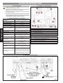 24
24
-
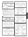 25
25
-
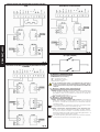 26
26
-
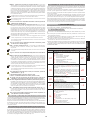 27
27
-
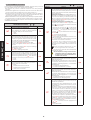 28
28
-
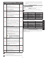 29
29
-
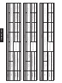 30
30
-
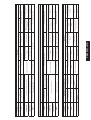 31
31
-
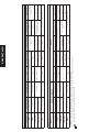 32
32
-
 33
33
-
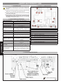 34
34
-
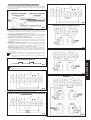 35
35
-
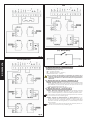 36
36
-
 37
37
-
 38
38
-
 39
39
-
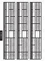 40
40
-
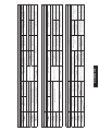 41
41
-
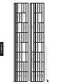 42
42
-
 43
43
-
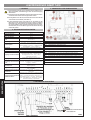 44
44
-
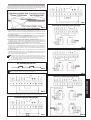 45
45
-
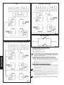 46
46
-
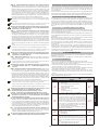 47
47
-
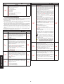 48
48
-
 49
49
-
 50
50
-
 51
51
-
 52
52
-
 53
53
-
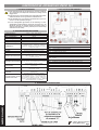 54
54
-
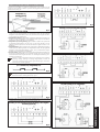 55
55
-
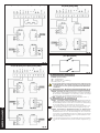 56
56
-
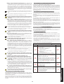 57
57
-
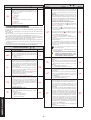 58
58
-
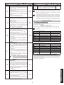 59
59
-
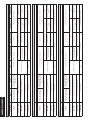 60
60
-
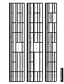 61
61
-
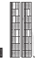 62
62
-
 63
63
-
 64
64


in altre lingue
- français: Genius SPRINT382 Mode d'emploi
- español: Genius SPRINT382 Instrucciones de operación
- Deutsch: Genius SPRINT382 Bedienungsanleitung
- Nederlands: Genius SPRINT382 Handleiding
Documenti correlati
-
Genius BRAIN18 Istruzioni per l'uso
-
-
Genius BRAIN17 Istruzioni per l'uso
-
Genius BRAIN03 BRAIN04 Istruzioni per l'uso
-
-
-
-
Genius SPRINT382 383 Istruzioni per l'uso
-
-