SBC Bidirectional 3-phase-energy-meter ALE3 Mounting Instructions & Users Guide
- Tipo
- Mounting Instructions & Users Guide

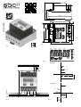
Pic. 1
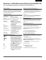
Pic. 3
Pic. 2
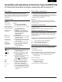
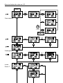
Pic. 4
kWh
L1
L2
L3
N
(PEN)
3 × 230/400 VAC
L1 L1
L2 L2
L3 L3
5 - 30V
L1
L2
L3
P+
L1 L2 L3
L2
L3
P-
L2
L1
L3
L1
Pic. 5
P positive
P negative
431951270E
27
62
4,5
6
70
65 x 11,7 = (58,5)
7
68
4,5
9
30,5
9
11
57,7
22,7
35
69,5
31
62
70
9
57.7
30.5
22.7
4.5
11
35
5 × 11.7 = [58.5]
6
4.5
27
31
45
82
69.5
768
6
9
T total T part.
T
part.
T
total

Montage- und Bedienungsanleitung Typ ALE3B5F10K
65 A-Zweiweg-Wirkenergiezähler 3-phasig mit S-Schnittstelle, Pic. 1
Beschreibung
Energiezähler mit integrierter S-Schnittstelle für die Über-
tragung von Messwerten in der Gebäudeautomatisierung.
Über das LC - Display sind zusätzliche Werte wie Momen-
tanleistungen Total oder pro Phase, sowie Spannungen
und Ströme pro Phase abzulesen.
Technische Daten
Anschlussbild
■
Pic. 2
Abmessungen
■
Pic. 3
Genauigkeitsklasse
■
B gemäss EN50470-3,
1 gemäss IEC62053-21
Referenz-,
■
Iref = 10 A, Imax = 65 A, Ist = 40 mA
Maximal-, Anlaufstrom
Betriebsspannung
■
3 × 230/400 VAC, 50 Hz
Toleranz −20%/+15%
Zählbereich
■
00 000,00…999 999,9 kWh
S-Ausgang
■
Optokoppler max. 30
V /20
mA
und mind. 5 V, Impedanz 100
,
Impulsbreite 30
ms
1000
Imp./kWh
LED
■
1000 Imp/kWh
Anschlüsse
■
Leiterquerschnitt 1,5−16 mm
2
,
Hauptstromkreis Schraubendreher Pozi Nr. 1, Schlitz
Nr. 2, Anzugsmoment 1,5−2 Nm
Anschlüsse
■
Leiterquerschnitt max. 2,5 mm
2
,
Steuerstromkreis Schraubendreher Pozi Nr. 0, Schlitz
Nr. 2, Anzugsmoment 0,8 Nm
Betriebstemperatur
■
−25… +55 °C
(nicht kondensierend
gemäss Norm EN50470)
Umgebungs-
■
Mechanische M2
bedingungen Elektromagnetische E2
Hinweise vor dem Anschliessen
1. Nicht die Phase L1, L2 oder L3 an N anschliessen.
2. Um Feuchtigkeit im Zähler durch Kondenswasser zu
vermeiden, den Zähler vor dem Anschliessen ca. eine
halbe Stunde bei Raumtemperatur akklimatisieren.
3. N muss immer angeschlossen sein.
Achtung!
Diese Geräte dürfen nur durch eine Elektrofachkraft
installiert werden, andernfalls besteht Brandgefahr oder
Gefahr eines elektrischen Schlages!
EG-Konformitätserklärung
Wir, Saia-Burgess Controls AG, CH 3280 Murten (Schweiz),
erklären in alleiniger Verantwortung, dass die Energie-
zählerprodukte:
■
ALE3B5F10KC3A00
auf die sich die Erklärung bezieht, mit der Richtlinie
2004/22/EG und den folgenden Normen oder normativen
Dokumenten übereinstimmen:
■
EN50470 Teile 1 und 3 (Elektronische Zähler),
Oktober 2006.
Murten, 30.04.2013
Konformitätsbewertungsstelle:
METAS-Cert, Nr. 1259
CH-3003 Bern-Wabern
Gezeichnet: Urs Tanner, Site Quality Leader
Deutsch
Montagehinweis
Die 3-Phasen-Energiezähler lassen sich auf eine 35 mm
Schiene (EN60715TH35) aufschnappen. Sie dürfen nur
in dazu geeigneten Installationsschränken verwendet
werden.
4 319 5127 0E 03.2017 Änderungen technischer Daten vorbehalten
Anzeigeelemente (Pic. 4)
T total (kWh)
■
Zeigt den totalen Energieverbrauch
T part. (kWh)
■
Zeigt den partiellen Energiever-
brauch, dieser Wert ist rückstellbar
T total (kWh)
■
Zeigt die totale Energierückspeisung
T part. (kWh)
■
Zeigt die partielle Energierück-
speisung, dieser Wert ist rückstellbar
P(kW)
■
Zeigt die momentane Leistung pro
Phase oder aller Phasen zusammen
Strom = Bezug (positiv)
Strom = Rückspeisung (negativ)
U(V)
■
Zeigt die Spannung pro Phase
I(A)
■
Zeigt den Strom pro Phase
kWh
■
Zeigt die Einheit kWh bei
Verbrauchsanzeige
L1 / L2 / L3
■
Bei P-, U-, I- oder Error-Anzeige wird
die entsprechende Phase angezeigt
Error
■
Bei fehlender Phase. Die entspre-
chende Phase wird zusätzlich
angezeigt.
Funktionsweise (Pic. 5)
Die Energie wird abhängig vom Vorzeichen addiert.
Positive Leistung im Zähler bedeutet Energiebezug, eine
negative Leistung bedeutet Energielieferung.
Die S-Pulse werden abhängig der Energieussrichtung
ausgegeben. Diese Funktion kann über das Menu
eingestellt werden.
in = Pulse nur bei Energie Verbrauch
out = Pulse nur bei Energie Rückspeisung
bi = beide Energieussrichtungen

Assembly and operating instructions Type ALE3B5F10K
65 A bidirectional three-phase active power energy meter with S-interface, Pic.
1
Description
Energy meter with S-interface for the integrated
transmission of measured values in building automation.
The LC - display add values such as total or instantaneous
power per phase, and read voltages and currents for
each phase.
Technical data
Connection
■
Pic. 2
diagram
Dimensions
■
Pic. 3
Accuracy class
■
B according to EN50470-3,
1 according to IEC62053-21
Reference, Maxi-
■
Iref = 10 A, Imax = 65 A, Ist = 40 mA
mum, initial current
operating voltage
■
3 × 230/400 VAC, 50 Hz
Tolerance −20%/+15%
Counting range
■
00 000,00…999 999,9 kWh
S-Ouptut
■
Optocoupler max. 30
V/20
mA
and min. 5V, impedance 100
Ω,
pulse duration 30
ms
1000
Imp./kWh
LED
■
1000 Imp/kWh
Connections
■
Conductor cross-section 1,5−16 mm
2
,
Main circuit screwdriver pozi no. 1, slot no. 2,
torque 1,5−2 Nm
Connections
■
Conductor cross-section max. 2,5 mm
2
,
Control circuit screwdriver pozi no. 0, slot no. 2,
torque 0,8 Nm
Operating
■
−25… +55°C (noncondensing
temperature according standard EN50470)
Environment
■
Mechanical M2
Electromagnetic E2
Notes before connecting
1. Do not connect L1, L2 or L3 to N
2. In order to avoid moisture in the meter due to conden-
sate build-up, acclimatise the meter at room temperature
for about half an hour before connecting.
3. N must always be connected.
Attention!
These devices must only be installed by a professional
electrician, otherwise there is the risk of re or the risk of
an electric shock.
Declaration of Conformity CE
We, Saia-Burgess Controls AG, CH 3280 Murten (Switzer-
land), herewith declare, on our own responsibility that
the products:
■
ALE3B5F10KC3A00
which this certicate refer to, are in accordance with the
directive 2004/22/EG (MID) and the following standards:
■
EN50470 parts 1 and 3 (electronic meter), of
October 2006.
Murten, 30.04.2013
Conformity Assessment Body:
METAS-Cert, Nr. 1259
CH-3003 Bern-Wabern
Signed: Urs Tanner, Site Quality Leader
English
Installation instructions
The three-phase energy meter can be attached to a 35 mm
rail (EN60715TH35).
The meter can be used only in installation cabinets.
4 319 5127 0E 03.2017 Subject to change without notice
Indicating elements
(Pic. 4)
T total (kWh)
■
Shows total consumption Tariff
T part. (kWh)
■
Shows partial consumption, this
value is resettable
T total (kWh)
■
Shows total feeding back Tariff
T part. (kWh)
■
Shows partial feeding back, this
value is resettable
P(kW)
■
Shows the instantaneous power
per phase or all phases.
Current = consumption (pos.)
Current = recovery (neg.)
U(V)
■
Shows the voltage per phase
I(A)
■
Shows the current per phase
kWh
■
Shows the unit kWh when the
consumption is displayed
L1 / L2 / L3
■
For P-, U-, I- or Error display, the
corresponding phase is displayed
Error
■
In case of missing phase, the cor-
responding phase is additionally
displayed.
Method of operation (Pic. 5)
Energy is added as indicated by the arithmetic operator.
Positive output in the meter indicates that energy is being
supplied, while negative output indicates that energy is
being delivered.
The S pulses are issued depending of the direction of the
energy ow. This function can be set from the menu.
in = pulses only for energy consumption
out = pulses only for energy recovery
bi = both energy ow directions

Start
> 3 s
> 3 s
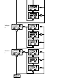
Menu to display the value on LCD
Instan.
Power P
total
part.
total
part.
> 3 s
Start
> 20 s
Consumption
Feeding back

Saia-Burgess Controls AG
Bahnhofstrasse 18 I CH-3280 Murten I Schweiz
T +41 26 580 30 00 I F +41 26 580 34 99
www.sbc-support.com

Italiano
Istruzioni d’uso e montaggio Modello ALE3B5F10K
Contatore d’energia attiva trifase 65 A bidirezionale con interfaccia S, Pic. 1
Descrizione
Contatori di energia con interfaccia S per la trasmissione
integrata dei valori misurati nel «building automation».
Display LCD per visualizzare i valori aggiuntivi come
potenza totale o istantanea per fase, e leggere tensioni e
correnti per ogni fase.
Dati tecnici
Schema di
■
Pic. 2
collegamento
Dimensioni
■
Pic. 3
d’ingombro
Classe di
■
B secondo EN50470-3,
precisione 1 secondo IEC62053-21
Corrente di riferi-
■
Iref = 10 A, Imax = 65 A, Ist = 40 mA
mento, massima, di spunto
Tensione
■
3 × 230/400 VAC, 50 Hz
d’esercizio Tolleranza −20%/+15%
Capacità di
■
00 000,00…999 999,9 kWh
conteggio
Uscita S
■
Optoisolatore max. 30
V20
mA
e min. 5
V, impedenza 100 Ω,
ampiezza impulsi 30 ms
1000 Imp./kWh
LED
■
1000 Imp/kWh
Morsetti
■
Sezione conduttori 1,5−16 mm
2
,
circuito principale
cacciavite pozi nr. 1, a taglio nr. 2,
coppia di serraggio 1,5−2 Nm
Morsetti
■
Sezione conduttori max. 2,5 mm
2
,
circuito di comando
cacciavite pozi nr. 0, a taglio nr. 2,
coppia di serraggio 0,8 Nm
Temperatura
■
−25 … +55°C (assenza di
d’esercizio condensa secondo la norma
EN50 470)
Ambienti
■
meccanici M2
elettromagnetici E2
Dichiarazione di conformità CE
Noi, Saia-Burgess Controls AG, CH 3280 Murten (Svizzera),
dichiarammo in nostra propria responsabilita che i
prodotti:
■
ALE3B5F10KC3A00
di quali si riferisce questa dichiarazione rispondono alla
direttiva 2004/22/CE (MID) e alle normative seguente:
■
normativa EN50470 Parte 1 e 3
(Contatori elettronici). Octobre 2006
Murten, 30.04.2013
Organismi di valutazione della conformità:
METAS-Cert, Nr. 1259
CH-3003 Bern-Wabern
Firmato: Urs Tanner, Site Quality Leader
Note per il collegamento
1. Non collegare la fase L1, L2 o L3 a N.
2. Per evitare la presenza di umidità nel contatore in
seguito alla formazione di acqua di condensa, prima del
collegamento lasciare il contatore per circa mezz’ora a
temperatura ambiente
3. N deve sempre essere collegato.
Attenzione!
Questi apparecchi devono essere installati esclusivamente
da elettricisti specializzati, onde evitare rischi di incendio o
pericoli di scosse elettriche!
Istruzioni di montaggio
I contatori di energia trifase si installano su guida da
35 mm (EN60715TH35). Devono essere installati solo in
quadri o centralini
4 319 5127 0E 03.2017 Soggetto a modiche senza preavviso
Elementi a display
(Pic. 4)
T total (kWh)
■
indica il consumo totale
T part. (kWh)
■
indica il consumo parziale; questo
valore è azzerabile
T total (kWh)
■
indica il recupero totale
T part. (kWh)
■
indica il recupero parziale; questo
valore è azzerabile
P(kW)
■
indica la potenza istantanea per
ciascuna fase o per tutte le fasi
corrente = consumo (pos.)
corrente = recupero (neg.)
U(V)
■
indica la tensione per ciascuna fase
I(A)
■
indica la corrente per ciascuna fase
kWh
■
indica il consumo rilevato in kWh
L1 / L2 / L3
■
è la fase interessata per P,U,I o Errore
Error
■
In caso di mancanza di una fase.
Viene visualizzata la fase interessata
Tipo di funzionamento (Pic. 5)
L‘energia verrà sommata in base al segno. La potenza po-
sitiva sul contatore indica il prelievo di energia, la potenza
negativa indica l’immissione di energia.
Gli impulsi S vengono emessi a seconda della direzione
del usso di energia.
Questa funzione può essere impostata dal menu.
in = impulsi solo nel consumo di energia
out = impulso solo per il recupero di energia
bi = entrambe le direzioni di usso di
energia

Francais
4 319 5127 0E 03.2017 Sous réserve de modications sans préavis
Instructions de montage et d’utilisation ALE3B5F10K
Compteur d’énergie active triphasé 65 A bidirectionnelle avec S-interface, Pic.1
Description
Compteurs d‘énergie avec interface S intégrée pour la
transmission des valeurs mesurées dans l‘automatisation
du bâtiment. Le LC - display ache des valeurs addition-
nelles telles que l‘énergie totale ou instantanée par phase,
ainsi que les tensions et courants pour chaque phase.
Caractéristiques techniques
Schéma de
■
Pic. 2
raccordement
Dimensions
■
Pic. 3
Classe de
■
B selon EN50470-3,
précision 1 selon IEC62053-21
Courant de
■
Iref = 10 A, Imax = 65 A, Ist = 40 mA
référence, maximal, de démarrage
Tension de service
■
3 × 230/400 VAC, 50 Hz
Tolérance −20%/+15%
Plage de comptage
■
00 000,00 à 999 999,9 kWh
Sortie S
■
Optocoupleur max. 30
V/20
mA
et min. 5V, impédance 100
Ω,
largeur d’impulsion 30
ms
1000
Imp./kWh
LED
■
1000 Imp/kWh
Branchements
■ Section de conducteur
1,5−16 mm
2
,
Circuit d’alimentation tournevis pozi n° 1, plat n° 2,
couple de serrage 1,5−2 Nm
Branchements
■
S
ection de conducteur maximal
Circuit de commande
2,5 mm
2
, t
ournevis pozi n° 0, plat
n° 2, couple de serrage 0,8 Nm
Température de
■
−25 à +55°C (sans condensation
service selon la norme EN50470)
Environnement
■
mécanique M2
electromagnétiques E2
Déclaration de conformité CE
Nous, Saia-Burgess Controls AG, CH 3280 Murten (Suisse),
déclarons sous notre propre responsabilité que les
produits:
■
ALE3B5F10KC3A00
pour lesquels cette déclaration se référe sont conformes à
la directive 2004/22/CE (MID) et aux normes suivantes:
■
EN50470 Parties 1 et 3 (Compteurs électroniques).
Octobre 2006
Murten, 30.04.2013
Organismes d’évaluation de la conformité:
METAS-Cert, Nr. 1259
CH-3003 Bern-Wabern
Signé : Urs Tanner, Site Quality Leader
Remarque préalable au raccordement
1. Ne pas raccorder la phase L1, L2 ou L3 à N.
2. An d’éviter la formation de condensation dans le
compteur, laisser celui-ci s’acclimater pendant env. une
demi heure à la température ambiante du local.
3. N doit toujours être connecté.
Attention!
Ces appareils doivent être uniquement installés par un
spécialiste en électricité pour éviter tout risque d’incendie
ou d’électrocution !
Instructions de montage
Les compteurs d’énergie Triphasé peuvent être encliquetés
sur un rail de 35 mm (EN60715TH35). Ils ne peuvent être
utilisés que dans des armoires électriques.
Eléments d’achage
(Pic. 4)
T total (kWh)
■
Indique la consommation totale
T part. (kWh)
■
Indique la consommation partielle,
cette valeur est réinitialisable
T total (kWh)
■
Indique la récupération totale
T part. (kWh)
■
Indique la récupération partielle, cette
valeur est réinitialisable
P(kW)
■
Indique la puissance instantanée
par phase ou de toutes les phases
Courant = consommation (pos.)
Courant = récupération (neg.)
U(V)
■
Indique la tension par phase
I(A)
■
Indique le courant par phase
kWh
■
I
ndique l’unité kWh pour l’affichage
de consommation
L1 / L2 / L3
■
En cas d’affichage P, U, I ou Error, la
phase correspondante s’affiche
Error
■
En cas d’absence de phase. La
phase correspondante s’affiche
également.
Fonctionnement (Pic. 5)
L‘énergie est ajoutée en fonction du signe. Une puissance
positive signie une alimentation en énergie, une puis-
sance négative signie une fourniture d‘énergie.
Les impulsions S sont données selon de la direction du
ux énergétique. Cette fonction doit être paramétrée à
partir du menu.
in = impulsions uniquement lors de consommation
out = impulsions uniquement lors de production d’énergie
bi = impulsions quelle que soit la direction

Voltage
U
Current
I
Start
-
 1
1
-
 2
2
-
 3
3
-
 4
4
-
 5
5
-
 6
6
-
 7
7
-
 8
8


SBC Bidirectional 3-phase-energy-meter ALE3 Mounting Instructions & Users Guide
- Tipo
- Mounting Instructions & Users Guide
in altre lingue
Documenti correlati
-
SBC Single-phase energy meter ALD1 Mounting Instructions & Users Guide
-
SBC Saia PCD ALD1B5F10K Mounting Instructions & Users Guide
-
-
-
-
-