Pyronix DELTABELL-WE Guida d'installazione
- Tipo
- Guida d'installazione

Step 4
Warranty and compliance
Technical Specification
Printed Circuit Board Battery
DELTABELL-WE
Self Powered External Sounder
Installation guide
Installation Steps: Step 1
Step 2
Step 3
EN50131-4:2009
EN50131-5-3:2005+A1:2008
Security Grade 2
Environmental Class IV
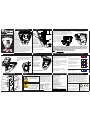
Slide the
PCB
module
upwards.
The sprung
back-tamper
arm can be
retracted to
allow removal.
This must be
done in order to
install the revolving
guides - see step 3.
Place the base on a
flat surface and
ensure it is vertical
using the spirit level
that is already installed. Drill and plug in each of the
fixing locations. The revolving guides will correct any
misalignment. If the Deltabell WE must be mounted
on an uneven surface, it is recommended that a
tamper levelling screw is used to ensure correct
back-tamper operation. See step 2.
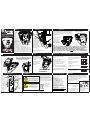
Step 5
Fit the lid by sliding its
hinges into place. The lid
can be supported in the
fully open position. To
close the lid, apply a
little force to push the lid
past the holds.
Close the cover, ensure
the tamper is operating
correctly, insert the
25mm long screw
supplied and rotate the
screw cover to a close.
*Lid sold separately
Mounting the
Deltabell WE on an
uneven surface
may cause false
triggering, through
incorrect operation of
the back-tamper.
A POZI number 2 screw
driver is recommended for
adjusting back tamper screw.
NOTE: This is for wall mounting only.
Low voltage Threshold:
Batt1: 2.2V +/-5% at 25 C,
Batt2: 2.5V +/-5% at 25 C
Batteries: 2x 3V 5AHr
Lithium battery packs (BATT-ES1)
Acoustic output: Tone.
Strobe duration: 10ms
Strobe Frequency: 1Hz
Sound pressure level: 101dBA
Max sound duration: 15 mins
Dimensions: 290 x 285 x 50 mm
Selectable comfort LEDs:
4 second flash rate
Operation from external PSU (optional):
11V to 14V
IMPORTANT NOTE: The batteries should
still be connected if using an external PSU.
Case Tamper. Reverse polarity protected
The batteries supplied have been
chosen to provide long service life
whilst, for safety reasons, having
limited output current. Replace
only with approved batteries.
To prevent possible damage to
components, any static charge on
your body needs to be eliminated
before touching the inside of the
unit. This can be accomplished by
touching some grounded/earthed
metallic conductor such as a
radiator/pipework immediately
before replacing batteries.
Insert the guides as shown. Make sure that the guides ‘B’
are aligned with the tabs to the right (this is so the PCB
module slides in). Turn each guide until they line up with the
drilled holes, while referencing the spirit level for the correct
alignment, and fix the base firmly to the wall.
Please note, if the Deltabell
WE is installed on an uneven
surface, it is recommended
that you do not tighten up
the wall screws until after
the module is installed
(step 4)
The batteries and battery holder
should be inserted as shown:
Learning the DELTABELL-WE onto the Control Panel
When you are ready to learn the device to the
control panel receiving equipment, and when
the equipment is in the learn mode (see the
Control Panel Programming Manual) follow the
procedure below.
1. Make sure the battery is installed correctly
2. Press and hold the Learn button until the
3 LEDs start cycling through the different
colours, then release.
3. The device is correctly learnt when the
green LED flashes.
WARRANTY: This product is sold subject to our standard
warranty against defects in workmanship for a period of two
years (batteries excluded). Please note: In positions where
the Deltabell WE casing is subjected to high levels of U.V.
sunlight, there may be risk of case colour fading, this is not
covered by the warranty. In the interest of continuing
improvement of quality, customer care and design, Pyronix
Ltd reserve the right to amend specifications without giving
prior notice.
Pyronix Ltd, Braithwell Way, Hellaby,
Rotherham, South Yorkshire, S66 8QY
Customer support: +44(0)845 6434 999
(local rate) or +44(0)1709 535225
Hours: Mon to Fri, 8.00am till 6:30pm
Email: customer[email protected]
Website: www.pyronix.com
The three coloured LEDs give a
visual indication of the signal
strength.
Green indicates good signal strength
and is a good location to install.
Red indicates poor signal
strength and the device should not
be installed in that position.
If no LED illuminates then the device
is completely out of range.
The blue LED will illuminate when the
device is activated.
RED BLUE GREEN
RED BLUE GREEN
RED BLUE GREEN
RED BLUE GREEN
RED BLUE GREEN
Tamper
levelling
screw
BATT1
BATT2
SOUNDER
TAMPER
COMFORT
LEDS
LED OFF
LED ON
LEARN
LED3LED2 LED1
Comfort LED
Enable/Disable
link
Learn button
Optional
auxillary 12
volt PSU input
PLEASE
NOTE:
The auxillary
12V PSU input
is not polarity
conscious
Battery
Connectors
Sounder
Tamper
Red LED
Blue LED
Green LED
Strobe
Comfort LEDs
RINS1433-3
Tamper switch
For electrical products sold within
the European Community. At the
end of the electrical products life, it
should not be disposed of with
household waste. Please recycle
where facilities exist. Check with
your Local Authority or retailer for
recycling advice in your country.
When disposing of
the product, the
battery must be
removed and
disposed of
separately in
accordance with the
local regulations
Please see the Enforcer 32-WE user,
programming and quick set up manuals for
further information
Place the PCB module, ensuring that the arrow is aligned with the marker (on the left of
the module). Expose the terminals by releasing the latch on the top of the PCB module.
NOTE: The bottom battery holder should be
installed as shown -in order to allow to
installation or removal of the Deltabell
Module.
NOTE: Older Deltabell products were supplied with a single cylindrical
battery type (1x BATT-CR34615D) instead of the two square batteries
(2x BATT-ES1) in the current product. The different battery types are
NOT INTERCHANGEABLE between products.
Replace like with like under all circumstances.

2.5V +/-5% at
Soglia di Bassa tensione 25ºC
Batteria D Cell 3.0 volt
11000MAh
Lithium battery
Uscita Acustica Tone
Durata Lampeggiante 10mS
Frequenza lampeggiante 1Hz
Livello pressione suono 93dBA
Durata massima suono 15 min
Dimensioni 290 x 285 x 50 mm
Portata Radio 1.6km
Abilitazione/
Disabilitazione
del LED di Stato
Tasto
Memorizzazione
Ingresso 12V
ausiliario DC/AC
Batteria
Sirena
LED Rosso
LED Blu
LED Verde
Lampeggiante
LED di Stato
NOTA:
l’ingresso 12v
e’ privo di
polarita’
Passo 4
Garanzia
Specifiche Tecniche
Circuito Stampato La Batteria
DELTABELL-WE
Sirena esterna autoalimentata
Guida di Installazione
Passo 1
Passo 2
Passo 3
EN50131-4:2009
EN50131-5-3:2005+A1:2008
Grado Disicurezza 2
Classe Avibientale II
Spostare
verso l’alto
il circuito
stampato.
Tirare
indietro la
molletta
posteriore per
la rimozione.
Cio’ permette
l’installazione
delle guide
girevoli. Posizionare
la base su una
superficie piatta ed
assicurarsi che sia
verticale tramite la
livella della sirena. Eseguire dei fori in
corrispondenza dei buchi di fissaggio. Le guide
girevoli correggeranno ogni disallineamento. Se la
sirena deve essere installata su una superficie non
piana, si raccomanda l’utilizzo di una vite di
livellamento per il tamper posteriore (vedi passo 2)
Passo 5
Fissare il coperchio
facendolo scorrere sulle
guide apposite e fare
pressione fino a quando
non risulta assicurato
alla guida.
Assicurarsi che il tamper
operi correttamente,
inserire la vite da 25mm
e chiudere.
Installare la sirena
su superfici non
piane puo’ causare
falsi allarmi a causa
del funzionamento
non corretto del
tamper posteriore.
Regolare la vite del
tamper posteriore tramite
un cacciavite.
NOTA: solo per installazioni a muro.
Soglia di Bassa tensione:
Batt1: 2.2V +/-5% at 25 C,
Batt2: 2.5V +/-5% at 25 C
Batteria: 2x 3V 5AHr
Lithium battery packs (BATT-ES1)
Uscita acustica: Tone.
Duranta lampeggiante: 10ms
Frequenza lampeggiante: 1Hz
Livello pressione suono: 101dBA
Durata massima suono: 15 mins
Dimensioni: 290 x 285 x 50 mm
LEDs di Stato selezionabile:
Lampeggio 4 sec
Range consentito dall’alimentatore
esterno: 11V to 14V
NOTE IMPORTANTI: Collegare le batterie
se utilizzate un alimentatore esterno.
Tamper antiapertura.
Protezione contro l’inversione della polarità
Le batterie fornite sono state scelte
per garantire lunga durata
avendo una corrente di uscita
limitata.
Al momento dell’acquisto, la
batteria e’ gia inserita nel contatto
ed e’ resa inattiva dalla presenza
di un pezzetto di plastica che va
rimosso per farla funzionare.
Per prevenire possibili Danni ai
componenti, ogni carica statica
deve essere eliminata prima di
toccare la parte interna
dell’unita’. Cio puo’ essere
ottenuto toccando un metallo/con-
duttore messo a terra prima di
sostituire la betteria.
Inserire le guide come mostrato. Assicurarsi che le guide
“B” siano allineate con le alette sulla destra. Ruotare tutte
le guide fino al loro allineamento con i fori eseguiti con il
trapano e controllare la livella per un corretto allineamen-
to. Fissare la base al
muro.
NOTA: se la sirena viene
installata su una
superficie non piana, si
raccomanda di non
stringere eccessivamente
le viti fino a quando il
modulo e’ installato.
La batteria e il supporto devono essere
inseriti come mostrato:
Memorizzare il DELTABELL-WE sulla sistema centrale
Quando la centrale si trova in modalita’
tecnica, e’ possibile memorizzare la
Sirena radio. Seguire la procedura
seguente:
I. Assicurarsi che la batteria sia
correttamente installata
II. Tenere premuto il tasto di memoriz-
zazione fino a quando i 3 led non si
attivano ciclicamente, dopodiche’
rilasciarlo.
III. Se il dispositivo viene memorizzato
correttamente, il led verde lampeggiera’.
Questo prodotto viene venduto secondo le nostre
condizioni di garanzia ed e’ garantito per 2 anni contro
difetti di fabbricazione (escluse le batterie). Nell’ottica di
continuare a migliorare la qualita’, i progetti e la cura del
cliente, Pyronix Ltd si riserva il diritto di
emendamento sulle specifiche
senza dare preavviso.
I 3 led colorati danno un’indicazione
visiva della potenza di segnale:
Verde indica una buona Potenza di
segnale e un buona posizione per
l’installazione
Rosso indica uno scarso segnale
radio ed un cattivo punto di
installazione
Se nessun led si illumine la sirena e’
fuori copertura
Il led blu si illuminera’ quando il
dispositivo e’ attivato
RED BLUE GREEN
RED BLUE GREEN
RED BLUE GREEN
RED BLUE GREEN
RED BLUE GREEN
Vite
regolazione
tamper
BATT1
BATT2
SOUNDER
TAMPER
COMFORT
LEDS
LED OFF
LED ON
LEARN
LED3LED2 LED1
Tamper
RINS1433-3
Meccanismo di
tamper
La vendita del prodotto nei paesi
della comunita’ europea, ne
prevede il corretto smaltimento
in appositi contenitori. Riciclare il
prodotto dove esistono tali
raccoglitori. Chiedere al rivenditore
dove e come eseguire il riciclaggio.
La batteria deve
essere rimossa
e riciclata
separatamente.
Consultare il manuale di programmazi-
one e la guida veloce per informazioni
aggiuntive.
Posizionare la scheda integrata allineando la freccia con l’etichetta (sulla sinistra del
modulo). Aprire il coperchio sopra la scheda integrata e scoperchiare i morsetti di
connessione .
NOTA : Il supporto della batteria inferiore
deve essere installato come mostrato
Nell'ordine per consentire di installazione o
la rimozione del modulo Deltabell .
NOTA:
Le versioni precedenti di Deltabell sono state fornite con un’unica
tipologia di batteria cilindrica (1x BATT-CR34615D) al posto delle due
batterie quadrate (2x BATT-ES1) utilizzate nel prodotto corrente.
Le due diverse tipologie di batterie NON SONO INTERCAMBIABILI tra i
prodotti. In qualsiasi caso, sostituire la batteria con lo stesso modello.
Guide
Girevoli
Livella
*COPERCHIO VENDUTO
SEPARATAMENTE
Pyronix Ltd, Braithwell Way, Hellaby,
Rotherham, South Yorkshire, S66 8QY
Supporto Clienti: +44(0)845 6434 999
o +44(0)1709 535225
Ore: Da Lun a Ven, 8.00am till 6:30pm
Email: customer[email protected]
Website: www.pyronix.com
-
 1
1
-
 2
2


Pyronix DELTABELL-WE Guida d'installazione
- Tipo
- Guida d'installazione
in altre lingue
Documenti correlati
-
Pyronix Enforcer DELTABELL-WE Guida d'installazione
-
-
-
-
-
-
-
-
-