
1
CARDIN ELETTRONICA spa
Via Raffaello, 36
31020 San Vendemiano (TV) Italy
Tel: +39/0438.404011-401818
Fax: +39/0438.401831
email (Italy): Sales.office.it@cardin.it
email (Europe): Sales.office@cardin.it
Http: www.cardin.it
This product has been tried and tested in
the manufacturer's laboratory, during the
installation of the product follow the supplied
indications carefully.
PRG304
ZVL484.00
PROGRAMMATORE ELETTRONICO MONOFASE PER IL COMANDO DI SERRANDE MOTORIZZATE
SINGLE PHASE ELECTRONIC PROGRAMMER CONTROLLING MOTORISED SHUTTERS
PROGRAMMATEUR ÉLECTRONIQUE MONOPHASÉ POUR LA COMMANDE DE RIDEAUX À ENROULEMENT MOTORISÉS
EINPHASIGE ELEKTRONISCHE STEUERUNG ZUR BEFEHLUNG VON MOTORISIERTEN ROLLLÄDEN
PROGRAMADOR ELECTRÓNICO MONOFÁSICO PARA EL MANDO DE CIERRES MOTORIZADOS
PRELIMINARY INSTRUCTIONS
AVVERTENZE IMPORTANTI Pagina 3
CARATTERISTICHE TECNICHE Pagina 3
SCHEDA BASE Pagina 4
COLLEGAMENTO ELETTRICO Pagina 5
PROGRAMMAZIONE TEMPI Pagina 6
MODALITÀ DI FUNZIONAMENTO Pagina 6
COMANDO VIA RADIO Pagine 6-7
IMPORTANT REMARKS Page 8
TECHNICAL SPECIFICATIONS Page 8
MOTHER BOARD Page 9
ELECTRICAL CONNECTION Page 10
TIME PROGRAMMING PROCEDURE Page 11
FUNCTION MODE Page 11
REMOTE CONTROL Pages 11-12
CONSIGNES DE SÉCURITÉ Page 13
CARACTÉRISTIQUES TECHNIQUES Page 13
CARTE DE BASE Page 14
BRANCHEMENT ÉLECTRIQUE Page 15
PROGRAMMATION DES TEMPS Page 16
MODES DE FONCTIONNEMENT Page 16
COMMANDE VIA RADIO Pages 16-17
WICHTIGE HINWEISE Seite 18
TECHNISCHE DATEN Seite 18
ELEKTRONISCHE PLATINE Seite 19
ELEKTROANSCHLUSS Seite 20
ZEITEN-PROGRAMMIERVERFAHREN Seite 21
BETRIEBSMODUS Seite 21
FUNKSTEUERUNG Seiten 21-22
ADVERTENCIAS IMPORTANTES Página 23
ESPECIFICACIONES TECNICAS
Página 23
TARJETA BASICA Página 24
CONEXIÓN ELECTRICA
Página 25
PROGRAMACION DE LOS TIEMPOS
Página 26
MODALIDAD DE FUNCIONAMIENTO Página 26
MANDO VÍA RADIO
Páginas 27-28
ITALIANO
ENGLISH
ESPAÑOL
DEUTSCH
FRANÇAIS
PRG304
ZVL484.00 MOD: 14-03-2006

2
Line 230V~
Scheda base
PRG304
13-03-2006
DC0433
Description :
Product Code :
Date :
Drawing number :
P.J.Heath
CARDIN ELETTRONICA S.p.A - 31020 San Vendemiano (TV) Italy - via Raffaello, 36 Tel: 0438/401818 Fax: 0438/401831
Draft :
All rights reserved. Unauthorised copying or use of the information contained in this document is punishable by law
PRG304 (INSTLLAZIONE TIPO)
6 7
2 3
4
5
Chiusura
Comune
Apertura
M
1
N
F2
TB
CSP
10 11
13 14 15 16
17 18 19
12
8 9
24Vac
FTC
CSP_A
P2
1 2
ON
D1
20
TA
CMN
TC
CMN
CMN
ANEM
B1
R1
P1
J1
J2
J3
L2
L3
L
24V
12V 0
C
1
65432
NA
NC
NC
C
NA
FTC-RX
1
32
24V
12V
0
FTC-TX
1
2
CSP
1
2
LP
J3
A
1
2
CSP_A
TB
CSP
13 14 15 16
17 18
FTC
CSP_A
CMN
ANEM
B
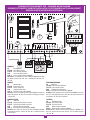
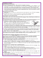
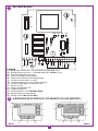
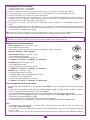
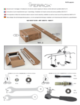
SCHEMA ELETTRICO IMPIANTO TIPO - STANDARD WIRING DIAGRAM
SCHÉMA ÉLECTRIQUE DE L'EXEMPLE D'INSTALLATION - ELEKTRISCHER SCHALTPLAN ANLAGENART
ESQUEMA ELECTRICO INSTALACIÓN ESTÁNDAR
LEGENDA
LP Lampeggiatore
FTC-RX Fotocellula ricevitore
FTC-TX Fotocellula trasmettitore
CSP Costa sensibile standard
CSP_A Costa sensibile analogica (8,2 kΩ)
Attenzione: per utilizzare una costa analogica (8,2 kΩ) ricordarsi
di estrarre il jumper "J3" dett. "A" e di utilizzare il morsetto "17"
dett. "B".
LEGEND
LP Warning lights
FTC-RX Photocell receiver
FTC-TX Photocell projector
CSP Standard safety edge
CSP_A Analogical safety edge (8,2 kΩ)
Attention: to use an analogical safety edge (8,2 kΩ) remember to
remove the jumper "J3" dett. "A" and wire to binding post number
"17" dett. "B".
NOMENCLATURE
LP Clignoteur
FTC-RX Cellule photoélectrique récepteur
FTC-TX Cellule photoélectrique émetteur
CSP Bord de protection standard
CSP_A Bord de protection analogique (8,2 kΩ)
Attention: Pour utiliser un bord de sécurité analogique (8,2 kΩ),
se rappeler de retirer le cavalier "J3" (dét. "A") et d’utiliser la borne
"17" (dét. "B").
ZEICHENERKLÄRUNG
LP Blinklicht
FTC-RX Lichtschranke Empfänger
FTC-TX Lichtschranke Sender
CSP Standard Sicherheitsleiste
CSP_A Analogische Sicherheitsleiste (8,2 kΩ)
Achtung: um die Analogische-Sicherheitsleiste (8,2 kΩ) zu verwen-
den ist es notwendig den jumper "J3" dett. "A" herauszuziehen und
die Klemme "17" dett. "B" verwenden.
LEYENDA
LP Relampagueador
FTC-RX Fotocélula receptor
FTC-TX Fotocélula emisor
CSP Banda sensible standard
CSP_A Banda sensible analógica (8.2 kΩ)
Atención! para utilizar la banda sensible analógica (8,2 kΩ) acor-
darse de desenchufar el puente "J3" det. "A" y de utilizar el borne
"17" det. "B".

3
• Il presente manuale si rivolge a persone abilitate all'installazione di "apparecchi utilizzatori di energia
elettrica" e richiede una buona conoscenza della tecnica, esercitata in forma professionale e della nor-
mativa vigente.
I materiali usati devono essere certificati e risultare idonei alle condizioni ambientali di installazione.
• Le operazioni di manutenzione devono essere eseguite da personale qualificato. Prima di eseguire qual-
siasi operazione di pulizia o di manutenzione, disinserire l'apparecchiatura dalla rete di alimentazione
elettrica.
• Le apparecchiature qui descritte dovranno essere destinate solo all'uso per il quale sono state espressamente
concepite: "Il comando e controllo di installazioni automatiche con motorizzazione a 230Vac"
L'utilizzo dei prodotti e la loro destinazione ad usi diversi da quelli previsti e/o consigliati, non è stata speri-
mentata dal costruttore, pertanto i lavori eseguiti sono sotto la completa responsabilità dell'installatore.
• La bontà della connessione di terra dell’apparecchiatura è fondamentale ai fini della sicurezza elettrica.
• Controllare periodicamente l'integrità del cavo d'alimentazione: Se esso presenta segni di usura e/o
danneggiamento deve essere sostituito dal costruttore o dal suo servizio di assistenza tecnica.
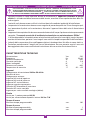
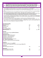
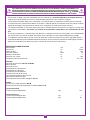
CARATTERISTICHE TECNICHE
Alimentazione Vac 230
Frequenza Hz 50-60
Potenza complessiva W 650
Corrente nominale A 2,8
Motori collegabili N° 1
Potenza max motore W 600
Temperatura di esercizio °C -20…+55
Ingressi
Collegamento alimentazione 230Vac 50-60 Hz
Morsetto di terra
Collegamento antenna
Ingresso NA tasto di apertura
Ingresso NA tasto di chiusura
Ingresso NC tasto di blocco
Ingresso segnale anemometro
Contatto NC fotocellule di inversione
Contatto NC costa sensibile
Ingresso per costa sensibile analogica (8.2 kΩ)
Uscite
Uscita per 1 motore potenza 600 W
Uscita per alimentazione dispositivi esterni 24 Vac 7 W
Tempo di lavoro
Massimo tempo programmabile sec. 180
Tempo di pausa
Minimo tempo programmabile sec. 1
Massimo tempo programmabile sec. 60
AVVERTENZE IMPORTANTI AVVERTENZE IMPORTANTI AVVERTENZE IMPORTANTI
PER RIDURRE IL RISCHIO DI FERITE GRAVI O MORTE, LEGGERE ATTENTAMENTE LE SE-
GUENTI AVVERTENZE PRIMA DI PROCEDERE ALL’INSTALLAZIONE. PRESTARE PARTICOLARE
ATTENZIONE A TUTTE LE SEGNALAZIONI DISPOSTE NEL TESTO. IL MANCATO RISPETTO
DI QUESTE POTREBBE COMPROMETTERE IL BUON FUNZIONAMENTO DEL SISTEMA.

4
CS1244AB DC0403
Line 230V~
L1
Scheda base
PRG304
10-01-2006
DC0403
Description :
Product Code :
Date :
Drawing number :
P.J.Heath
CARDIN ELETTRONICA S.p.A - 31020 San Vendemiano (TV) Italy - via Raffaello, 36 Tel: 0438/401818 Fax: 0438/401831
Draft :
All rights reserved. Unauthorised copying or use of the information contained in this document is punishable by law
PRG304
6 7
2 3
4
5
Chiusura
Comune
Apertura
M
1
N
L
MAX
C
B
A
MIN
F1
F2
S1
TB
CSP
10 11
13 14 15 16
17 18 19
12
8 9
24Vac
FTC
CSP_A
P2
1 2
ON
D1
20
TA
CMN
TC
CMN
CMN
ANEM
B1
R1
P1
J1
J2
J3
L2
L3
8
1
2
3
6 5 4
7
8
1
2
3
6 5 4
7
2
MDK RT
MDK RTL
1
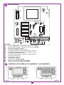
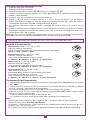
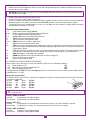
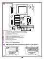
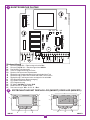
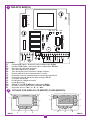
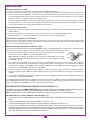
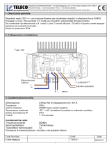
SCHEDA BASE
Legenda
F1 Fusibile 0.5 A rapido - protezione sovraccarichi 24 Vac
F2 Fusibile 3.15 A rapido - protezione sovraccarichi 230 Vac
D1 Dip-switch selezione funzioni
P1 Pulsante di programmazione tempi
P2 Pulsante di memorizzazione/cancellazione codici TX
J1 Ponticello abilitazione alla memorizzazione via radio
J2 Ponticello funzione fotocellule
J3 Ponticello funzione costa sensibile analogica 8.2 kΩ
L1 Led scheda alimentata
L2 Led gestione codici TX
L3 Led programmazione
R1 Modulo RF a 433 MHz (S449)
B1 Buzzer segnalazione modalità "via radio"
S1 Regolatore di coppia "Min-A-B-C-Max"
TASTIERA CON DISPLAY LCD (MDKRT) O LED (MDKRTL)

5
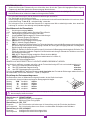
COLLEGAMENTO ELETTRICO
• Accertarsi, prima di eseguire il collegamento elettrico, che la tensione e la frequenza riportate sulla
targhetta caratteristiche corrispondano a quelle dell'impianto di alimentazione.
Attenzione! Tra la centralina di comando e la rete deve essere interposto un interruttore onnipolare, con
distanza di apertura tra i contatti di almeno 3 mm.
• Collegare i fili di comando e quelli provenienti dalle sicurezze.
• Collegare il cavo di alimentazione al dispositivo.
• Non utilizzare cavo con conduttori in alluminio; non stagnare l’estremità dei cavi da inserire in morsettiera;
utilizzare cavo con marcatura T min 85°C resistente agli agenti atmosferici.
• I conduttori dovranno essere adeguatamente fissati in prossimità della morsettiera in modo che tale
fissaggio serri sia l’isolamento che il conduttore (è sufficiente una fascetta).
Collegamenti morsettiera
1-2 Alimentazione generale 230 Vac
3-4-5 Uscita comando motore Chiusura/Apertura/Comune
6-7 Ingresso terra per alimentazione e per motore
8-9 Uscita 24 Vac 7 W alimentazione dispositivi esterni
10 TA (NA) ingresso tasto di apertura
11 TC (NA) ingresso tasto di chiusura
12-13 CMN Comune per tutti gli ingressi e uscite
14 TB (NC) ingresso tasto di blocco
15 CSP (NC) ingresso per costa sensibile. L'apertura del contatto inverte il moto nella fase di chiu-
sura e interrompe il moto nella fase di apertura (il moto riprende al successivo comando).
16 FTC (NC) ingresso per dispositivi di sicurezza (fotocellula di inversione moto in chiusura).
L'apertura del contatto, conseguente all'intervento dei dispositivi di sicurezza, durante la fase
di chiusura, attuerà l'inversione di moto.
17 CSP_A ingresso costa sensibile analogica 8.2 kΩ
18 ANEM ingresso anemometro (vedi funzionamento anemometro a pagina 6)
19 Massa antenna ricevitore radio
20 Centrale antenna ricevitore radio
N.B. TUTTI I CONTATTI N.C. NON UTILIZZATI VANNO PONTICELLATI
Alimentare il circuito e verificare che lo stato dei LED di segnalazione sia come segue:
- L1 LED verde di alimentazione circuito acceso
- L2 LED rosso di gestione codici TX spento
- L2 LED rosso di segnalazione tasto programmazione tempi spento
Nel caso in cui il LED verde "L1" di alimentazione non si accenda verificare lo stato dei fusibili ed il collega-
mento del cavo di alimentazione tra i morsetti 1-2 (fig.1).
Regolazione del limitatore di coppia
La coppia può essere regolata sui valori minimi, dato che l'apparecchiatura fornisce
un impulso alla massima potenza ad ogni comando di moto ricevuto.
Posizione "MIN" corrisponde a: 120 Vac
Posizione "A" corrisponde a: 145 Vac
Posizione "B" corrisponde a: 170 Vac
Posizione "C" corrisponde a: 195 Vac
Posizione "MAX" corrisponde a: 230 Vac
Per impostare i dip-switches/jumper: disalimentare il programmatore, cambiare le impostazioni, quindi dare
nuovamente alimentazione.
Jumper J1 “REMOTE MEMO”
Inserito: memorizzazione via radio abilitata
Disinserito: memorizzazione via radio disabilitata
Jumper J2 “SEL_FTC”
Inserito: le fotocellule impediscono anche l’attivazione del motore, se risultano in allarme
Disinserito: le fotocellule agiscono da protezione solo quando la serranda è in chiusura
Jumper J3 “CSP_A ENABLE”
Inserito: costa analogica disabilitata
Disinserito: costa analogica abilitata
M
I
N
A
B
C
M
A
X

6
Procedura di programmazione Tempi
- Tempo di lavoro max: 180 secondi
- Tempo di pausa max: 60 secondi
1) Premere e tenere premuto il tasto "P1" PROG finché si accende il LED "L3".
2) Portare la serranda in completa chiusura con il tasto "P2" MEMO/DEL (l’azionamento viene eseguito in
modalità "uomo presente").
3) Premere il tasto "P1" per dare inizio alla manovra di apertura.
4) Quando la serranda arriva in completa apertura, e si attiva il finecorsa di apertura che disalimenta il
motore, bloccandolo, attendere 3-4 secondi e poi premere nuovamente il tasto "P1": il LED "L3" comincia
a lampeggiare segnalando l’inizio del conteggio del tempo di pausa.
5) Alla successiva pressione di "P1" si termina il conteggio del tempo di pausa e la serranda inizia la
chiusura.
6) Quando la serranda arriva in completa chiusura, e si attiva il finecorsa di chiusura che disalimenta il motore,
bloccandolo, attendere 3-4 secondi e poi premere il tasto "P1"; a questo punto la programmazione tempi
è terminata ed il LED "L3" si spegne.
Nota: dopo aver attivato la procedura di programmazione, il passo 2 può essere eseguito anche premendo il
tasto "TC", e dal passo 3 in poi si può procedere anche attivando il tasto di apertura "TA".
Attenzione! Se al termine della programmazione tempi i LED "L2" ed "L3" lampeggiano simultaneamente,
vuol dire che l’operazione non è andata a buon fine e sarà necessario ripeterla dal passo 1.
Modalità di funzionamento
• Semiautomatico (Dip 1 = OFF, Dip 2 = OFF)
- richiusura automatica disabilitata
- ciascun tasto del trasmettitore ha la funzione di comando sequenziale
Apertura - Stop - Chiusura - Stop.
• Semiautomatico (Dip 1 = OFF, Dip 2 = ON)
- richiusura automatica disabilitata
- i tasti canale del trasmettitore hanno la funzione:
A - Apertura - B - Chiusura - C - Blocco - D - Sequenziale.
• Automatico (Dip 1 = ON, Dip 2 = OFF)
- richiusura automatica abilitata;
- i tasti canale del trasmettitore hanno la funzione:
A - Apertura - B - Chiusura - C - Blocco - D - Sequenziale.
• Uomo presente (Dip 1 = ON, Dip 2 = ON)
- uomo presente in chiusura.
- le fotocellule "FTC" in chiusura agiscono bloccando il moto
- il comando sequenziale non è accettato
- i tasti canale del trasmettitore hanno la funzione:
A - Apertura - B - Chiusura - C - Blocco - D - Nessuna funzione.
Funzionamento dell’anemometro
• L'intervento dell'anemometro avviene ad una velocitá non selezionabile di circa 35 Km/ora (con anemometro
Cardin SW01).
• L’anemometro causa la chiusura solo con serranda non in movimento, ed inibisce i comandi via radio per
10 minuti. I comandi a morsettiera sono ancora abilitati.
• Con serranda completamente chiusa o tasto TB attivato l’anemometro verrà ignorato.
• Se durante la fase di chiusura (causata dall’anemometro) interviene FTC, CSP o CSA il sistema inverte il
moto fino a completa apertura e poi:
- in presenza di vento richiude dopo un massimo di 5 sec.
- se è abilitata la richiusura automatica richiude dopo il tempo di pausa programmato.
Note:
- Ponticellando assieme l’ingresso "TA" e l’ingresso "TC" si trasforma l’ingresso "TA" in comando
sequenziale con funzione Apre-Stop-Chiude-Stop.
- La manovra a "uomo presente" si può ottenere anche semplicemente tenendo premuto per più di un
secondo il tasto "TA" (o il tasto "TC").
- Se c’è qualche sicurezza in allarme (tasto di blocco o fotocellula) il LED "L3" lampeggia velocemente.
1
2
1
2
2
1
2
1

7
Comando via radio
Memorizzazione di un canale
1) Premere e tenere premuto il tasto "P2": il LED "L2" lampeggia lentamente.
2) Attivare contemporaneamente il trasmettitore sul canale da memorizzare, "L2" lampeggia 3 volte
segnalando che il canale è stato memorizzato; se il LED continua a lampeggiare lentamente, allora il
canale è già stato memorizzato precedentemente. È possibile memorizzare un solo canale alla volta.
Per inserire un canale successivo ripetere i punti 1 e 2 dopo aver rilasciato il tasto. Quando la memoria
codici è completa (20 trasmettitori con 4 tasti ciascuno memorizzati) è possibile memorizzare un nuovo
trasmettitore solamente dopo averne cancellato completamente (tutti i tasti) uno esistente o tramite la
cancellazione completa della memoria.
Cancellazione di un canale
1) Premere due volte il tasto "P2"; alla seconda pressione tenere premuto il tasto: il LED "L2" lampeggia a
brevi impulsi.
2) Attivare il trasmettitore sul canale da cancellare fino a quando il LED lampeggia 3 volte.
Ripetere i punti 1 e 2 per cancellare ulteriori canali, dopo aver rilasciato il tasto.
Cancellazione completa della memoria
Premere "P2" 3 volte; alla terza pressione tenere premuto il tasto. Durante la procedura di cancellazione (3-4
s) il LED "L2" rimane acceso. A fine cancellazione il LED lampeggia 3 volte; a questo punto rilasciare il tasto.
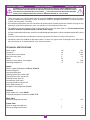
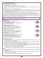
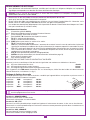
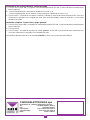
Memorizzazione di ulteriori canali via radio
La memorizzazione può essere anche attivata via radio (senza aprire il contenitore del radioprogrammatore)
se il jumper "J1" è inserito. La segnalazione di quanto avviene è data dall’attivazione del buzzer.
1) Utilizzando un radiocomando in cui almeno uno dei canali sia già stato
memorizzato, attivare il tasto "MR" all’interno del radiocomando.
Nota: Tutti i ricevitori raggiungibili dall'emissione del radiocomando, e
che abbiano almeno un canale del trasmettitore memorizzato, attiveranno
contemporaneamente il buzzer di segnalazione "B1" (fig. 1).
2) Per selezionare il ricevitore in cui memorizzare il nuovo codice attivare uno dei tasti di canale dello stesso
trasmettitore. I ricevitori che non contengono il codice di tale tasto si disattiveranno con l’emissione di un
"bip" lungo 5 secondi; quello invece che contiene il codice emetterà un altro "bip" che dura un secondo,
entrando effettivamente nella modalità di memorizzazione "via radio".
3) Premere il tasto precedentemente scelto sul trasmettitore da memorizzare; a memorizzazione avvenuta il
ricevitore emetterà 2 "bip" di mezzo secondo, dopodiché sarà pronto a memorizzare un altro codice.
4) Per uscire dalla modalità lasciare trascorrere 3 sec. senza memorizzare codici, il ricevitore emetterà un
"bip" lungo 5 sec. ed uscirà dalla modalità.
Quando la memoria viene completamente occupata, il buzzer emetterà 10 "bip" ravvicinati, uscendo
automaticamente dalla modalità di memorizzazione "via radio"; la stessa segnalazione sonora si ottiene
anche ad ogni tentativo di entrare in modalità "via radio" con la memoria interamente occupata.
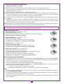
GESTIONE DELLE TASTIERE CON DISPLAY LCD E A LED (fig. 2)
È possibile usare le tastiere MDK RT/MDK RTL per attivare singolarmente o a gruppi più radioprogrammatori;
per fare questo si deve memorizzare sul radioprogrammatore il comando al quale deve rispondere.
Nota: il comando "generale" attiva tutti i dispositivi che abbiano almeno un comando memorizzato.
Memorizzazione di un comando singolo, comando di gruppo
1) Premere e tenere premuto il tasto "P2" sul radioprogrammatore (il LED "L2" lampeggia lentamente)
2) - per il comando singolo: selezionare l'unità con i tasti 4 e 6;
- per il comando di gruppo: premere il tasto 5 e poi selezionare il gruppo con i tasti 4 e 6.
3) Premere il tasto 1, inviando così il comando: il LED "L2" lampeggia 3 volte segnalando l'avvenuta
memorizzazione; se il LED continua a lampeggiare lentamente allora il codice è già in memoria. Per inse-
rire un altro codice ripetere i punti da 1 a 3 dopo aver rilasciato il tasto "P2". Si possono memorizzare al
massimo 4 tastiere.
Cancellazione di un comando singolo, comando di gruppo
1) Premere 2 volte il tasto "P2" e alla seconda attivazione tenerlo premuto (il LED "L2" lampeggia a brevi
impulsi)
2) - per il comando singolo: selezionare l'unità con i tasti 4 e 6;
- per il comando di gruppo: premere il tasto 5 e poi selezionare il gruppo con i tasti 4 e 6.
3) Premere il tasto 1, inviando così il comando: il LED L2 lampeggia 3 volte segnalando l'avvenuta cancella-
zione. Per cancellare un altro codice ripetere i punti da 1 a 3 dopo aver rilasciato il tasto "P2".
Cancellazione completa "comando singolo/gruppo/generale"
1) Premere 2 volte il tasto "P2" e alla seconda attivazione tenerlo premuto (il LED "L2" lampeggia a brevi
impulsi)
2) Premere il tasto 5.
3) Premere il tasto 1, inviando così il comando "generale": il LED "L2" lampeggia 3 volte segnalando l'avve-
nuta cancellazione della tastiera.
Per ulteriori dettagli sulle tastiere LCD/LED si rimanda alle istruzioni del prodotto.
MEMORIZZAZIONE CODICE TX-RX
RCQ449100
13-04-2001
DM0531
Description :
Product Code :
Date :
Drawing number :
P.J.Heath
CARDIN ELETTRONICA S.p.A - 31020 San Vendemiano (TV) Italy - via Raffaello, 36 Tel: 0438/401818 Fax: 0438/401831
Draft :
All rights reserved. Unauthorised copying or use of the information contained in this document is punishable by law
MR

8
• These instructions are aimed at professionally qualified "installers of electrical equipment" and must respect
the local standards and regulations in force. All materials used must be approved and must suit the environment
in which the installation is situated.
• All maintenance operations must be carried out by professionally qualified technicians. Before carrying out any
cleaning or maintenance operations make sure the power is disconnected at the mains.
• This appliance must be used exclusively for the purpose for which it has been made. "i.e. for the command and
control of automatic installations with a 230 Vac power supply".
Any non authorised modifications are to be considered improper dangerous and the complete responsibility of the
installer.
• A correct earth connection is fundamental in order to guarantee the electrical safety of the machine.
• Periodically check the condition of the power cable: If it shows any sign of wear or damage have it replaced by
the manufacturer or an authorised after sales service technician.
TECHNICAL SPECIFICATIONS
Power supply Vac 230
Frequency Hz 50-60
Overall power consumption W 650
Nominal current input A 2,8
Motors Nr. 1
Maximum motor power consumption W 600
Operating temperature °C -20…+55
Inputs
Powers supply binding posts 230 Vac 50-60 Hz
Earth binding post
Antenna binding post
Opening button input contact NO
Closing button input contact NO
Blocking button input NC
Anemometer signal input
Inverting photocells contact NC
Safety edge contact NC
Analogical safety edge input (8.2 kΩ)
Outputs
Power output for 1 motor 600 W
Output powering external devices 24 Vac 7 W
Work time
Maximum programmable time s 180
Pause time
Minimum programmable time s 1
Maximum programmable time s 60
IMPORTANT REMARKS IMPORTANT REMARKS IMPORTANT REMARKS
TO REDUCE THE RISK OF SEVERE INJURY OR DEATH READ THE FOLLOWING REMARKS CARE-
FULLY BEFORE PROCEEDING WITH THE INSTALLATION. PAY PARTICULAR ATTENTION TO ALL
THE PARAGRAPHS MARKED WITH THE SYMBOL . NOT READING THESE IMPORTANT INSTRUC-
TIONS COULD COMPROMISE THE CORRECT WORKING ORDER OF THE SYSTEM.

9
CS1244AB DC0403
Line 230V~
L1
Scheda base
PRG304
10-01-2006
DC0403
Description :
Product Code :
Date :
Drawing number :
P.J.Heath
CARDIN ELETTRONICA S.p.A - 31020 San Vendemiano (TV) Italy - via Raffaello, 36 Tel: 0438/401818 Fax: 0438/401831
Draft :
All rights reserved. Unauthorised copying or use of the information contained in this document is punishable by law
PRG304
6 7
2 3
4
5
Chiusura
Comune
Apertura
M
1
N
L
MAX
C
B
A
MIN
F1
F2
S1
TB
CSP
10 11
13 14 15 16
17 18 19
12
8 9
24Vac
FTC
CSP_A
P2
1 2
ON
D1
20
TA
CMN
TC
CMN
CMN
ANEM
B1
R1
P1
J1
J2
J3
L2
L3
8
1
2
3
6 5 4
7
8
1
2
3
6 5 4
7
2
MDK RT
MDK RTL
1
MOTHER BOARD
Legend
F1 0.5 A rapid action fuse - overload protection 24 Vac circuit
F2 3.15 A rapid action fuse - overload protection 230 Vac circuit
D1 Function selection dip-switch
P1 Work time programming button
P2 Code memorisation/cancellation button
J1 Jumper memorisation via radio
J2 Jumper photoelectric cell function selection
J3 Jumper safety edge function selection
L1 Power on LED
L2 Code management LED
L3 Programming LED
R1 Radio frequency card 433 MHz (S449)
B1 Memorisation via radio buzzer
S1 Torque limiter "Min-A-B-C-Max"
KEYBOARD WITH DISPLAY LCD (MDKRT) OR LED (MDKRTL)

10
ELECTRICAL CONNECTION
• Before connecting the appliance make sure that the voltage and frequency rated on the data plate conform
to those of the mains supply.
WARNING! A double pole trip switch with a least 3 mm between the contacts must be installed between the
unit and the mains supply.
• Connect the control and security device wires.
• Connect the power supply cable to the device.
• Do not use cables with aluminium conductors; do not solder the ends of cables which are to be inserted into
the binding posts; use cables which are marked T min 85°C and are resistant to atmospheric agents.
• The terminal wires must be positioned in such a way that both the wire and the insulating sheath are tightly
fastened (plastic binding is sufficient).
Terminal board connections
1-2 Programmer power supply 230 Vac
3-4-5 Motor command output Closing-Opening-Common
6-7 Power supply/motor earth binding posts
8-9 24 Vac 7 W output, powering external devices
10 TA (NO contact) opening button input
11 TC (NO contact) closing button input
12-13 CMN common for all inputs and outputs
14 TB (NC contact) blocking button input
15 CSP (NC contact) safety edge input. Opening this contact will provoke a travel direction inversion during
the closing stage and block movement during the opening stage (movement will continue the next time
a command is given).
16 FTC (NC contact) security device input ( inverting photocells during closing). The opening of this contact
will provoke a travel direction inversion during closure due to the cutting in of the safety device.
17 CSP_A analogical safety edge input (8.2 kΩ)
18 ANEM anemometer input (see anemometer functions on page 11)
19 Mass for radio receiver antenna
20 Radio receiver antenna pole
ALL UNUSED NC CONTACTS MUST BE BRIDGED
Power up the circuit and make sure that the indicator LEDs are in the following condition:
- L1 Green power on LED ON
- L2 Red transmitter code management LED OFF
- L3 Red time programming LED OFF
If the green power on LED "L1" does not light up check the condition of the fuses and the power cable contacts
at binding posts 1-2 (fig.1).
Setting the torque limiter
The torque can be set to minimum, seeing as the appliance will give a maximum power thrust each time it receives
a movement command
Position "MIN" equals: 120 Vac
Position "A" equals: 145 Vac
Position "B" equals: 170 Vac
Position "C" equals: 195 Vac
Position "MAX" equals: 230 Vac
To set the dip-switches; turn off the power to the programmer, change the settings and then switch the
power back on.
Jumper “REMOTE MEMO”
Inserted: memorization via radio enabled
Deactivated: memorization via radio disabled
Jumper “SEL_FTC”
Inserted: the photocells will impede the activation of the motor if an alarm condition is present
Deactivated: the photocells function as a safety device only while the shutter is closing
Jumper “CSP_A ENABLE”
Inserted: analogical safety edge enabled
Deactivated: analogical safety edge disabled
M
I
N
A
B
C
M
A
X

11
Time programming procedure
- Maximum work time: 180 seconds
- Maximum pause time: 60 seconds
1) Press and hold down button "P1" PROG until LED "L3" lights up.
2) Close the rolling shutter completely using button "P2" MEMO/DEL (this action is carried out in the "manual
mode").
3) Press button "P1" to start the opening manoeuvre.
4) When the rolling shutter arrives at the completely open position and the opening travel limit activates, cutting
off power to the motor, wait 3-4 seconds and then press "P1" again; the LED "L3" will start to flash indicating
that the pause time count has started.
5) The next time you press "P1" the pause time will stop and the rolling shutter will begin to close.
6) When the shutter is completely closed and the closing travel limit activates, cutting off power to the motor, wait
3-4 seconds and then press "P1"; at this point time programming has ended and LED "L3" will switch off.
Note: after activating the programming procedure, step 2 can also be carried out by pressing the button "TC", and
from step 3 onwards you may proceed using the opening button "TA".
Attention! If at the end of time programming the LEDs "L2" and "L3" flash simultaneously the operation was
not successful and you will have to repeat the procedure from step 1.
Function mode
• Semi-automatic (Dip 1 = OFF, Dip 2 = OFF)
- automatic reclosing deactivated
- each transmitter channel works as a sequential command.
Open - Stop - Close - Stop.
• Semi-automatic (Dip 1 = OFF, Dip 2 = ON)
- automatic reclosing deactivated
- the transmitter channels have the following functions:
A - Open - B - Close - C - Stop - D - Sequential.
• Automatic (Dip 1 = ON, Dip 2 = OFF)
- automatic reclosing enabled
- the transmitter channels have the following functions:
A - Open - B - Close - C - Stop - D - Sequential.
• Manual mode (Dip 1 = ON, Dip 2 = ON)
- manual operation during closing.
- the closing photocell "FTC" intervenes blocking the motor
- the sequential command has no effect
- the transmitter channels have the following functions:
A - Open - B - Close - C - Stop - D - No function.
Anemometer functions
•
The anemometer cuts in after the non adjustable threshold of about
35 Km/ora has been reached (measured
using the Cardin anemometro SW01)
• The anemometer only causes closing when the shutter is in movement and blocks the radio transmitter com-
mands for 10 minutes. The terminal board commands are still enabled.
• When the shutter is completely closed or the TB button has been activated the anemometer will be ignored.
• If, during the closing stage (caused by the anemometer) FTC, CSP or CSA cuts in, the system will invert travel
direction until it reaches the completely open position and then:
- close again after five seconds in the presence of wind;
- if automatic closing is enabled the shutter will close again after the programmed pause time has elapsed.
Note:
- Bridging the "TA" and "TC" contacts will transform "TA" into a sequential command with the functions Open-
Stop-Close-Stop.
- The "manual" manoeuvre function can also be obtained by simply keeping the "TA" button (or the "TC" button)
held down for more than one second.
- If a security device is in alarm (stop button or photocell) the LED "L3" will flash quickly.
1
2
1
2
2
1
2
1

12
Remote control
Memorising a channel
1) Press and hold down button "P2": LED "L2" will flash.
2) At the same time activate the transmitter channel to be memorised, "L2" will flash 3 times indicating that the
channel has been memorised; if the LED keeps flashing slowly the channel was already memorised. Only one
channel can be memorised at a time. To insert another channel repeat points 1 and 2 after having released the
button. When the code memory is complete (20 transmitters each with 4 channels memorised) you may only
memorise a new transmitter after you have completely cancelled an existing transmitter (all the buttons) or after
cancelling the entire memory content.
Cancelling a channel
1) Press the button "P2" twice and hold down after pressing the second time: LED "L2" will flash at brief inter-
vals.
2) Activate the transmitter channel to be cancelled until the LED flashes 3 times.
To cancel another channel repeat points 1 and 2 after having released the button.
Cancelling the entire memory content
Press "P2" three times and hold down after pressing the third time. During the cancellation procedure (3-4 seconds)
LED "L2" remains lit.
After cancellation the LED will flash 3 times; at this point release the button.
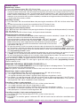
Memorising ulterior channels via radio
• Memorisation can be activated via radio (without opening the receiver container) if jumper "J1" has been
inserted. Activation will be indicated by the buzzer sounding.
1) Using a transmitter, in which at least one channel button "A,B,C or D" has already
been memorised in the receiver, press the button "MR" as shown in the figure.
Note: all the receivers within range when the channel button is pressed (and which
have at least one of the transmitter channel buttons memorised) will activate their
signal buzzer "B1" (fig. 1).
2) To select the receiver in which to memorise the new code activate one of the channels on the same transmit-
ter. The receivers which do not contain that channel code will sound a five-second long "beep" and will then
deactivate. The receivers which contain the channel code will sound a one-second long "beep" and will enter
the "programming via radio" mode.
3) Press the channel buttons on the pre-selected transmitter that you wish to memorise; the receiver will sound
2 "beeps" of half a second each after which the receiver will be ready to receive another code.
4) To leave the programming mode wait for 3 seconds without memorising any codes. The receiver will sound a
five-second long "beep" and will then exit the programming mode.
When the memory is entirely occupied the buzzer will sound 10 rapid "beeps" and will automatically leave the
"programming via radio" mode. The same signal is given each time you try to enter "programming via radio"
when the memory is full.
MANAGING THE DISPLAY KEYBOARD LCD AND LED (fig. 2)
It is possible to use the MDK RT/MDK RTL to activate single or groups of radio programmers: The command will
have to be memorised in the radio programmer.
Note: the "general" command will activate all devices that have at least one command memorised.
Memorising a single or group command)
1) Press and hold down button "P2" on the radio programmer (LED "L2" will flash slowly).
2) - for a single command: select the unit using buttons 4 and 6;
- for a group command: press button 5 and then select the group using buttons 4 and 6.
3) Press button 1 to send the command: LED "L2" will flash 3 times to confirm memorisation; if the LED contin-
ues to flash slowly the code is already stored in memory. To insert another code repeat points 1 to 3 after first
releasing button "P2". Up to 4 keyboards can be memorised.
Cancelling a single or group command
1) Press button "P2" twice and hold down (LED "L2" will flash at brief intervals).
2) - for a single command: select the unit using buttons 4 and 6;
- for a group command: press button 5 and then select the group using buttons 4 and 6.
3) Press button 1 to send the command: LED "L2" will flash 3 times to confirm cancellation. To insert another
code repeat points 1 to 3 after first releasing button "P2".
Cancelling everything "single command/group/general"
1) Press button "P2" twice and hold down (LED "L2" will flash at brief intervals)
2) Press button 5.
3) Press button 1 to send the "general" command: LED "L2" will flash 3 times to confirm the cancellation of the
keyboard.
For more information regarding the LCD/LED keyboards see the instructions supplied with the product.
MEMORIZZAZIONE CODICE TX-RX
RCQ449100
13-04-2001
DM0531
Description :
Product Code :
Date :
Drawing number :
P.J.Heath
CARDIN ELETTRONICA S.p.A - 31020 San Vendemiano (TV) Italy - via Raffaello, 36 Tel: 0438/401818 Fax: 0438/401831
Draft :
All rights reserved. Unauthorised copying or use of the information contained in this document is punishable by law
MR

13
• Ce livret est destiné à des personnes titulaires d'un certificat d'aptitude professionnelle pour l'ins-
tallation des "APPAREILS ÉLECTRIQUES" et requiert une bonne connaissance de la technique
appliquée professionnellement, ainsi que des normes en vigueur. Les matériels utilisés doivent être
certifiés et être adaptés aux conditions atmosphériques du lieu d'implantation.
• Les travaux de maintenance ne doivent être effectués que par un personnel qualifié. Avant une
quelconque opération de nettoyage ou de maintenance, mettre l'appareil hors tension.
• Les appareils décrits dans le présent livret ne doivent être destinés qu’à l’utilisation pour laquelle
ils ont été expressément conçus, c’est-à-dire pour la commande et le contrôle d’installations
automatiques avec motorisation 230 Vac.
• Une diverse utilisation des produits ou leur destination à un usage différent de celui prévu et/ou
conseillé n'a pas été expérimentée par le Constructeur. Par conséquent, les travaux effectués sont
entièrement sous la responsabilité de l'installateur.
• Pour garantir la sécurité électrique, il est impératif de brancher correctement l’appareil à la prise de
terre.
• Contrôler périodiquement l’état du câble d’alimentation. S’il présente des traces d’usure et/ou d’en-
dommagement, il doit être remplacé par le fabricant ou par son service d’assistance technique.
CARACTÉRISTIQUES TECHNIQUES
Alimentation Vac 230
Fréquence Hz 50-60
Puissance totale W 650
Courant nominal A 2,8
Moteurs pouvant être branchés Nbre 1
Puissance maxi. du moteur W 600
Température de fonctionnement °C -20…+55
Entrées
Branchement alimentation 230 Vac 50-60 Hz
Borne de terre
Branchement de l’antenne
Entrée N.O. touche d’ouverture
Entrée N.O. touche de fermeture
Entrée N.F. touche de blocage
Entrée signal anémomètre
Contact N.F. cellules photoélectriques d’inversion
Contact N.F. bord de protection
Entrée pour bord de protection analogique (8.2 kΩ)
Sorties
Sortie pour 1 moteur puissance 600 W
Sortie pour alimentation dispositifs extérieurs 24 Vac 7 W
Temps de travail
Temps maximum programmable sec. 180
Temps d’arrêt
Temps minimum programmable sec. 1
Temps maximum programmable sec. 60
CONSIGNES IMPORTANTES! CONSIGNES IMPORTANTES! CONSIGNES IMPORTANTES!
POUR RÉDUIRE LES RISQUES DE BLESSURES GRAVES OU DE MORT, LIRE ATTENTIVEMENT
LES CONSIGNES SUIVANTES AVANT DE PROCÉDER À LA POSE. PRÊTER GRANDE ATTENTION
À TOUTES LES SIGNALISATIONS QUI SE TROUVENT DANS LE TEXTE. LE NON RESPECT
DE CES CONSIGNES POURRAIT COMPROMETTRE LE BON FONCTIONNEMENT DU SYSTÈME.

14
CS1244AB DC0403
Line 230V~
L1
Scheda base
PRG304
10-01-2006
DC0403
Description :
Product Code :
Date :
Drawing number :
P.J.Heath
CARDIN ELETTRONICA S.p.A - 31020 San Vendemiano (TV) Italy - via Raffaello, 36 Tel: 0438/401818 Fax: 0438/401831
Draft :
All rights reserved. Unauthorised copying or use of the information contained in this document is punishable by law
PRG304
6 7
2 3
4
5
Chiusura
Comune
Apertura
M
1
N
L
MAX
C
B
A
MIN
F1
F2
S1
TB
CSP
10 11
13 14 15 16
17 18 19
12
8 9
24Vac
FTC
CSP_A
P2
1 2
ON
D1
20
TA
CMN
TC
CMN
CMN
ANEM
B1
R1
P1
J1
J2
J3
L2
L3
8
1
2
3
6 5 4
7
8
1
2
3
6 5 4
7
2
MDK RT
MDK RTL
1
CARTE DE BASE
Nomenclature
F1 Fusible 0.5 A rapide - protection contre les surcharges 24 Vac
F2 Fusible 3.15 A rapide - protection contre les surcharges 230 Vac
D1 Dip-switch sélection des fonctions
P1 Bouton de programmation des temps
P2 Bouton de mémorisation/effacement des codes émetteurs
J1 Cavalier de validation pour la mémorisation via radio
J2 Cavalier fonction cellules photoélectriques
J3 Cavalier fonction bord de protection analogique 8.2 kΩ
L1 Led carte sous tension
L2 Led gestion des codes émetteurs
L3 Led programmation
R1 Module RF 433 MHz (S449)
B1 Avertisseur sonore pour signalisation mode "via radio"
S1 Régulateur de couple "Min.-A-B-C-Maxi."
ÉMETTEUR MURAL AVEC AFFICHEUR LCD (MDKRT) OU LED (MDKRTL)

15
BRANCHEMENT ÉLECTRIQUE
• Avant d’effectuer le branchement électrique, contrôler que le tension et la fréquence indiquées sur la plaquette
signalétique correspondent aux données du réseau d’alimentation électrique.
Attention! Entre la centrale de commande et le réseau doit être interposé un interrupteur omnipolaire avec
ouverture des contacts d’au moins 3 mm.
• Brancher les fils des commandes et ceux qui proviennent des dispositifs de sécurité.
• Après quoi, brancher le câble d’alimentation au dispositif.
• Ne pas utiliser de câble avec conducteurs en aluminium; ne pas étamer l’extrémité des fils à brancher sur le
bornier; utiliser un câble marqué T min. 85°C et résistant aux agents atmosphériques.
• Les conducteurs devront être adéquatement fixés à proximité du bornier. Cette fixation devra bloquer tant l’isola-
tion que le conducteur (il suffit d’un collier).
Branchements du bornier
1-2 Alimentation générale 230 Vac
3-4-5 Sortie commande du moteur Fermeture-Ouverture-Commun
6-7 Entrée terre pour alimentation et moteur
8-9 Sortie 24 Vac 7 W alimentation des dispositifs externes
10 TA (N.O.) entrée touche d'ouverture.
11 TC (N.O.) entrée touche de fermeture.
12-13 CMN Commun pour toutes les entrées et les sorties.
14 TB (N.F.) entrée touche de blocage.
15 CSP (N.F.) entrée pour bord de protection. L’ouverture de ce contact inverse le sens de marche dans la phase de
fermeture et interrompt la manœuvre dans la phase d’ouverture (la manœuvre reprend à la commande suivante).
16 FTC (N.F.) entrée pour dispositifs de sécurité (cellule photoélectrique d’inversion du sens de marche en ferme-
ture). L'ouverture de ce contact, suite à l’intervention des dispositifs de sécurité, durant la phase de fermeture,
provoquera une inversion de la manœuvre.
17 CSP_A entrée pour bord de protection analogique 8.2 kΩ
18 ANEM entrée pour anémomètre (voir fonctionnement de l’anémomètre page 16)
19 Masse antenne récepteur radio
20 Âme antenne récepteur radio
N.B: FAIRE UN PONT SUR TOUS LES CONTACTS N.F. INUTILISÉS.
Alimenter le circuit et contrôler que l'état des leds de signalisation soit conforme aux indications ci-dessous:
- L1 LED verte d’alimentation du circuit allumée
- L2 LED rouge de gestion des codes émetteurs éteinte
- L3 LED rouge de signalisation bouton de programmation temps éteinte
Dans l’hypothèse où la LED verte d’alimentation "L1" ne s’allumerait pas, vérifier l’état des fusibles et le branchement du
câble d’alimentation sur les bornes 1-2 (fig.1).
Réglage du limiteur de couple
Le couple peut être réglé sur les valeurs minimales, considéré que l'appareil délivre une impulsion en puissance maxi. à
chaque commande de manœuvre interceptée.
La position "MIN." correspond à: 120 Vac
La position "A" correspond à: 145 Vac
La position "B" correspond à: 170 Vac
La position "C" correspond à: 195 Vac
La position "MAXI" correspond à: 230 Vac
Pour la configuration des dip-switches/cavalier: mettre le programmateur hors tension, modifier leur position et remettre
ensuite le programmateur sous tension.
Cavalier J1 “REMOTE MEMO”
Connecté: mémorisation via radio validée
Déconnecté: mémorisation via radio invalidée
Cavalier J2 “SEL_FTC”
Connecté: les cellules photoélectriques empêchent également l’actionnement du moteur, si elles sont en état d’alarme.
Déconnecté: les cellules photoélectriques interviennent seulement comme protection quand le rideau à enroulement est
dans la phase de fermeture
.
Cavalier J3 “CSP_A ENABLE”
Connecté: bord de sécurité analogique invalidé
Déconnecté: bord de sécurité analogique validé
M
I
N
A
B
C
M
A
X

16
Procédé de programmation des temps
- Temps de travail maxi: 180 secondes
- Temps de pause maxi: 60 secondes
1) Appuyer sur la touche "P1" PROG et la maintenir appuyée jusqu’à ce que la LED "L3" s’allume.
2) Fermer complètement le rideau à enroulement au moyen de la touche "P2" MEMO/DEL (l’actionnement s’effectue en
mode de fonctionnement manuel).
3) Appuyer sur la touche "P1" pour lancer la manœuvre d’ouverture.
4) Quand le rideau à enroulement arrive en position d’ouverture complète; et le fin de course en ouverture s’active, ce
qui coupe l’alimentation au moteur et le bloque, attendre 3-4 s, et ensuite appuyer de nouveau sur "P1": la LED "L3"
se met alors à clignoter pour signaler le début du comptage du temps de pause.
5) La pression suivante sur la touche "P1" met fin au comptage du temps de pause et le rideau à enroulement commence
à se fermer.
6) Quand le rideau à enroulement arrive en position de fermeture complète, et le fin de course en fermeture s’active, ce
qui coupe l’alimentation au moteur, attendre 3-4 sec, et ensuite appuyer de nouveau sur la touche "P1". À ce point,
la programmation des temps se termine, et la LED "L3" s’éteint.
Nota: après avoir activé le procédé de programmation, l’opération de l’étape 2 peut aussi être effectuée en appuyant sur
la touche "TC", et celles à partir de l’étape 3 en appuyant sur la touche d’ouverture "TA".
Attention! Si à l’issue de la programmation, les LED "L2" et "L3" clignotent simultanément, le procédé ne s’est pas
conclu correctement, et il faudra refaire la programmation à partir de l’étape 1.
Modes de fonctionnement
• Semi-automatique (Dip 1 = OFF, Dip 2 = OFF)
- refermeture automatique invalidée
- chaque touche de l’émetteur est affectée à la fonction de commande séquentielle.
Ouverture - Blocage - Fermeture - Blocage.
• Semi-automatique (Dip 1 = OFF, Dip 2 = ON)
- refermeture automatique invalidée
- les touches de canal de l’émetteur sont affectées à la fonction:
A - Ouverture - B - Fermeture - C - Blocage - D - Séquentielle.
• Automatique (Dip 1 = ON, Dip 2 = OFF)
- refermeture automatique validée
- les touches de canal de l’émetteur sont affectées à la fonction:
A - Ouverture - B - Fermeture - C - Blocage - D - Séquentielle.
• Manuel (homme mort) (Dip 1 = ON, Dip 2 = ON)
- mode de fonctionnement manuel en fermeture
- les sécurités "FTC" fonctionnent comme dispositifs de blocage en fermeture
- la commande séquentielle n’est pas acceptée
- les touches de canal de l’émetteur sont affectées à la fonction:
A - Ouverture - B - Fermeture - C - Blocage - D - Sans fonction.
Fonctionnement de l’anémomètre
• L’anémomètre intervient à une vitesse non sélectionnable d’environ 35 Km/heure (avec anémomètre Cardin SW01).
• L’anémomètre lance la fermeture seulement si le rideau est arrêté et empêche les commandes via radio pendant 10
minutes. Les commandes sur le bornier sont encore validées.
• Avec rideau complètement fermé ou bouton TB activé, l’anémomètre est ignoré.
• Pendant la phase de fermeture (lancée par l’anémomètre), si FTC, CSP ou CSA intervient, le système inverse le sens
de marche jusqu’à l’ouverture complète, et ensuite:
- s’il y a du vent, il le referme après un temps maxi. de 5 sec.,
- si la refermeture automatique est validée, il le referme après le temps de pause programmé.
Nota:
- En faisant un pont entre l’entrée "TA" et l’entrée "TC", on transforme l’entrée "TA" en commande séquentielle avec
fonction Ouvre-Stop-Ferme-Stop.
- Il est également possible de lancer la manœuvre en manuel (Homme Mort) tout simplement en maintenant appuyée la
touche "TA" (ou la touche "TC") pendant plus d’une seconde.
- Si un quelconque dispositif de sécurité est en état d’alarme (touche de blocage ou cellule photoélectrique), la LED "L3"
clignote rapidement.
1
2
1
2
2
1
2
1

17
Commande via radio
Mémorisation d’un canal
1) Appuyer sur la touche "P2" et la maintenir appuyée: la LED "L2" se met à clignoter lentement.
2) Activer simultanément l'émetteur sur le canal à mémoriser; la LED "L2" clignote 3 fois pour signaler que le canal a été
mémorisé. Si la LED continue à clignoter lentement, le canal a déjà été mémorisé précédemment. Il est possible de mémo-
riser qu’un seul canal à la fois. Pour introduire un autre canal, répéter les étapes 1 et 2 après avoir relâché la touche. Quand
la mémoire des codes est pleine (20 émetteurs à 4 touches de mémorisés), il est possible de mémoriser un nouvel émetteur
à condition d’en effacer complètement (toutes les touches) un qui se trouve en mémoire, ou toute la mémoire.
Effacement d’un canal
1) Appuyer deux fois de suite sur la touche "P2"; à la deuxième pression, maintenir la touche appuyée. La LED "L2" se met
alors à clignoter lentement.
2) Activer l’émetteur sur le canal à effacer jusqu’à ce que la LED clignote trois fois.
Répéter les opérations des étapes 1 et 2 pour effacer d’autres canaux, après avoir relâché la touche.
Effacement total de la mémoire
Appuyer trois fois de suite sur la touche "P2"; à la troisième pression, maintenir la touche appuyée. Pendant le procédé d’effa-
cement (3-4 secondes), la LED “L2” reste allumée. À la fin de l’effacement, la LED clignote 3 fois; relâcher alors la touche.
Mémorisation par radio d’autres canaux
La mémorisation peut aussi être activée par radio (sans devoir ouvrir le radio programmateur) si le cavalier "J1" est connecté.
Les différentes tonalités émises par l’avertisseur sonore donneront une indication claire sur ce qui se produira.
1) Utiliser une télécommande dont au moins un des canaux a déjà été mémorisé, et activer la
touche "MR" à l’intérieur de la télécommande.
Nota: tous les récepteurs qui se trouvent dans le rayon d'action de la télécommande et qui
ont au moins un canal de l'émetteur de mémorisé, enclencheront simultanément l'avertis-
seur sonore "B1" (fig. 1).
2) Pour sélectionner le récepteur dans lequel il faut mémoriser le nouveau code, activer une des touches de canal de ce même
émetteur. Les récepteurs qui ne contiennent pas le code de cette touche se désactiveront, ce qui est signalé par un bip de
5 secondes. Par contre, le récepteur contenant le code émettra un bip différent qui dure 1 seconde signalant l’accès effectif
au procédé de mémorisation "par radio".
3) Appuyer sur la touche de canal choisie précédemment sur l’émetteur à mémoriser. Le récepteur signalera que la mémori-
sation a eu lieu en émettant 2 bips d’une demi-seconde. Après quoi, le récepteur sera prêt à mémoriser un autre code.
4) Pour quitter le procédé de mémorisation "par radio", laisser passer 3 secondes sans mémoriser de codes. Le récepteur
émettra un bip de 5 secondes et quittera le procédé.
Lorsque la mémoire est pleine, le buzzer émet 10 bips très courts, et on sort automatiquement du procédé de mémorisation
"via radio". En outre, l'avertisseur sonore émettra le même signal sonore chaque fois qu’on essaiera d’accéder au procédé de
mémorisation "via radio" avec mémoire pleine.
GESTION DES ÉMETTEURS MURAUX AVEC AFFICHEUR LCD ET À LED (fig. 2)
Il est possible d’utiliser les émetteurs muraux MDK RT/MDK RTL pour activer individuellement ou en groupes plusieurs radio-
programmateurs. Pour ce faire, il faut mémoriser sur le radioprogrammateur la commande à laquelle il doit répondre. Note: la
commande "générale" active tous les dispositifs qui ont au minimum une commande de mémorisée.
Mémorisation d’une commande individuelle et d’une commande de groupe
1) Appuyer sur la touche "P2" sur le radioprogrammateur et la maintenir appuyée (la LED "L2" clignote lentement).
2) - pour la commande individuelle: sélectionner l’unité au moyen des touches 4 et 6,
- pour la commande de groupe: appuyer sur la touche 5 et ensuite sélectionner le groupe au moyen des touches 4 et 6.
3) Appuyer sur la touche 1 pour délivrer la commande; la LED "L2" clignote trois fois, ce qui signale que la mémorisation a eu
lieu. Si la LED continue à clignoter lentement, le code a déjà été mémorisé. Pour entrer un autre code, répéter les étapes 1,
2 et 3 après avoir relâché la touche "P2". Il est possible de mémoriser au maximum 4 émetteurs muraux.
Annulation d’une commande individuelle et d’une commande de groupe
1) Appuyer 2 fois de suite sur la touche "P2" et la maintenir appuyée à la deuxième pression (la LED "L2" clignote rapide-
ment).
2) - pour la commande individuelle: sélectionner l’unité au moyen des touches 4 et 6,
- pour la commande de groupe: appuyer sur la touche 5 et ensuite sélectionner le groupe au moyen des touches 4 et 6.
3) Appuyer sur la touche 1 pour délivrer la commande; la LED L2 clignote trois fois, ce qui signale que l’annulation a eu lieu.
Pour annuler un autre code, répéter les étapes 1, 2 et 3 après avoir relâché la touche "P2".
Annulation complète "commande individuelle, de groupe et générale"
1) Appuyer deux fois de suite sur la touche "P2" et la maintenir appuyée à la deuxième pression (la LED "L2" clignote rapide-
ment).
2) Appuyer sur la touche 5.
3) Appuyer sur la touche 1 pour délivrer la commande "générale"; la LED "L2" clignote 3 fois, ce qui signale que l’annulation
a eu lieu.
Pour plus de détails sur les émetteurs muraux à LCD/LED, consulter les notices de ces produits.
MEMORIZZAZIONE CODICE TX-RX
RCQ449100
13-04-2001
DM0531
Description :
Product Code :
Date :
Drawing number :
P.J.Heath
CARDIN ELETTRONICA S.p.A - 31020 San Vendemiano (TV) Italy - via Raffaello, 36 Tel: 0438/401818 Fax: 0438/401831
Draft :
All rights reserved. Unauthorised copying or use of the information contained in this document is punishable by law
MR

18
• Das vorliegende Handbuch wendet sich an Personen, die zur Installation von "Elektrogeräten" befähigt sind
und setzt gute technische Kenntnisse und die Kenntnis der geltenden Vorschriften voraus.
Die verwendeten Materialien müssen zertifiziert sein und für die Umweltbedingungen der Installation geeignet
sein.
• Die Wartungsarbeiten müssen von qualifiziertem Fachpersonal ausgeführt werden. Bevor irgendwelche Säube-
rungs- oder Wartungsarbeiten ausgeführt werden, ist die Apparatur vom Stromnetz zu trennen.
• Die hier beschriebenen Apparaturen sind nur für den Zweck bestimmt, für den sie ausdrücklich konzipiert worden
sind: „Die Befehlung und Steuerung von automatisierten Installationen mit 230-Vac-Motoren“.
Die Anwendung und Nutzung der Produkte zu einem anderen Zweck, als es vorgesehen und/oder geraten
wurde, ist nicht vom Hersteller erprobt worden. Die Installationsarbeiten erfolgen daher unter der vollständigen
Verantwortung des Installateurs.
• Die Güte des Erdungsanschlusses der Apparatur ist fundamental für die Sicherheit der Elektrik.
• Die Unversehrtheit des Stromversorgungskabels sollte in regelmäßigen Abständen überprüft werden. Wenn
daran Zeichen von Verschleiß und/oder Beschädigungen erkennbar sind, muss es vom Hersteller oder von
dessen technischen Kundendienst ausgewechselt werden.
TECHNISCHE DATEN
Stromversorgung Vac 230
Frequenz Hz 50-60
Gesamtleistung W 650
Nennstrom A 2,8
Anschließbare Motoren Nr. 1
Maximale Motorleistung W 600
Betriebstemperatur °C -20…+55
Eingänge
Anschluss Stromversorgung 230 Vac 50-60 Hz
Erdungsklemme
Antennenanschluss
Eingang N.O.-Kontakt Öffnungstaste
Eingang N.O.-Kontakt Schließtaste
Eingang N.C.-Kontakt Stoptaste
Eingang Windmessersignal
N.C.-Kontakt Umkehrungslichtschranke
N.C.-Kontakt Sicherheitsleiste
Eingang für analogische Sicherheitsleiste (8.2 kΩ)
Ausgänge
Ausgang für 1 Motor, Leistung 600 W
Ausgang für die Versorgung der externen Vorrichtungen 24 Vac 7 W
Arbeitszeit
Maximale programmierbare Zeit Sek. 180
Pausenzeit
Kürzeste programmierbare Zeit Sek. 1
Maximale programmierbare Zeit Sek. 60
WICHTIGE HINWEISE WICHTIGE HINWEISE WICHTIGE HINWEISE
ZUR VERRINGERUNG DER VERLETZUNGS- ODER TODESGEFAHR SOLLTEN DIE NACHSTEHENDEN
HINWEISE VOR DER INSTALLATION AUFMERKSAM GELESEN WERDEN. BESONDERE AUFMERK-
SAMKEIT SOLLTE ALLEN IM TEXT BEFINDLICHEN HINWEISEN GESCHENKT WERDEN. DEREN
NICHTBEACHTUNG KÖNNTE DEN ORDENTLICHEN BETRIEB DES SYSTEMS BEEINTRÄCHTIGEN.

19
CS1244AB DC0403
Line 230V~
L1
Scheda base
PRG304
10-01-2006
DC0403
Description :
Product Code :
Date :
Drawing number :
P.J.Heath
CARDIN ELETTRONICA S.p.A - 31020 San Vendemiano (TV) Italy - via Raffaello, 36 Tel: 0438/401818 Fax: 0438/401831
Draft :
All rights reserved. Unauthorised copying or use of the information contained in this document is punishable by law
PRG304
6 7
2 3
4
5
Chiusura
Comune
Apertura
M
1
N
L
MAX
C
B
A
MIN
F1
F2
S1
TB
CSP
10 11
13 14 15 16
17 18 19
12
8 9
24Vac
FTC
CSP_A
P2
1 2
ON
D1
20
TA
CMN
TC
CMN
CMN
ANEM
B1
R1
P1
J1
J2
J3
L2
L3
8
1
2
3
6 5 4
7
8
1
2
3
6 5 4
7
2
MDK RT
MDK RTL
1
ELEKTRONISCHE PLATINE
Zeichenerklärung
F1 Sicherung 0.5 A flink - Überlastungsschutz 24 Vac
F2 Sicherung 3.15 A flink - Überlastungsschutz 230 Vac
D1 Dip-Schalter Funktionenwahl
P1 Taste zur Programmierung der Zeiten
P2 Speicher-/Löschtaste des Sendercodes
J1 Überbrückung Sendercode-Speicherungsfreigabe über Funk
J2 Überbrückung zur Wahl der Funktionsweise der Lichtschranke
J3 Überbrückung Funktionsweise der analogische Leiste 8.2 kΩ
L1 LED Schaltkreiskarten-Stromversorgung
L2 LED Sender-Code Verwaltung
L3 LED Programmierung
R1 RF-Modul 433 MHz für Sender S449
B1 Meldesummer für "Funk"-Modus
S1 Drehmomentregler "Min - A - B - C - Max"
ZEITSCHALTUHR MIT DISPLAY LCD (MDKRT) ODER LED (MDKRTL)

20
M
I
N
A
B
C
M
A
X
ELEKTROANSCHLUSS
• Vor der Ausführung des Elektroanschlusses sicherstellen, dass die auf dem Typenschild angegebene Spannung und
Frequenz mit denen der elektrischen Stromversorgung übereinstimmen.
Achtung! Zwischen der Steuereinheit und dem Stromversorgungsnetz muss ein allpoliger Schalter mit einem
Kontaktenabstand von mindestens 3 mm zwischengeschaltet werden.
• Die Drähte der Steuereinheit und der Sicherheitsvorrichtungen anschließen.
• Das Stromkabel an das Gerät anschließen.
• Keine Leitungen mit Aluminiumleiter verwenden; in die Klemmleiste einzuführende Kabelenden nicht verzinnen; Kabel
mit der Markierung "T min. 85°C - wetterbeständig" verwenden.
• Die Leitungen müssen in der Nähe der Klemmleiste in angemessener Weise so befestigt werden, dass sowohl die
Isolierung als auch der Leiter befestigt wird (Kabelband genügt).
Anschlüsse auf der Klemmleiste
1-2 Hauptstromversorgung 230 Vac
3-4-5 Ausgang Steuerung des motors Schließen/Öffnen/Gemein
6-7 Erdungseingang für Stromversorgung und Motor
8-9 Ausgang 24 Vac 7 W Versorgung für externe Vorrichtungen
10 TA (N.O.-Kontakt) Eingang Öffnungstaste
11 TC (N.O.-Kontakt) Eingang Schließtaste
12-13 CMN Neutral für alle Eingänge und Ausgänge
14 TB (N.C.-Kontakt) Eingang Stoptaste
15 CSP (N.C.-Kontakt) für Sicherheitsleiste. Das Öffnen des Kontaktes verursacht die Bewegungsumkehrung während
der Schließung und unterbricht die Bewegung während der Öffnung (die Bewegung wird beim nachfolgenden
Befehlseingang wieder aufgenommen).
16 FTC (N.C.-Kontakt) für Sicherheitsvorrichtungen (Lichtschranke für Bewegungsumkehrung beim Schließen). Das
Öffnen des Kontaktes infolge des Eingreifens der Sicherheitsvorrichtungen während des Schließens verursacht
die Bewegungsumkehrung.
17 CSP_A (N.C.-Kontakt) Eingang analogische Sicherheitsleiste (8.2 kΩ)
18 ANEM Eingang Windmesser (siehe Windmesserbetriebsweise auf Seite 21)
19 Außenleiter Funkempfängerantenne
20 Innenleiter Funkempfängerantenne
HINWEIS: ALLE NICHTBENUTZTEN N.C.-KONTAKTE MÜSSEN ÜBERBRÜCKT WERDEN.
Den Schaltkreis mit Strom versorgen und prüfen, ob der Zustand der Anzeige-LED wie nachstehend bezeichnet ist:
- L1 grüne LED Leiterplatten-Stromversorgung leuchtet
- L2 rote LED Sendercode-Programmierung erloschen
- L3 rote LED Zeitenprogrammierungsverfahren erloschen
Falls sich die grüne LED “L1” der Stromversorgung nicht einschaltet, den Zustand der Sicherungen und den Anschluss
des Stromkabels zwischen den Klemmen 1-2 (Abb. 1) überprüfen.
Einstellung des Drehmomentbegrenzers
Der Drehmoment kann auf Mindestwerte eingestellt werden, da das Gerät einen Impuls
bei maximaler Leistung bei jedem empfangenen Bewegungsbefehl abgibt.
Stellung "MIN" entspricht: 120 Vac
Stellung "A" entspricht: 145 Vac
Stellung "B" entspricht: 170 Vac
Stellung "C" entspricht: 195 Vac
Stellung "MAX" entspricht: 230 Vac
Zur Einstellung der Dip-Schalter/Jumper: Stromversorgung des Programmierers unterbrechen, Einstellungen ändern,
Stromversorgung wieder einschalten.
Überbrückung J1 “REMOTE MEMO”
Eingesetzt: Speicherung über Funk freigegeben
Nicht eingesetzt: Speicherung über Funk gesperrt
Überbrückung J2 “SEL_FTC”
Eingesetzt: Die Lichtschranken verhindern wenn in Alarmstellung auch das Einschalten des Motors.
Nicht eingesetzt: Die Lichtschranken dienen zum Schutz nur während der Schließphase des Rollladens.
Überbrückung J3 “CSP_A ENABLE”
Eingesetzt: Analogische Sicherheitsleiste abgeschaltet
Nicht eingesetzt: Analogische Sicherheitsleiste eingeschaltet
La pagina si sta caricando...
La pagina si sta caricando...
La pagina si sta caricando...
La pagina si sta caricando...
La pagina si sta caricando...
La pagina si sta caricando...
La pagina si sta caricando...
La pagina si sta caricando...
-
 1
1
-
 2
2
-
 3
3
-
 4
4
-
 5
5
-
 6
6
-
 7
7
-
 8
8
-
 9
9
-
 10
10
-
 11
11
-
 12
12
-
 13
13
-
 14
14
-
 15
15
-
 16
16
-
 17
17
-
 18
18
-
 19
19
-
 20
20
-
 21
21
-
 22
22
-
 23
23
-
 24
24
-
 25
25
-
 26
26
-
 27
27
-
 28
28


Cardin PRG micro 230 Vac Manuale del proprietario
- Tipo
- Manuale del proprietario
- Questo manuale è adatto anche per
in altre lingue
Altri documenti
-
 Ferrox Loopbrug "Opvouwbaar" Manuale utente
-
Nice Automation MC200 Guida d'installazione
-
-
Genius Anemometer Istruzioni per l'uso
-
-
 MO-EL 9001 Manuale del proprietario
-
Erone SEL2681R868-P4 Use And Installation Manual
-
JCM Micro-DCS Guida utente
-
-

