
OPERATOR’S MANUAL
VOLVO PENTA IPS 350/400/450/500/600

CALIFORNIA
Proposition 65 Warning
Diesel engine exhaust and some of its constituents are known
to the State of California to cause cancer, birth defects, and
other reproductive harm.
Diese Betriebsanleitung ist auch auf
Deutsch erhältlich.
Ein Bestellcoupon ist am Ende der Betriebs-
anleitung zu finden.
Ce manuel d’instructions peut être
commandé en français.
Vous trouverez un bon de commande à la fin
du manuel d’instructions.
Este libro de instrucciones puede soli-
citarse en español.
El cupón de pedido se encuentra al final del
libro.
Den här instruktionsboken kan bestäl-
las på svenska.
Beställningskupong finns i slutet av instrukti-
onsboken.
Questo manuale d’istruzioni può esse-
re ordinato in lingua italiana.
Il tagliando per l’ordinazione è riportato alla
fine del manuale.
Dit instructieboek kan worden besteld
in het Nederlands.
De bestelcoupon vindt u achter in het instruc-
tieboek.
Denne instruktionsbog kan bestilles på
dansk.
Bestillingskupon findes i slutningen af in-
struktionsbogen.
Tämän ohjekirjan voi tilata myös suo-
menkielisenä.
Tilauskuponki on ohjekirjan lopussa.
Este manual de instruções pode ser
encomendado em português.
O talão de requerimento encontra-se no fim
do manual.
Áõôü ôï åã÷åéñßäéï ÷ñÞóçò äéáôßèåôáé
óôçí áããëéêÞ ãëþóóá.
Ãéá íá ðáñáããåßëåôå Ýíá áíôßôõðï,
óõìðëçñþóôå ôç öüñìá ðïõ âñßóêåôáé óôï
ôÝëïò áõôïý ôïõ åã÷åéñéäßïõ ÷ñÞóçò.
Bu kullanýcý el kitabý Türkçe
dillerinde mevcuttur.
Birnüshasýný sipariþ etmek için kullanýcý el
kitabýnýn sonundaki formu doldurun.
ƒ‡ÌÌÓ ÛÍÓ‚Ó‰ÒÚ‚Ó ÓÔ‡ÚÓ‡
ËÏÂÂÚÒˇ ̇ ÚÛˆÍÓÏ Ë ÛÒÒÍÓÏ
ˇÁ˚͇ı.
ƒÎˇ ÔÓÎÛ˜ÂÌˡ ËÌÒÚÛ͈ËË Ì‡ ÌÛÊÌÓÏ
ˇÁ˚Í Á‡ÔÓÎÌËÚ ÙÓÏÛ ‚ ÍÓ̈Â
ËÌÒÚÛ͈ËË.
This operator’s manual is available in
English.
Complete the form at the end of the opera-
tor’s manual to order a copy.

Welcome aboard
Volvo Penta marine engines are used all over the world. They are used in all possible operating
conditions for professional as well as leisure purposes. That’s not surprising.
After 100 years as an engine manufacturer the Volvo Penta name has become a symbol of reli-
ability, technical innovation, top of the range performance and long service life. We also believe
that this is what you demand and expect of your Volvo Penta engine.
We would like you to read this operator’s manual thoroughly and consider the advice we give on
operation and maintenance before your maiden voyage so that you will be ensured of fulfilling
your expectations. Please pay attention to the safety instructions contained in the manual.
As owner of a Volvo Penta marine engine, we would also like to welcome you to a worldwide
network of dealers and service workshops to assist you with technical advice, service require-
ments and replacement parts. Please contact your nearest authorized Volvo Penta dealer for
assistance.
We also invite you to visit our home page on the Internet at www.volvopenta.com
With warm regards
AB VOLVO PENTA

Safety Information ............................................. 3-7
General ................................................................... 3
Boat travel............................................................... 4
Maintenance and service ....................................... 6
Introduction .................................................... 8-11
Running-in ............................................................. 8
Fuel and oil types .................................................. 8
Certificated engines ............................................... 9
Warranty information ............................................. 9
Identification numbers .......................................... 11
Presentation .................................................... 12-19
Volvo Penta IPS – Inboard Performance System 12
Engine technical description ................................ 14
Engine monitoring and EVC ................................ 15
Orientation ........................................................... 18
Instrumentation ..............................................20-42
Instruments ........................................................... 20
Start/stop panel .................................................... 21
Alarm display ........................................................ 22
EVC control panel................................................. 25
Docking station panel ........................................... 26
EVC system tachometer ....................................... 27
EVC system display .............................................. 36
Controls .......................................................... 44-45
Starting the engine ........................................ 46-48
Before starting ...................................................... 46
General about starting .......................................... 46
Starting method .................................................... 47
Operation .........................................................49-58
Reading instruments ........................................... 49
Acknowleging alarms and messages ................. 50
Cruising speed ..................................................... 50
Synchronising engine speed .............................. 51
Changing helm station ........................................ 51
Operation ............................................................ 52
Steering ............................................................... 52
Running aground .................................................. 53
Docking (joystick) .................................................. 54
Stopping the engine ...................................... 59-60
Stopping .............................................................. 59
Laying up ............................................................. 59
Cold weather precautions .................................... 60
Maintenance schedule ................................... 61-62
Maintenance .................................................... 63-79
Engine, general .................................................... 64
Lubrication system ............................................... 67
Freshwater system ............................................... 70
Seawater system .................................................. 73
Fuel system .......................................................... 77
Electrical system .................................................. 80
Drive-unit .............................................................. 85
Propellers ............................................................. 87
Laying up/Launching .....................................89-91
Inhibiting ............................................................... 89
Bringing out of winter storage ............................... 90
Painting the drive and underwater hull ................. 91
In case of emergency ..................................92-102
Starting using auxiliary batteries .......................... 92
Emergency shifting ............................................... 93
Alignment of drive-unit .......................................... 94
Fault-tracing .......................................................... 96
Diagnostic function ............................................... 97
Malfunction messages Steering system ............... 98
Malfunction messages engine and EVC-system 101
Fault list .............................................................. 102
Erasing faults ..................................................... 102
Fault register ............................................... 103-110
Technical Data ............................................ 111-112
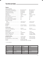
Engine ................................................................ 111
Fuel specification ............................................... 112
Drive-unit ............................................................ 112
© 2007 AB VOLVO PENTA
All rights to changes or modifications reserved.
Printed on environmentally friendly paper.
(Cover: Department of transport (shipping), license 9809095)
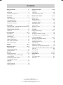
Contents

Safety Information
Read this chapter carefully. It concerns your safety. This section describes how safety information is presented in
the operator’s manual and on the engine. It also gives a general account of basic safety precautions to be taken
when operating the boat and maintaining the engine.
Check that you have the correct operator’s manual before you read on. If this is not the case please con-
tact your Volvo Penta dealer.
If operations are performed incorrectly it could result in personal injury, or damage to property
or the engine. Read the operator’s manual carefully before operating or servicing the engine. If
anything is unclear please contact your Volvo Penta dealer for assistance.
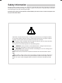
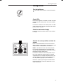
This symbol is used in the book and on the engine to make you aware of safety information.
Always read these safety precautions very carefully.
In the operator’s manual warning texts have the following priority:
WARNING! If these instructions are not followed there is a danger of personal injury,
extensive damage to the product or serious mechanical malfunction.
IMPORTANT! Used to draw your attention to something that can cause damage, prod-
uct malfunction or damage to property.
NOTE! Used to draw your attention to important information that will facilitate work or opera-
tions.
This symbol is used in certain cases on our products and refers to important information in
the operator’s manual. Ensure that warning and information symbols on the engine and trans-
mission are always visible and legible. Replace symbols that have been damaged or painted
over.
3

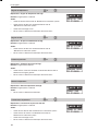
Safety precautions to be taken when operating the boat
Your new boat
Read operator’s manuals and other information
supplied with your new boat. Learn to operate the
engine, controls and other equipment safely and cor-
rectly.
If this is your first boat, or is a boat type with which
you are not familiar, we recommend that you prac-
tice controlling the boat in peace and quiet. Learn
how the boat behaves at different speeds, weather
conditions and loads before casting off for your “real”
maiden voyage.
Remember that the person driving a boat is legally
required to know and follow the current rules regard-
ing traffic and safety at sea. Make sure you know the
rules that apply to you and the waters you are sailing
in by contacting the relevant authorities or organiza-
tion.
A good piece of advice is to take a course in sea-
manship. We recommend that you contact your local
boating organization to find a suitable course.
Accidents
Statistics show that poor maintenance of boats and
engines and a lack of safety equipment are often the
cause of accidents at sea.
Ensure that your boat is maintained in accordance
with the relevant Instruction Manual and that the nec-
essary safety equipment is on-board and is service-
able.
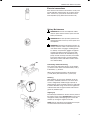
Daily checklist
Make a habit of checking the engine and engine
compartment visually before operating the boat (be-
fore the engine is started) and after operating the
boat (after the engine has been stopped). This will
help you to quickly detect fuel, coolant or oil leaks
and spot anything else unusual that has or is about to
happen.
Maneuvering
Avoid violent and unexpected changes in course and
gear engagement. This could cause someone on the
boat to lose their balance and fall over or overboard.
A rotating propeller can cause serious injury. Check
that nobody is in the water before engaging ahead or
astern. Never drive near bathers or in areas where
people could be in the water.
Refueling
When refueling there is always a danger of fire and
explosion. Smoking is forbidden and the engine must
be switched off.
Never overfill the tank. Close the fuel tank filler cap
properly.
Only use the fuel recommended in the operator’s
manual. The wrong grade of fuel can cause operat-
ing problems or cause the engine to stop. On a diesel
engine poor quality fuel can cause the control rod to
seize and the engine to overrev with a resultant risk
of damage to the engine and personal injury.
Do not start the engine
Do not start or run the engine with a suspected fuel
or LPG leak in the boat, nor when you are close to or
in a discharge of explosive media, etc. There is risk
for fire and/or explosion in explosive surroundings.
Safety breaker
We recommend that you install and use a safety
breaker (accessory), especially if you boat can travel
at high speeds. The safety breaker stops the engine if
the driver falls down and loses control over the boat.
Safety Information
4

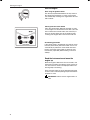
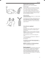
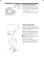
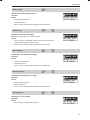
Carbon monoxide poisoning
When a boat is moving forward, it will cause a certain
vacuum to form behind the boat. In unfortunate cir-
cumstances, the suction from this vacuum can be so
great that the exhaust gases from the boat are drawn
into the cockpit or cabin and cause carbon monoxide
poisoning.
This problem is most prevalent on high, wide boats
with abrupt stern. In certain conditions, however, this
suction can be a problem on other boats, e.g. when
running with the cover up. Other factors that can in-
crease the effect of the suction are wind conditions,
load distribution, swells, trim, open hatches and port-
holes, etc.
Most modern boats, however, are designed in such
a way that this problem is very rare. If suction should
arise anyway, do not open hatches or portholes at
the fore of the boat. Surprisingly, this will otherwise
increase the suction. Try changing speed, trim or load
distribution instead. Try taking down/opening or in any
other way changing the setup of the cover as well.
Get in touch with your boat dealer for help in obtain-
ing the best solution for your boat.
Checklist
● Safety equipment Life jackets for all passengers, communication equipment, emergency rockets,
approved fire extinguisher, first-aid equipment, life belt, anchor, paddle, torch etc.
● Replacement parts and tools: impeller, fuel filters, fuses, tape, hose clamps, engine oil, propeller
and tools for any repairs that might have to be carried out.
● Get out your charts and go over the planned route. Calculate distance and fuel consumption.
Listen to the weather reports
● Make sure that relations or contact persons are informed when planning a longer voyage. Re-
member to inform them if your plans have changed or been delayed.
● Tell your passengers and crew where the safety equipment is stored and how to operate it.
Make sure you are not the only person on board who knows how to start the boat and operate it
safely.
This list can be added to because safety equipment and other requirements vary depending on the
type of boat and how it is used. We recommend that you contact your local boating organization for
more detailed information on safety afloat.
Safety Information
5

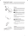
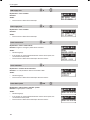
Safety precautions for maintenance and service operations
Preparations
Knowledge
The operator’s manual contains instructions on how
to carry out general maintenance and service opera-
tions safely and correctly. Read the instructions care-
fully before starting work.
Service literature covering more complicated opera-
tions is available from your Volvo Penta dealer.
Never carry out any work on the engine if you are
unsure of how it should be done, contact your Volvo
Penta dealer who will be glad to offer assistance.
Stop the engine
Stop the engine before opening or removing engine
hatches. Unless otherwise specified all maintenance
and service must be carried out with the engine
stopped.
To prevent accidental start of the boat engine remove
the ignition key, turn off the power supply to the en-
gine at the main switches and lock them in the OFF
position before starting work. Put up a warning sign
in the control position that work on the engine is be-
ing carried out.
Approaching or working on an engine that is run-
ning is a safety risk. Loose clothing, hair, fingers or
a dropped tool can be caught in the rotating parts of
the engine and cause serious personal injury. Volvo
Penta recommend that all servicing with the engine
running be undertaken by an authorized Volvo Penta
workshop.
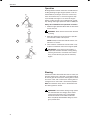
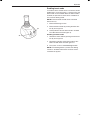
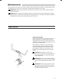
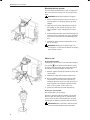
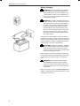
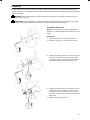
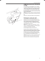
Lifting the engine
When lifting the engine use the lifting eyes installed
on the engine. Always check that lifting equipment is
in good condition and has sufficient load capacity to
lift the engine (engine weight r and any extra equip-
ment installed). For safety’s sake lift the engine us-
ing an adjustable lifting beam. All chains and cables
should run parallel to each other and as perpendicu-
lar as possible in relation to the top of the engine.
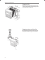
Bear in mind that extra equipment installed on the
engine may alter its center of gravity. Special lifting
equipment may then be required in order to maintain
the correct balance and make the engine safe to han-
dle. Never carry out work on an engine suspended on
a hoist.
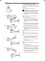
Before starting the engine
Reinstall all protective parts removed during service
operations before starting the engine. Check that no
tools or other items have been left on the engine.
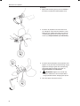
Never start a turbocharged engine without installing
the air cleaner (ACL). The rotating compressor in the
Turbocharger unit can cause serious personal injury.
Foreign objects can also be sucked in and cause me-
chanical damage to the unit.
Fire and explosion
Fuel and lubrication oil
All fuel, most lubricants and many chemicals are
inflammable. Read and follow the instructions on the
packaging.
When carrying out work on the fuel system make
sure the engine is cold. A fuel spill onto a hot surface
or electrical components can cause a fire.
Store fuel soaked rags and other flammable material
so that there is no danger of them catching fire. Fuel-
soaked rags can self-ignite under certain conditions.
Do not smoke when filling fuel, oil or in proximity of a
filling station or in the engine room.
Non-original components
Components used in the fuel and ignition system
(gasoline engines) and electrical systems on Volvo
Penta products are designed and constructed to
minimize the risk of fire and explosion.
Using non-original Volvo Penta parts can result in fire
or explosion on board.
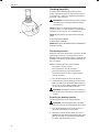
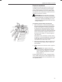
Batteries
The batteries contain and give off oxyhydrogen gas,
especially during charging. This gas is easily ignited
and highly volatile.
Do not under any circumstances smoke or use naked
flame or allow sparks in the vicinity of the batteries or
battery compartment.
Incorrectly connection a battery terminal cable or
jump-start cable can cause a spark which in its turn
can be sufficient to cause an explosion.
Start spray
Never use start spray or similar agents to start an en-
gine equipped with air pre-heating (glow plugs/starter
element). This may cause an explosion in the inlet
manifold. Danger of personal injury.
Safety Information
6

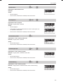
Hot surfaces and fluids
There is always a risk of burns when working with
a hot engine. Beware of hot surfaces. For example:
the exhaust pipe, Turbo unit, oil pan, charge air pipe,
starter element, hot coolant and hot oil in oil lines and
hoses.
Carbon monoxide poisoning
Only start the engine in a well-ventilated area. If op-
erating the engine in an enclosed space, ensure that
there is proper ventilation in order to remove exhaust
gases and crankcase ventilation emissions from the
working area.
Chemicals
Most chemicals such as anti-freeze, rustproofing
agent, inhibiting oil, degreasing agent etc. are haz-
ardous to health. Read and follow the instructions on
the packaging.
Some chemicals such as inhibiting oil are inflam-
mable and dangerous if breathed in as well. Ensure
good ventilation and use a protective mask when
spraying. Read and follow the instructions on the
packaging.
Store chemicals and other hazardous materials out
of the reach of children. To protect the environment
please dispose of used or leftover chemicals at a
properly designated disposal site for destruction.
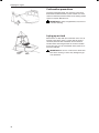
Cooling system
There is a risk of flooding when working on the sea-
water system. Turn off the engine and close the sea
cock (where installed) before starting work on the
system.
Avoid opening the coolant filler cap when the engine
is hot. Steam or hot coolant can spray out and cause
burns.
If work must be carried out with the engine at operat-
ing temperature and the coolant filler cap or a cock
open or a coolant hose disconnected, open the cool-
ant filler cap carefully and slowly to release pressure
before removing the cap completely. Note that the
coolant may still be hot and can cause burns.
Lubrication system
Hot oil can cause burns. Avoid skin contact with hot
oil. Ensure that the lubrication system is not under
pressure before commencing work on it. Never start
or operate the engine with the oil filler cap removed,
oil can spray out.
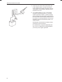
Fuel system
Always use protective gloves when tracing leaks.
Liquids ejected under pressure can penetrate body
tissue and cause serious injury. There is a danger of
blood poisoning.
Always cover the generator if it is located under the
fuel filter. The generator can be damaged by spilled
fuel.
Steering system
The boat has a advanced steering system. DO NOT
change connectors, wiring or splice of the compo-
nents.
Service must be done by approved workshops which
have certifed personnel with qualified professional
training.
Electrical system
Cutting off power
Always stop the engine and break the current using
the main switches before working on the electrical
system. Isolate shore current to the engine block
heater, battery charger, or accessories mounted on
the engine.
Batteries
The batteries contain an extremely corrosive elec-
trolyte. Protect your skin and clothes when charging
or handling batteries. Always use protective goggles
and gloves.
If battery electrolyte comes into contact with unpro-
tected skin wash off immediately using plenty of wa-
ter and soap. If battery acid comes into contact with
the eyes, flush immediately with plenty of water and
obtain medical assistance without delay.
Safety Information
7

Introduction
This operator’s manual has been compiled to help you get the most from your Volvo Penta engine. It contains
all the information you need in order to operate and maintain your engine safely and correctly. Please read the
operator’s manual carefully and learn how to operate the engine, controls and other equipment safely.
Always have the operator’s manual available. Keep it in a safe place and do not forget to give it to the new owner
if you sell your boat.
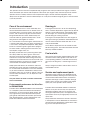
Care of the environment
We would all like to live in a clean and healthy envi-
ronment. Somewhere where we can breathe clean air,
see healthy trees, have clean water in our lakes and
oceans, and are able to enjoy the sunshine without
being worried about our health. Unfortunately, this
cannot be taken for granted nowadays but is some-
thing we must work together to achieve.
As a manufacturer of marine engines, Volvo Penta has
a special responsibility, why care of the environment is
a core value in our product development. Today, Volvo
Penta has a broad range of engines where progress
has been made in reducing exhaust emissions, fuel
consumption, engine noise, etc.
We hope you will take care in preserving these quali-
ties. Always follow any advice given in the instruc-
tion manual concerning fuel grades, operation and
maintenance and you will avoid causing unecessary
interference to the environment. Get in touch with your
Volvo Penta dealer if you notice any changes such as
increased fuel consumption exhaust smoke.
Adapt speed and distance to avoid wash and noise
disturbing or injuring animal life, moored boats, jetties,
etc. Leave islands and harbours in the same condition
as you want to find them. Remember to always leave
hazardous waste such as waste oil, coolant, paint and
wash residue, flat batteries, etc., for disposal at a de-
struction plant.
Our joint efforts will make a valuable contribution
to our environment.
Environmental performance for Volvo Pen-
ta IPS500/IPS400
The Volvo Penta IPS500 /IPS400 has been developed
as a complete system with excellent environmental
performance as one of the main design targets. The
very high efficiency of the Volvo Penta IPS system
gives greatly reduced overall emissions per nautical
mile. Sound emissions are also extremely low com-
pared with traditional inboard installations.
Running-in
The engine must be run in for its first 10 operating
hours as follows: Operate the engine normally. Do not
operate it at full load except for short periods. Never
run the engine at a constant engine speed for long
periods during the running-in period.
The engine can be expected to use more engine oil
during the running-in period than would otherwise be
normal. Check the oil level more often than is nor-
mally recommended.
A First Service Inspection must be carried out after
20–50 running hours. For further information: See the
Warranty and Service Book.
Fuel and oils
Only use the fuel and oils recommended in the chap-
ter Technical Data. Other grades of fuel and oil can
cause operating problems, increased fuel consump-
tion and, in the long-term, a shorter engine service
life.
Always change oil, oil filters and fuel filters at the re-
commended intervals.
Service and replacement parts
Volvo Penta marine engines are designed for high
operational reliability and long service life. They are
constructed to withstand the marine environment
while also affecting it as little as possible. Through
regular service and the use of Volvo Penta original
spare parts, these qualities will be retained.
The Volvo Penta worldwide network of authorized
dealers are at your service. They are specialists in
Volvo Penta products and have accessories and
the original replacement parts, test equipment and
special tools necessary for high quality service and
repair work.
Always follow the maintenance intervals contained
in the operator’s manual. Remember to state the en-
gine/transmission identification number when order-
ing service and replacement parts.
8

Warranty
Your new Volvo Penta marine engine is covered by a limited warranty according to the conditions and
instructions contained in the Warranty and Service book.
Note that AB Volvo Penta’s liability is limited to that contained in the Warranty and Service Book. Read
this book as soon as you take delivery of the engine. It contains important information about warranty
cards, service and maintenance which you, the owner, must be aware of, check and carry out. Liability
covered in the warranty may otherwise be refused by AB Volvo Penta.
Contact your Volvo Penta dealer if you have not received a Warranty and Service Book and a
customer copy of the warranty card.
Certified engines
It is important to be aware of the following information
if you own or run an engine that is exhaust emission
certified:
Certification means that an engine type is inspected
and approved by the authorities. The engine manu-
facturer guarantees that all engines manufactured of
that type correspond to the certified engine.
This places special requirements for maintenance
and service as follows:
● The maintenance and service intervals recom-
mended by Volvo Penta must be observed.
● Only by Volvo Penta approved replacement parts
may be used.
● The service of injection pumps and injectors or
pump settings must always be carried out by an
authorized Volvo Penta workshop.
● The engine must not be modified in any way ex-
cept with accessories and service kits approved
by Volvo Penta.
● No modifications to the exhaust pipes and air
supply ducts for the engine may be undertaken.
● Seals may only be broken by authorized person-
nel.
Otherwise the general instructions contained in the
Operator's Manual concerning operation, service and
maintenance must be followed.
IMPORTANT! Late or inadequate maintenance/
service or the use of spare parts other than by
Volvo Penta approved spare parts will invalidate
AB Volvo Penta’s responsibility for the engine
specification being in accordance with the cer-
tificated variant.
Volvo Penta accepts no responsibility or liabil-
ity for any damage or costs arising due to the
above.
Introduction
9

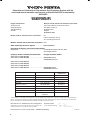
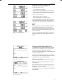
Body for sound and exhaust emission assessment
International Marine Certification Institute
Rue Abbé Cuypres 3
B-1040 Bruxells
Belgium
ID Number: 0609
Declaration of Conformity for Recreational Craft Propulsion Engines with the
sound and exhaust emission requirements of Directive 94/25/EC as amended by
2003/44/EC
Engine manufacturer
AB Volvo Penta
Gropegårdsgatan
405 08 Göteborg
Sweden
VOLVO PENTA IPS
Essential requirements
Annex I.B – Exhaust Emissions
Engine identification
Exhaust emission requirements
Durability
Operator’s manual
Annex I.C – Noise Emissions
Sound emission levels
Operator’s manual
EMC Directive
Standards Used
Volvo Penta std
EN ISO 8178-1:1996
Volvo Penta std
ISO 10240:2004
EN ISO 14509:2000/prA1:2004
ISO 10240:2004
EN 61000-3-2, EN 61000-3-3,
CISPR 25
Other normative do-
cument used
Annex I.B.1
Annex I.B.2
Annex I.B.3
Annex I.B.4
Annex I.C.1
Annex I.C.2
Name and function: Sam Behrmann, Laws and Regulations
(identification of the person empowered to sign on behalf of the
engine manufacturer or his authorised representative)
Signature and title:
(or an equivalent marking)
Date and place of issue: (yr/month/day) 2007/04/26 Göteborg
This declaration of conformity is issued under the sole responsibility of the manufacturer. I declare on behalf of the engine manufacturer
that the engine(s) mentioned above complie(s) with all applicable essential requirements in the way specified and is in conformity with
the type for which above mentioned EC type examination certificate(s) has been issued.
Module used for sound emission assessment .....Aa
Internal production control
Test according to Annex VI
Modules used for exhaust emission assessment B+C
Other Community Directives applied .....................EMC 89/336/EEC
Description of engine(s) and essential requirements
Engine type ...................................................................4 stroke diesel engine with stern drive
................................................................................with integral exhaust
Engine(s) models covered by this declaration EC Type certificate number
Volvo Penta IPS 350 (D4-260)
Volvo Penta IPS 400 (D4-300) ......................................SDVOLV005 (noise)
EXVOLV001 (exhaust)
Volvo Penta IPS 400 (D6-310)
Volvo Penta IPS 450 (D6-330)
Volvo Penta IPS 500 (D6-370)
Volvo Penta IPS 600 (D6-435) ......................................SDVOLV004 (noise)
EXVOLV001 (exhaust)
PL-101/07
10

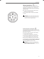
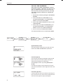
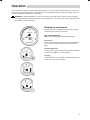
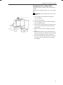
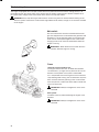
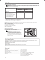
Identification numbers
Always provide the engine and transmission identification numbers when ordering service or replacement com-
ponents.
The identification numbers are on an information decal located on the front edge of the engine. Note the infor-
mation below. Make a copy of the page. Store the information so that it is available in event of the boat being
stolen.
Engine
Product designation (1*)
Serial number (2*)
Product number (3*)
Drive-unit
Product designation (4*)
Gear ratio (5*)
Serial number (6*)
Product number (7*)
* The numbers refer to the position of the identification numbers on
the information decal
Location of information decal and identification plates:
Introduction
Engine plate
Warranty decal, IMO decal, Exhaust Emission cetificate,
and EPA decal
Drive-unit
plate
Warranty decal (Engine/Drive-unit)
Engine plate
Drive-unit plate
11

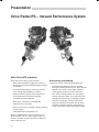
Presentation
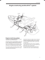
Volvo Penta IPS – Inboard Performance System
Volvo Penta IPS overvieiw
Volvo Penta IPS is setting a new standard:
– Much improved efficiency, higher top speed, re-
duced fuel consumption/extended range and great
acceleration
– Low-speed maneuvering is easier than ever be-
fore, and high speed handling is a dream
– Onboard comfort is greatly enhanced thanks to
much lower levels of sound and vibrations
– Installation is greatly simplified
– More space available for accommodation
– Improved safety and quality
– Ease of service and a complete system supported
by one supplier
– Improved overall environmental care
All this is combined with the usual benefits of a tra-
ditional inboard such as a robust, high strength con-
struction, excellent corrosion resistance and the pro-
pellers under the hull.
Maneuvering and handling
The reasons for the amazing maneuverability are:
– The Volvo Penta IPS drive-units are steerable,
turning and pointing the entire thrust in the desired
direction. This results in much higher efficiency
and far greater response to driver commands.
– Two counter-rotating propellers on each propul
-
sion unit means that there are no lateral forces to
consider and that tracking is completely straight.
– Electronic controls give a distinct and precise
feeling, and shifting is immediate. Thanks to the
progressive electronic steering, the wheel spins
easier at low speed, further reducing driver effort.
12

Comfort
Volvo Penta IPS new technology leads to major im-
provements for all comfort enhancing factors.
– The propulsion forces and vibrations are absorbed
by the combined rubber suspension and sealing.
– A U-joint in the drive shaft makes it possible to
have the engine soft suspended, which efficiently
reduces engine vibrations.
– The propellers are working in undisturbed water
with no cavitation, and have good clearance from
the hull.
– There is an increased number of propeller blades
to distribute the forces. This means that the pulses
created by the propellers have very little effect on
the hull.
– Exhaust fumes are truly minimized. First of all, the
new engine has very low exhaust emissions, and
secondly, the exhausts are emitted through the
propulsion unit into the prop wash and carried well
behind the boat.
Installation
The Volvo Penta IPS system can be installed in vari-
ous ways, either as a compact system or with an ex-
tended jackshaft, giving opportunities for different boat
designs.
The system is always used in twin engine installation
configuration.
Safety and quality
Heavy duty material throughout means excellent cor-
rosion resistance. Everything in contact with seawater
is either made from a specially formulated nickel-alu-
minum-bronze alloy or stainless steel. Propulsion unit,
bearings, couplings, etc. are all robustly dimensioned
to cope with the unexpected and ensure a really long
and trouble-free service life.
EVC handles all communication and monitoring in-
cluding shift, throttle and steering. Several safety func-
tions in the system minimize the risk of damage to
engine or propulsion unit.
The Volvo Penta IPS system is designed with full re-
dundancy, i.e. even if you have a total breakdown in
one driveline, the remaining one will bring you home
safely.
Environmental care
The Volvo Penta IPS has been developed as a com-
plete system with excellent environmental perfor-
mance as one of the main design targets. The very
high efficiency of the Volvo Penta IPS system gives
greatly reduced overall emissions.
Volvo Penta’s new D6 in-line engines have been de-
veloped from the latest design in modern diesel tech-
nology. The engines have common rail fuel injection
system, double overhead camshafts, 4 valves per cyl-
inder, turbocharger, compressor (Volvo Penta IPS 350,
IPS 500 and IPS 600), and aftercooler. The interaction
of these, the large swept volume, and the EVC system
results in exceptional diesel performance combined
with low emissions.
The D4/D6 engines have emission levels that meet
the forthcoming, stringent US and EU regulations due
in 2006.
13
Presentation

Engine technical description
Volvo Penta’s D6 is developed from the latest design in modern diesel technology. The engine has common rail
fuel injection system, double overhead camshafts, 4 valves per cylinder, turbocharger, compressor, and after-
cooler. The interaction of these, the large swept volume, and the EVC system results in exceptional diesel per-
formance combined with low emissions.
Engine block and head
— Cylinder block and cylinder head made of cast-iron
— Ladder frame fitted to engine block
— Double overhead camshafts
— Oil-cooled pistons with two compression rings and
one oil scraper ring
— Integrated cylinder liners
— Replaceable valve seats
— Seven-bearing crankshaft
— Rear-end transmission
Engine mounting
— Flexible engine mounting
Lubrication system
— Easily replaceable separate full-flow and by-pass
oil filter
— Seawater-cooled tubular oil cooler
Fuel system
— Common rail fuel injection system
— Control unit for processing the injection
— Fine filter with water separator
Air inlet and exhaust system
— Belt-driven compressor with silencer of absorption
type on both inlet and output port
— Air filter with replaceable insert
— Crankcase gases vented into the air inlet
— Exhaust elbow or exhaust riser
— Freshwater-cooled turbocharger
Cooling system
— Thermostatically regulated freshwater cooling
— Tubular heat exchanger with separate large vol
-
ume expansion tank
— Coolant system prepared for hot water outlet
— Seawater strainer and easily accessible impeller
pump
Electrical system
— 12V/24V two-pole electrical system
— 115A/80A marine alternator with Zener-diodes to
protect the system from peak voltage, and inte-
grated charging regulator with battery sensor ca-
ble for maximum use of alternator
— Fuses with automatic reset
— Aux. stop device
Instruments/control
— Complete instrumentation including key switch and
interlocked alarm
— EVC monitoring panels for single or twin installa-
tions
— Electronic remote control for throttle and shift
— Plug-in connections
Accessories
— An extensive range of accessories are available.
For detailed information, please see Accessory
catalogs.
14
Presentation

Engine monitoring system
The engines are equipped with common rail system
and electronically controlled injectors.
The injectors contain an electro-magnetic valve which
sets the amount of fuel injected and the correct tim-
ing. The monitoring system measures the charge air
pressure and temperature, and calculates the avail-
able air mass. This determines the maximum amount
of fuel that can be injected (smoke limiter function).
The system also limits the maximum torque available
at the engine speed registered to protect the engine
and transmission from overload.
To protect the engine at too high coolant or charge air
temperatures and boost pressure as well as oil pres-
sure, the monitoring system reduces the amount of
fuel (reduced engine output) until the current values
are normalized.
The engine monitoring system also has a diagnostic
system, which helps users and service technicians to
determine the cause of malfunctions.
Users get information about faults by pop-ups that
are shown on the EVC system tachometer display.
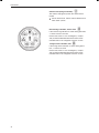
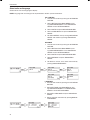
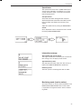
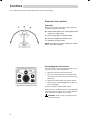
Engine monitoring and the EVC
EC
system
Helm station
Control Unit
(SHCU)
Power train
Control Unit
(PCU)
Engine
Control Unit
(ECU)
Helm station
Control Unit
(HCU)
CAN bus
Servo Unit
Steering
(SUS)
Steering unit
15
Presentation

The EVC
EC
system
The Electronic Vessel Control (EVC) system is a so
called distributed system. The principle of a distrib-
uted system is to have "small" electronic units, called
nodes, located at suitable places in the boat.
The EVC nodes are the Powertrain Control Unit (PCU)
and the Steering Helm station Control Unit (SHCU).
Nodes are located close to the components they con-
trol. A helm node is located close to the helm. A pow-
ertrain node is mounted in the engine room.
Each node controls a number of adjacent compo-
nents, such as sensors, controls, instruments and
actuators.
Each PCU and HCU is programmed for a specific
engine. There is a sticker with serial no. and chassis
no. on each PCU and HCU. The chassi no. must cor-
respond with the sticker on the engine.
A data bus, a CAN bus, connects the nodes to each
other. Together they form a network and exchange
information and take advantage of each others’ ser-
vices. The principle of forming a network of nodes to
which all components are connected reduces wiring
radically. A CAN bus can be very long, but in the EVC
system the bus length shall not exceed 50 meters.
CAN stands for Controller Area Network, an industry
standard for communication between nodes in distrib-
uted systems.
A distributed system supports a growing multiplicity
of system configurations and optional features. New
nodes can be connected to the network with minimal
wiring redesign. New effective functionality can be cre-
ated by letting the nodes interact and combine their
capabilities, creating a more useful and safe product.
Functionality
Steering system
The steering system is operated through the EVC
system and gives a smooth and exact steering. It also
provides possibilities, which are not possible with a
traditional steering system.
The helm steering unit sends an electrical signal via
the EVC system to the servo unit fitted on the drive-
unit.
The steering is progressive and the turn rate auto-
matically adjusted to suit the actual boat speed for
optimised comfort and boat handling.
For reliability the steering system is built with redun-
dancy on several levels.
Engine speed and gear shift
Speed and gear shift contol is handled electronically
with dual function electronic controls.
Multiple helm stations
Up to four helm stations can easily be installed (plug
in). The EVC system provides different options for sta-
tion transfers in neutral position or under way. Another
safety feature is a helm station "lock function" to avoid
unexepted station transfers.
Engine synchronization
Engine synchronization results in better comfort, good
fuel ecomomy and minimized wear due to less vibra-
tion and reduced noise level. The master (port) and
slave (starboard) systems must be able to communi-
cate to allow synchronization. For this reason a syn-
chronization cable must be installed at each helm.
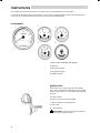
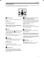
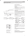
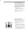
Instrumentation
The instruments use a serial communication bus. The
serial communication bus in combination with EVC
radically reduces wiring and simplifies installation.
Gauges are available with white or black dial face and
chromed or black bezel.
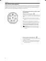
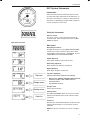
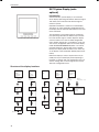
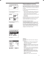
EVC system tachometer
The EVC system tachometer is mandatory for boats
with EVC, unless the optional EVC system display
is installed. The tachometer display shows operation
information, information massages and alarms. The
user selects what operation information to display with
the control panel. NOTE! Only one operation informa-
tion can be displayed at one and the same time.
The EVC system tachometer and control panel is also
used when calibrating EVC functions.
Extra optional equipment
EVC system display
The EVC system display is a complement or replace-
ment for EVC system tachometer and optional instru-
ments. The display shows operation information, infor-
mation massages and alarms. The user selects what
operation information to display with the buttons on
the display. The EVC system display can display more
than one operation information at one and the same
time. The display also has access to the same display
mode and calibration functions as for the EVC system
tachometer display.
16
Presentation

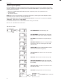
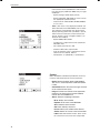
Fuel level
Fuel level can be displayed on the EVC system ta-
chometer if a (0-180 ohm or 240-30 ohm) fuel level
sender is installed in the fuel tank. The sender is con-
nected to the PCU–engine cable harness. If a fuel
level gauge is used it must be connected to the instru-
ment serial communication bus.
Fresh water level
Fresh water level can be displayed on the EVC sys-
tem tachometer if a (0-180 ohm) fuel level sender is
installed in the water tank. The sender is connected to
the PCU–engine cable harness. If a fresh water level
gauge is used it must be connected to the instrument
serial communication bus.
Rudder indicator
A rudder indicator sender is included in all drive-units.
The rudder angle can be displayed on the EVC sys-
tem tachometer. If a rudder instrument is used it must
be connected to the instrument serial communication
bus.
Multi sensor (Boat speed, depth and water temp)
Boart speed, depth and water temperature canbe dis-
played on the EVC system tachometer if a multi sen-
sor is installed on the boat. The sensor is connected to
the multilink cable. If instruments (speed, depth, water
temp.) are used they must be connected to the instru-
ment serial communication bus.
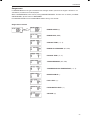
Boat speed
Boat speed can be shown on the EVC system ta-
chometer, if a multisensor or NMEA 0183/NMEA 2000
compatible component (plotter, GPS, paddle wheel
etc) is installed. If a speedometer is used it must be
connected to the instrument serial communication bus.
.
Trip computer
EVC supports trip computer functions if following are
installed.
- multisensor or NMEA 0183/NMEA 2000 compatible
component (plotter, GPS, paddle wheel etc)
- fuel level sender
- software for trip computer (order and download from
VODIA website).
Trip computer information can be displayed on the
EVC system tachometer or/and on the optional EVC
system display.
17
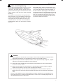
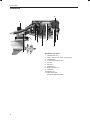
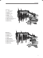
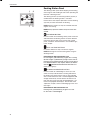
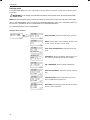
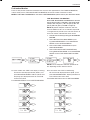
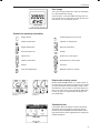
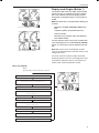
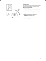
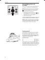
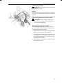
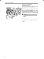
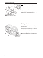
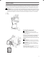
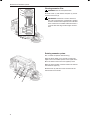
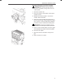
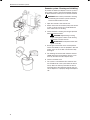
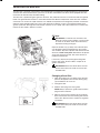
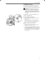
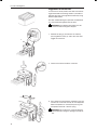
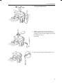
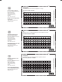
Presentation

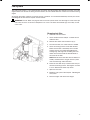
(D4)/D6-IPS, starboard
1. Oil filter, drive-unit
2. Water shut off valve, drive-unit (only D6)
3. Turbocharger
4. Crankcase ventilation filter
5. Air filter
6. Aux stop
7. Compressor
8. Engine control unit
9. Generator
10. Oil filler cap
11. Volvo Penta IPS,
Servo Unit Steering (SUS)
Orientation
1
2
3
4
5
6
7
9
10
8
11
18
Presentation
La pagina si sta caricando...
La pagina si sta caricando...
La pagina si sta caricando...
La pagina si sta caricando...
La pagina si sta caricando...
La pagina si sta caricando...
La pagina si sta caricando...
La pagina si sta caricando...
La pagina si sta caricando...
La pagina si sta caricando...
La pagina si sta caricando...
La pagina si sta caricando...
La pagina si sta caricando...
La pagina si sta caricando...
La pagina si sta caricando...
La pagina si sta caricando...
La pagina si sta caricando...
La pagina si sta caricando...
La pagina si sta caricando...
La pagina si sta caricando...
La pagina si sta caricando...
La pagina si sta caricando...
La pagina si sta caricando...
La pagina si sta caricando...
La pagina si sta caricando...
La pagina si sta caricando...
La pagina si sta caricando...
La pagina si sta caricando...
La pagina si sta caricando...
La pagina si sta caricando...
La pagina si sta caricando...
La pagina si sta caricando...
La pagina si sta caricando...
La pagina si sta caricando...
La pagina si sta caricando...
La pagina si sta caricando...
La pagina si sta caricando...
La pagina si sta caricando...
La pagina si sta caricando...
La pagina si sta caricando...
La pagina si sta caricando...
La pagina si sta caricando...
La pagina si sta caricando...
La pagina si sta caricando...
La pagina si sta caricando...
La pagina si sta caricando...
La pagina si sta caricando...
La pagina si sta caricando...
La pagina si sta caricando...
La pagina si sta caricando...
La pagina si sta caricando...
La pagina si sta caricando...
La pagina si sta caricando...
La pagina si sta caricando...
La pagina si sta caricando...
La pagina si sta caricando...
La pagina si sta caricando...
La pagina si sta caricando...
La pagina si sta caricando...
La pagina si sta caricando...
La pagina si sta caricando...
La pagina si sta caricando...
La pagina si sta caricando...
La pagina si sta caricando...
La pagina si sta caricando...
La pagina si sta caricando...
La pagina si sta caricando...
La pagina si sta caricando...
La pagina si sta caricando...
La pagina si sta caricando...
La pagina si sta caricando...
La pagina si sta caricando...
La pagina si sta caricando...
La pagina si sta caricando...
La pagina si sta caricando...
La pagina si sta caricando...
La pagina si sta caricando...
La pagina si sta caricando...
La pagina si sta caricando...
La pagina si sta caricando...
La pagina si sta caricando...
La pagina si sta caricando...
La pagina si sta caricando...
La pagina si sta caricando...
La pagina si sta caricando...
La pagina si sta caricando...
La pagina si sta caricando...
La pagina si sta caricando...
La pagina si sta caricando...
La pagina si sta caricando...
La pagina si sta caricando...
La pagina si sta caricando...
La pagina si sta caricando...
La pagina si sta caricando...
La pagina si sta caricando...
La pagina si sta caricando...
La pagina si sta caricando...
La pagina si sta caricando...
La pagina si sta caricando...
La pagina si sta caricando...
La pagina si sta caricando...
La pagina si sta caricando...
La pagina si sta caricando...
La pagina si sta caricando...
-
 1
1
-
 2
2
-
 3
3
-
 4
4
-
 5
5
-
 6
6
-
 7
7
-
 8
8
-
 9
9
-
 10
10
-
 11
11
-
 12
12
-
 13
13
-
 14
14
-
 15
15
-
 16
16
-
 17
17
-
 18
18
-
 19
19
-
 20
20
-
 21
21
-
 22
22
-
 23
23
-
 24
24
-
 25
25
-
 26
26
-
 27
27
-
 28
28
-
 29
29
-
 30
30
-
 31
31
-
 32
32
-
 33
33
-
 34
34
-
 35
35
-
 36
36
-
 37
37
-
 38
38
-
 39
39
-
 40
40
-
 41
41
-
 42
42
-
 43
43
-
 44
44
-
 45
45
-
 46
46
-
 47
47
-
 48
48
-
 49
49
-
 50
50
-
 51
51
-
 52
52
-
 53
53
-
 54
54
-
 55
55
-
 56
56
-
 57
57
-
 58
58
-
 59
59
-
 60
60
-
 61
61
-
 62
62
-
 63
63
-
 64
64
-
 65
65
-
 66
66
-
 67
67
-
 68
68
-
 69
69
-
 70
70
-
 71
71
-
 72
72
-
 73
73
-
 74
74
-
 75
75
-
 76
76
-
 77
77
-
 78
78
-
 79
79
-
 80
80
-
 81
81
-
 82
82
-
 83
83
-
 84
84
-
 85
85
-
 86
86
-
 87
87
-
 88
88
-
 89
89
-
 90
90
-
 91
91
-
 92
92
-
 93
93
-
 94
94
-
 95
95
-
 96
96
-
 97
97
-
 98
98
-
 99
99
-
 100
100
-
 101
101
-
 102
102
-
 103
103
-
 104
104
-
 105
105
-
 106
106
-
 107
107
-
 108
108
-
 109
109
-
 110
110
-
 111
111
-
 112
112
-
 113
113
-
 114
114
-
 115
115
-
 116
116
-
 117
117
-
 118
118
-
 119
119
-
 120
120
-
 121
121
-
 122
122
-
 123
123
-
 124
124


Volvo Penta IPS 600 Manuale utente
- Categoria
- Motore
- Tipo
- Manuale utente
in altre lingue
- English: Volvo Penta IPS 600 User manual
Documenti correlati
-
 Volvo Penta D4 Manuale utente
-
Volvo D2-55 Manuale utente
-
 Volvo Penta D12 Manuale utente
-
 Volvo Penta TAMD63L Manuale utente
-
 Volvo Penta AQAD30/DP Instruction book
-
 Volvo Penta Easy Connect Interface Installation Instructions Manual
-
 Volvo Penta D3 290/DP Installation Instructions Manual
-
Volvo Penta D2-40 Guida d'installazione
-
 Volvo Penta MDI Installation Instructions Manual
-


Altri documenti
-
Greenworks GW060 Manuale utente
-
-
-
Hikoki EC36DA Manuale utente
-
Regal 42 Fly-Grande Coupe Manuale del proprietario
-
Yanmar 6HYM-WET Istruzioni per l'uso
-
GCE PRESSURE WATCH Istruzioni per l'uso
-
Zanussi Z 70 VS Manuale del proprietario
-
Ingersoll-Rand R30 Product Maintenance Information
-
Garmin GHP Reactor™ Hydraulic Autopilot Guida d'installazione