
组装说明
CN
Instrukcje składanIa
PL
Montážní návod
CZ
KoKoamisohjeet
FI
Monteringsanvisningar
SE
Montage-instrucies
NL
Instruções de Instalação
PT
InstruccIones de InstalacIón
ES
InstruzIoInI per l‘InstallazIone
IT
InstallatIon InstructIons
EN
InstructIons pour l‘InstallatIon
FR
Original-MOntageanleitung
DE
RGRG

2

3

4

5

CN PL CZ FI SE NL PT ES IT EN FR DE
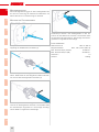
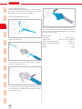
Montageanleitung
Diese Montageanleitung gilt für das Zusatzgetriebe RG.
Es dient zur Erhöhung der Drehzahl an Maschinen mit
DIN 10 Anschluss zur Übersetzung ins Schnelle.
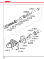
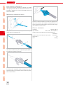
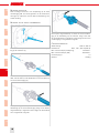
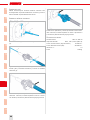
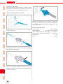
Montage des ZusatZgetriebes
Die Spindel an der Maschine blockieren (1). Die Wellen-
kupplung an die Maschine schrauben (2).
Schlüssel (1) in das Zusatzgetriebe einstecken und fest-
halten. Wellenseele an der Biegsamen Welle herauszie-
hen und an das Zusatzgetriebe schrauben (2).
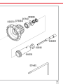
Arretierknopf drücken und Biegsame Welle in den An-
schluss am Zusatzgetriebe einsetzen. Sicherstellen dass
der Arretierknopf eingerastet ist. Demontage der Bieg-
samen Welle in umgekehrter Reihenfolge.
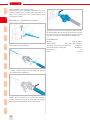
Arretierknopf drücken und Zusatzgetriebe in den An-
schluss an der Maschine einsetzen. Sicherstellen dass
der Arretierknopf eingerastet ist. Demontage des Zusatz-
getriebes in umgekehrter Reihenfolge.
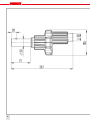
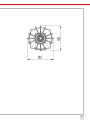
leistungsdaten
Wellenanschluss DIN 10 / DIN 10
Biegsame Wellen NA 4 , NA 7, NA 10 (DIN 10)
Max. Drehzahl Input (Antrieb) 12‘000min-1
Max. Drehzahl Output (RG) 36‘000min-1
Getriebe i= 1:3
Gewicht 1.300kg
DE
6

CN PL CZ FI SE NL PT ES IT EN FR DEDE
7

CN PL CZ FI SE NL PT ES IT EN FR
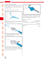
instructions pour l‘installation
Ces instructions pour l’installation s’appliquent au trans-
mission auxiliaire RG. Il est utilisé pour augmenter la vi-
tesse sur les machines avec une connexion DIN 10 pour
une traduction rapide.
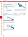
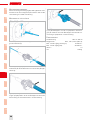
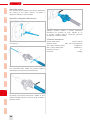
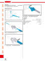
Montage de la transMission auxiliarie
Bloque la broche de la machine (1). Visser l’accouple-
ment d’arbre sur la machine (2).
Insérez la clé (1) au transmission auxiliarie et maintenez-
la. Tirez le noyau de l’arbre sur l’arbre flexible et vissez-le
sur la transmission auxiliaire (2).
Appuyez sur le bouton de verrouillage et insérez l’arbre
flexible dans le raccord de la transmission auxiliaire.
Assurez-vous que le bouton de verrouillage est engagé.
Démontage de l’arbre flexible dans l’ordre inverse.
Appuyez sur le bouton de verrouillage et insérez la trans-
mission auxiliaire dans le raccord de la machine. Assurez-
vous que le bouton de verrouillage est engagé. Démon-
tage de la transmission auxiliaire dans l’ordre inverse.
perforMances
Raccord DIN 10 / DIN 10
Arbres flexible NA 4 , NA 7, NA 10 (DIN 10)
Vitesse de rotation Input (entraînement) 12‘000min-1
Vitesse de rotation Output (RG) 36‘000min-1
Transmission i= 1:3
Poids 1.300kg
DE
FR
8

CN PL CZ FI SE NL PT ES IT EN FR DEFR
9

CN PL CZ FI SE NL PT ES IT EN
installation instructions
These installation instructions apply to the RG auxiliary
gear unit. It is used to increase the speed on machines
with a DIN 10 connection for rapid translation.
fitting of auxiliary gear unit
Block the spindel on the machine (1). Screw the shaft cou-
pling to the machine (2).
Insert the key (1) in the auxiliary gear unit and hold it there.
Pull out the shaft core on the flexible shaft and screw it
onto the auxiliary gear unit. (2)
Press the locking button and insert the flexible shaft into
the connection on the auxiliary gear unit. Make sure that
the locking button is engaged. Disassembly of the flexible
shaft in reverse order.
Press the locking button and insert the auxiliary gear unit
into the connection on the machine. Make sure that the
locking button is engaged. Disassembly of the auxiliary
gear unit in reverse order.
rating data
Connection DIN 10 / DIN 10
Flexible shafts NA 4 , NA 7, NA 10 (DIN 10)
Maximum speed Input (drive) 12‘000min-1
Maximum speed Output (RG) 36‘000min-1
Gear i= 1:3
Weight 1.300kg
FR DE
EN
10

CN PL CZ FI SE NL PT ES IT EN FR DEEN
11

CN PL CZ FI SE NL PT ES IT
instruZioni per l‘installaZione
Le presenti istruzioni per l‘installazione si applicano al azi-
onamento ausiliario RG. Viene utilizzato per aumentare la
velocità sulle macchine con una connessione DIN 10 per
una traduzione rapida.
Montaggio del aZionaMento ausiliario
Bloccare il mandrino sulla macchina (1). Avvitare il giunto
dell‘albero alla macchina (2).
Inserire la chiave (1) nel azionamento ausiliario e tenerla lì.
Estrarre il nucleo dell‘albero sull‘albero flessibile e avvitar-
lo sull‘azionamento ausiliario (2).
Premere il pulsante di bloccaggio e inserire l‘albero fles-
sibile nella connessione sull‘azionamento ausiliario. Assi-
curarsi che il pulsante di blocco sia inserito. Smontaggio
dell‘albero flessibile in ordine inverso.
Premere il pulsante di blocco e inserire il azionamen-
to ausiliario nella connessione sulla macchina. Assicu-
rarsi che il pulsante di blocco sia inserito. Smontaggio
dell‘azionamento ausiliario in ordine inverso.
dati sulle prestaZioni
Raccordo DIN 10 / DIN 10
Alberi flessibile NA 4 , NA 7, NA 10 (DIN 10)
Velocità massima di rotazione Input (azionamento)
12‘000min-1
Velocità massima di rotazione Output (RG) 36‘000min-1
Azionamento i= 1:3
Peso 1.300kg
EN FR DE
IT
12

CN PL CZ FI SE NL PT ES IT EN FR DEIT
13

CN PL CZ FI SE NL PT ES
instrucciones de instalación
Estas instrucciones de instalación se aplican a la unidad
de engranaje auxiliar RG. Se utiliza para aumentar la ve-
locidad en máquinas con una conexión DIN 10 para una
traducción rápida.
Montagje del engranaje auxiliar
Bloquee el husillo en la máquina (1). Atornille el acopla-
miento del eje a la máquina (2).
Inserte la llave (1) en el engranaje auxiliar y manténgala
allí. Tire del núcleo del eje en el eje flexible y atorníllelo en
la unidad de engranaje auxiliar (2).
Presione el botón de bloqueo e inserte el eje flexible en
la conexión del engranaje auxiliar. Asegúrese de que el
botón de bloqueo esté activado. Desmontaje del eje flexi-
ble en orden inverso.
Presione el botón de bloqueo e inserte el engranaje au-
xiliar en la conexión de la máquina. Asegúrese de que el
botón de bloqueo esté activado. Desmontaje del engra-
naje auxiliar en orden inverso.
datos de rendiMiento
Conexión DIN 10 / DIN 10
Ejes flexibles NA 4 , NA 7, NA 10 (DIN 10)
No de revoluciones máximo Input (accionamiento)
12‘000min-1
No de revoluciones máximo Output (RG) 36‘000min-1
Engranaje i= 1:3
Peso 1.300kg
IT EN FR DE
ES
14

CN PL CZ FI SE NL PT ES IT EN FR DEES
15

CN PL CZ FI SE NL PT
instruções de instalação
Estas instruções de instalação aplicam-se ao redutor au-
xiliar RG. É usado para aumentar a velocidade em máqui-
nas com conexão DIN 10 para tradução rápida.
MontageM do reductor auxiliar
Bloqueie o eixo na máquina (1). Aparafuse o acoplamen-
to do eixo na máquina (2).
Insira a chave (1) no redutor auxiliar e segure-a ali. Puxe
o núcleo do eixo no eixo flexível e aperte-o no redutor
auxiliar (2).
Pressione o botão de travamento e insira o eixo flexível na
conexão do redutor auxiliar. Verifique se o botão de trava-
mento está pressionado. Desmontagem do eixo flexível
na ordem inversa.
Pressione o botão de travamento e insira o redutor au-
xiliar na conexão da máquina. Verifique se o botão de
travamento está pressionado. Desmontagem do redutor
auxiliar na ordem inversa.
características técnicas
Ligação DIN 10 / DIN 10
Bichas flexível NA 4 , NA 7, NA 10 (DIN 10)
Rotações máximas Input (motor) 12‘000min-1
Rotações máximas Output (RG) 36‘000min-1
Relação transm. engren. i= 1:3
Peso 1.300kg
ES IT EN FR DE
PT
16

CN PL CZ FI SE NL PT ES IT EN FR DEPT
17

CN PL CZ FI SE NL
Montage instructie
Deze montage instructie is van toepassing op de extra
overbrenging RG. Het wordt gebruikt om de snelheid te
verhogen op machines met een DIN 10-aansluiting voor
snelle vertaling.
Montage van de extra overbringing
Blokkeer de as op de machine (1). Schroef de askoppe-
ling op de machine (2).
Steek de sleutel (1) in de extra overbrenging en houd hem
daar. Trek de askern uit de flexibele as en schroef deze op
het extra overbrenging (2).
Druk op de vergrendelknop en steek de flexibele as in de
aansluiting op de extra overbrenging. Zorg ervoor dat de
vergrendelknop is ingedrukt. Demontage van de flexibele
as in omgekeerde volgorde.
Druk op de vergrendelknop en steek de extra overbren-
ging in de aansluiting op de machine. Zorg ervoor dat
de vergrendelknop is ingedrukt. Demontage van de extra
overbrenging in omgekeerde volgorde.
capaciteitgegevens
Asaansluiting DIN 10 / DIN 10
Flexibele as NA 4 , NA 7, NA 10 (DIN 10)
Max. toerental Input (aandrijving) 12‘000min-1
Max. toerental Output (RG) 36‘000min-1
Overbrenging i= 1:3
Gewicht 1.300kg
PT ES IT EN FR DE
NL
18

CN PL CZ FI SE NL PT ES IT EN FR DENL
19

CN PL CZ FI SE
Monteringsanvisningar
Dessa monteringsanvisningar gäller RG-hjälpväxeln. Den
används för att öka hastigheten på maskiner med en DIN
10-anslutning för snabb översättning.
Montering av hjälpväxeln
Blockera spindeln på maskinen (1). Skruva in axelkopplin-
gen till maskinen (2).
Sätt in nyckeln (1) i hjälpväxeln och håll den där. Dra ut
axelkärnan på den flexibla axeln och skruva den på hjälp-
växeln (2).
Tryck på låsknappen och sätt in den flexibla axeln i anslut-
ningen på hjälpväxeln. Se till att låsknappen är aktiverad.
Demontering av den flexibla axeln i omvänd ordning.
Tryck på låsknappen och sätt in hjälpväxeln i anslutnin-
gen på maskinen. Se till att låsknappen är aktiverad. De-
montering av hjälpväxeln i omvänd ordning.
prestandadata
Axelanslutning DIN 10 / DIN 10
Böjliga axeln NA 4 , NA 7, NA 10 (DIN 10)
Max. varvtal ingång (drivningen) 12‘000min-1
Max. varvtal utgång (RG) 36‘000min-1
Växel i= 1:3
Vikt 1.300kg
NL PT ES IT EN FR DE
SE
20
La pagina si sta caricando...
La pagina si sta caricando...
La pagina si sta caricando...
La pagina si sta caricando...
La pagina si sta caricando...
La pagina si sta caricando...
La pagina si sta caricando...
La pagina si sta caricando...
La pagina si sta caricando...
La pagina si sta caricando...
La pagina si sta caricando...
La pagina si sta caricando...
-
 1
1
-
 2
2
-
 3
3
-
 4
4
-
 5
5
-
 6
6
-
 7
7
-
 8
8
-
 9
9
-
 10
10
-
 11
11
-
 12
12
-
 13
13
-
 14
14
-
 15
15
-
 16
16
-
 17
17
-
 18
18
-
 19
19
-
 20
20
-
 21
21
-
 22
22
-
 23
23
-
 24
24
-
 25
25
-
 26
26
-
 27
27
-
 28
28
-
 29
29
-
 30
30
-
 31
31
-
 32
32


in altre lingue
- français: SUHNER ABRASIVE MA RG Mode d'emploi
- español: SUHNER ABRASIVE MA RG Guía del usuario
- Nederlands: SUHNER ABRASIVE MA RG Gebruikershandleiding
- português: SUHNER ABRASIVE MA RG Guia de usuario
- svenska: SUHNER ABRASIVE MA RG Användarguide


