Yamaha RX-V2500 Manuale del proprietario
- Categoria
- Ricevitori AV
- Tipo
- Manuale del proprietario

YAMAHA ELECTRONICS CORPORATION, USA
6660 ORANGETHORPE AVE., BUENA PARK, CALIF. 90620, U.S.A.
YAMAHA CANADA MUSIC LTD.
135 MILNER AVE., SCARBOROUGH, ONTARIO M1S 3R1, CANADA
YAMAHA ELECTRONIK EUROPA G.m.b.H.
SIEMENSSTR. 22-34, 25462 RELLINGEN BEI HAMBURG, F.R. OF GERMANY
YAMAHA ELECTRONIQUE FRANCE S.A.
RUE AMBROISE CROIZAT BP70 CROISSY-BEAUBOURG 77312 MARNE-LA-VALLEE CEDEX02, FRANCE
YAMAHA ELECTRONICS (UK) LTD.
YAMAHA HOUSE, 200 RICKMANSWORTH ROAD WATFORD, HERTS WD18 7GQ, ENGLAND
YAMAHA SCANDINAVIA A.B.
J A WETTERGRENS GATA 1, BOX 30053, 400 43 VÄSTRA FRÖLUNDA, SWEDEN
YAMAHA MUSIC AUSTRALIA PTY, LTD.
17-33 MARKET ST., SOUTH MELBOURNE, 3205 VIC., AUSTRALIA
©
2004 All rights reserved.
Printed in Malaysia WD64260
RX-V2500
AV Receiver
Ampli-tuner audio-vidéo
OWNER'S MANUAL
MODE D'EMPLOI
BEDIENUNGSANLEITUNG
BRUKSANVISNING
MANUALE DI ISTRUZIONI
MANUAL DE INSTRUCCIONES
GEBRUIKSAANWIJZING
GB
MITSUBISHI 0068, 0070, 0094,
0108, 0834
MOTOROLA 0062, 0075
MULTITECH 0027, 0099
MURPHY 0027
MYRYAD 0108
NAD 0131
NEC 0062, 0064, 0068,
0075, 0094, 0131
NATIONAL 0253
NECKERMANN 0108
NESCO 0099
NEWAVE 0064
NIKKO 0064
NOBLEX 0267
NOKIA 0068, 0131, 0267
NORDMENDE 0068, 0347
OCEANIC 0027, 0068
OKANO 0342, 0375
OLYMPUS 0062, 0253
OPTIMUS 0064, 0075, 0131,
0459
ORION 0211, 0375, 0379,
1506
OSAKI 0027, 0064, 0099
OTTO VERSAND 0108
PALLADIUM 0064, 0068, 0099
PANASONIC 0062, 0252, 0253,
0643, 1062, 1589
PATHE MARCONI 0068
PENNEY 0062, 0064, 0069,
0267, 1062, 1264
PENTAX 0069
PERDIO 0027
PHILCO 0062
PHILIPS 0062, 0108, 0645,
1108, 1208
PHONOLA 0108
PILOT 0064
PIONEER 0069, 0094, 0108
POLK AUDIO 0108
PROFITRONIC 0267
PROLINE 0027
PROSCAN 0087, 1087
PROTEC 0099
PULSAR 0066
PYE 0108
QUASAR 0062, 1062
QUELLE 0108
RCA 0062, 0069, 0087,
0267, 0834, 1062,
1087
RADIOSHACK 0027
RADIOLA 0108
RADIX 0064
RANDEX 0064
REALISTIC 0027, 0062, 0064,
0074, 0075, 0131
REOC 0375
REPLAYTV 0641, 0643
REX 0068
ROADSTAR 0064, 0099, 0267,
0305
RUNCO 0066
SBR 0108
SEG 0267
SEI 0108
STS 0069
SABA 0068, 0347
SALORA 0070
SAMPO 0064, 0075
SAMSUNG 0072, 0267, 0459
SANKY 0066, 0075
SANSUI 0027, 0068, 0094,
1506
SANYO 0074, 0131, 0267
SAVILLE 0379
SCHAUB LORENZ 0027, 0068,
0131
SCHNEIDER 0027, 0099, 0108
SCOTT 0070, 0072, 0211
SEARS 0027, 0062, 0064,
0069, 0074, 0131,
1264
SELECO 0068
SEMP 0072
SHARP 0075, 0834
SHINTOM 0099, 0131
SIEMENS 0064, 0108, 0131
SILVA 0064
SINGER 0072, 0099
SINUDYNE 0108
SONIC BLUE 0641, 0643
SONTEC 0064
SONY 0027, 0059, 0060,
0062, 0663, 1259
SUNKAI 0375
SUNSTAR 0027
SUNTRONIC 0027
SYLVANIA 0027, 0062, 0108,
0070, 1808
SYMPHONIC 0027
TMK 0267
TANDY 0027, 0131
TASHIKO 0027, 0064
TATUNG 0027, 0068, 0072,
0094, 0108
TEAC 0027, 0068, 0305,
0334, 0669
TECHNICS 0062, 0253
TECO 0062, 0064, 0068,
0075
TEKNIKA 0027, 0062, 0064
TELEAVIA 0068
TELEFUNKEN 0068, 0347
TENOSAL 0099
TENSAI 0027
THOMAS 0027
THOMSON 0068, 0087, 0094,
0347
THORN 0068, 0131
TIVO 0645, 0663
TOSHIBA 0068, 0070, 0072,
0094, 0108, 0872
TOTEVISION 0064, 0267
UHER 0267
UNITECH 0267
UNIVERSUM 0027, 0064, 0108,
0267
VECTOR 0072
VICTOR 0068, 0094
VIDEO CONCEPTS 0072
VIDEOMAGIC 0064
VIDEOSONIC 0267
VILLAIN 0027
WARDS 0027, 0062, 0069,
0074, 0075, 0087,
0099, 0108, 0267
WHITE WESTINGHOUSE
0099
XR-1000 0027, 0062, 0099
YAMAHA 0068
YAMISHI 0099
YOKAN 0099
YOKO 0267
ZENITH 0027, 0060, 0066,
1506
RX-V2500

CAUTION: READ THIS BEFORE OPERATING YOUR UNIT.
1 To assure the finest performance, please read this manual
carefully. Keep it in a safe place for future reference.
2 Install this sound system in a well ventilated, cool, dry, clean
place — away from direct sunlight, heat sources, vibration,
dust, moisture, and/or cold. Allow ventilation space of at least
30 cm on the top, 20 cm on the left and right, and 20 cm on
the back of this unit.
3 Locate this unit away from other electrical appliances, motors,
or transformers to avoid humming sounds.
4 Do not expose this unit to sudden temperature changes from
cold to hot, and do not locate this unit in an environment with
high humidity (i.e. a room with a humidifier) to prevent
condensation inside this unit, which may cause an electrical
shock, fire, damage to this unit, and/or personal injury.
5 Avoid installing this unit where foreign object may fall onto
this unit and/or this unit may be exposed to liquid dripping or
splashing. On the top of this unit, do not place:
– Other components, as they may cause damage and/or
discoloration on the surface of this unit.
– Burning objects (i.e. candles), as they may cause fire,
damage to this unit, and/or personal injury.
– Containers with liquid in them, as they may fall and liquid
may cause electrical shock to the user and/or damage to
this unit.
6 Do not cover this unit with a newspaper, tablecloth, curtain,
etc. in order not to obstruct heat radiation. If the temperature
inside this unit rises, it may cause fire, damage to this unit,
and/or personal injury.
7 Do not plug in this unit to a wall outlet until all connections
are complete.
8 Do not operate this unit upside-down. It may overheat,
possibly causing damage.
9 Do not use force on switches, knobs and/or cords.
10 When disconnecting the power cable from the wall outlet,
grasp the plug; do not pull the cable.
11 Do not clean this unit with chemical solvents; this might
damage the finish. Use a clean, dry cloth.
12 Only voltage specified on this unit must be used. Using this
unit with a higher voltage than specified is dangerous and may
cause fire, damage to this unit, and/or personal injury.
YAMAHA will not be held responsible for any damage
resulting from use of this unit with a voltage other than
specified.
13 To prevent damage by lightning, disconnect the power cable
from the wall outlet during an electrical storm.
14 Do not attempt to modify or fix this unit. Contact qualified
YAMAHA service personnel when any service is needed. The
cabinet should never be opened for any reasons.
15 When not planning to use this unit for long periods of time
(i.e. vacation), disconnect the AC power plug from the wall
outlet.
16 Be sure to read the “TROUBLESHOOTING” section on
common operating errors before concluding that this unit is
faulty.
17 Before moving this unit, press STANDBY/ON to set this unit
in the standby mode, and disconnect the AC power plug from
the wall outlet.
18 VOLTAGE SELECTOR (Asia and General models only)
The VOLTAGE SELECTOR on the rear panel of this unit
must be set for your local main voltage BEFORE plugging
into the AC main supply. Voltages are:
General model.............AC 110/120/220/230–240 V, 50/60 Hz
Asia model ................................AC 220/230–240 V, 50/60 Hz
■ For U.K. customers
If the socket outlets in the home are not suitable for the
plug supplied with this appliance, it should be cut off and
an appropriate 3 pin plug fitted. For details, refer to the
instructions described below.
The plug severed from the mains lead must be destroyed, as a
plug with bared flexible cord is hazardous if engaged in a live
socket outlet.
■ Special Instructions for U.K. Model
CAUTION: READ THIS BEFORE OPERATING YOUR UNIT.
WARNING
TO REDUCE THE RISK OF FIRE OR ELECTRIC
SHOCK, DO NOT EXPOSE THIS UNIT TO RAIN
OR MOISTURE.
This unit is not disconnected from the AC power
source as long as it is connected to the wall outlet, even
if this unit itself is turned off. This state is called the
standby mode. In this state, this unit is designed to
consume a very small quantity of power.
Note
IMPORTANT
THE WIRES IN MAINS LEAD ARE COLOURED IN
ACCORDANCE WITH THE FOLLOWING CODE:
Blue: NEUTRAL
Brown: LIVE
As the colours of the wires in the mains lead of this
apparatus may not correspond with the coloured
markings identifying the terminals in your plug,
proceed as follows:
The wire which is coloured BLUE must be connected
to the terminal which is marked with the letter N or
coloured BLACK. The wire which is coloured
BROWN must be connected to the terminal which is
marked with the letter L or coloured RED.
Making sure that neither core is connected to the earth
terminal of the three pin plug.

1
English
PREPARATIONINTRODUCTION
BASIC
OPERATION
SOUND FIELD
PROGRAMS
ADVANCED
OPERATION
ADDITIONAL
INFORMATION
FEATURES............................................................. 2
GETTING STARTED............................................ 3
Supplied accessories .................................................. 3
Installing batteries in the remote controls.................. 3
CONTROLS AND FUNCTIONS ......................... 4
Front panel ................................................................. 4
Remote control........................................................... 6
Using the remote control ........................................... 8
Front panel display .................................................... 9
Rear panel ................................................................ 11
SPEAKER SETUP ............................................... 12
Speaker placement ................................................... 12
Speaker connections ................................................ 13
CONNECTIONS .................................................. 17
Before connecting components................................ 17
Connecting video components................................. 18
Connecting audio components................................. 21
Connecting the antennas.......................................... 23
Connecting the power cable..................................... 24
Speaker impedance setting ...................................... 25
Turning on the power............................................... 25
AUTO SETUP....................................................... 26
Introduction.............................................................. 26
Optimizer microphone setup.................................... 26
Starting the setup ..................................................... 27
Confirming the results ............................................. 29
PLAYBACK.......................................................... 32
Basic operations....................................................... 32
Selecting sound field programs ............................... 33
Additional operations............................................... 34
Selecting input modes.............................................. 39
TUNING ................................................................ 40
Automatic and manual tuning.................................. 40
Presetting stations .................................................... 41
Selecting preset stations........................................... 43
Exchanging preset stations ...................................... 43
Receiving RDS stations ........................................... 44
Changing the RDS mode ......................................... 44
PTY SEEK function ................................................ 45
EON function........................................................... 46
RECORDING ....................................................... 47
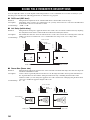
SOUND FIELD PROGRAM
DESCRIPTIONS...............................................48
For movie/video sources.......................................... 48
For music sources .................................................... 51
ADVANCED OPERATIONS ..............................52
Using the sleep timer ............................................... 52
SYSTEM OPTIONS .............................................53
Changing parameter settings ................................... 55
Input Select .............................................................. 56
Manual setup: Sound ............................................... 58
Manual setup: Basic................................................. 61
Manual setup: Option .............................................. 65
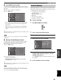
System Memory....................................................... 67
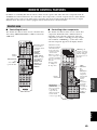
REMOTE CONTROL FEATURES ...................69
Control area ............................................................. 69
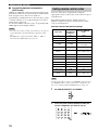
Setting remote control codes ................................... 70
Programming codes from other remote controls
(Learn) ................................................................. 72
Changing source names in the display window....... 74
Using the Macro feature .......................................... 75
Clearing function sets .............................................. 77
Clearing individual functions .................................. 78
Controlling each component.................................... 80
ZONE 2/ZONE 3
(U.S.A., CANADA, U.K., EUROPE AND
AUSTRALIA MODELS ONLY).....................81
Zone 2/Zone 3 connections...................................... 81
Remote controlling Zone 2/Zone 3.......................... 82
FRONT PANEL DISPLAY MENUS ..................84
Advanced setup menu.............................................. 84
Front panel display system options menu................ 85
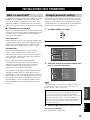
EDITING SOUND FIELD PARAMETERS ......89
What is a sound field? ............................................. 89
Changing parameter settings ................................... 89
SOUND FIELD PARAMETER
DESCRIPTIONS...............................................90
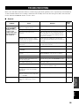
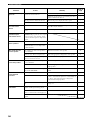
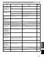
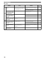
TROUBLESHOOTING .......................................95
GLOSSARY.........................................................100
Audio formats ........................................................ 100
Sound field programs............................................. 101
Audio information ................................................. 102
Video signal information ....................................... 103
PARAMETRIC EQUALIZER
INFORMATION .............................................104
SPECIFICATIONS.............................................105
CONTENTS
INTRODUCTION
PREPARATION
BASIC OPERATION
SOUND FIELD PROGRAMS
ADVANCED OPERATION
ADDITIONAL INFORMATION

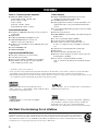
FEATURES
2
Built-in 7-channel power amplifier
◆ Minimum RMS Output Power
(0.04% THD, 20 Hz – 20 kHz, 8 Ω)
Front: 130 W + 130 W
Center: 130 W
Surround: 130 W + 130 W
Surround Back: 130 W + 130 W
Sound field features
◆ Proprietary YAMAHA technology for the creation of
sound fields
◆ THX Select
◆ Dolby Digital/Dolby Digital EX decoder
◆ DTS/DTS-ES Matrix 6.1, Discrete 6.1,
DTS Neo:6 decoder, DTS 96/24
◆ Dolby Pro Logic/Dolby Pro Logic II/Dolby Pro Logic
IIx decoder
◆ Virtual CINEMA DSP
◆ SILENT CINEMA
™
Sophisticated AM/FM tuner
◆ 40-station random access preset tuning
◆ Automatic preset tuning
◆ Preset station shifting capability (preset editing)
◆ RDS: Radio Data System receiving capability
(U.K. and Europe models only)
Other features
◆ YPAO: YAMAHA Parametric Room Acoustic
Optimizer for automatic speaker setup
◆ 192-kHz/24-bit D/A converter
◆ GUI (graphical user interface) menus that allow you to
optimize this unit to suit your individual audio/video
system
◆ 6 or 8-channel additional input jacks for discrete multi
channel input
◆ Short message function
◆ PURE DIRECT for pure fidelity sound with analog and
PCM sources
◆ S-video signal input/output capability
◆ Component video input/output capability
◆ Video signal conversion (composite video ↔
S-video → component video) capability for monitor
out
◆ Optical and coaxial digital audio signal jacks
◆ Sleep timer
◆ Cinema and music night listening mode
◆ Remote control with preset remote control codes and
learning/macro capability
◆ Zone 2/Zone 3 custom installation facility
(U.S.A., Canada, U.K., Europe and Australia models
only)
• y indicates a tip for your operation.
• Some operations can be performed by using either the buttons on the main unit or on the remote control. In cases when the button
names differ between the main unit and the remote control, the button name on the remote control is given in parentheses.
• This manual is printed prior to production. Design and specifications are subject to change in part as a result of improvements, etc. In
case of differences between the manual and product, the product has priority.
Manufactured under license from Dolby Laboratories.
“Dolby”, “Pro Logic”, “Surround EX”, and the double-D symbol
are trademarks of Dolby Laboratories.
“SILENT CINEMA” is a trademark of YAMAHA
CORPORATION.
“DTS”, “DTS-ES”, “Neo:6” and “DTS 96/24” are trademarks of
Digital Theater Systems, Inc.
THX and the THX logo are registered trademarks of THX Ltd.
Surround EX is a jointly developed technology of THX and
Dolby Laboratories, Inc. and is a trademark of Dolby
Laboratories, Inc. All rights reserved. Used under authorization.
We Want You Listening For A Lifetime
YAMAHA and the Electronic Industries Association’s Consumer Electronics Group want you to get the most out of your
equipment by playing it at a safe level. One that lets the sound come through loud and clear without annoying blaring or
distortion – and, most importantly, without affecting your sensitive hearing. Since hearing damage from loud sounds is
often undetectable until it is too late, YAMAHA and the Electronic Industries Association’s Consumer Electronics Group
recommend you to avoid prolonged exposure from excessive volume levels.
FEATURES

GETTING STARTED
3
English
INTRODUCTION
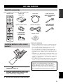
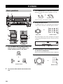
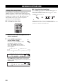
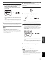
Please check that you received all of the following parts.
1 Press the part and slide the battery
compartment cover off.
2 Insert four supplied batteries (AAA, LR03)
according to the polarity markings on the
inside of the battery compartment.
3 Slide the cover back until it snaps into place.
Notes on batteries
• Change all of the batteries if you notice conditions such as the
operation range of the remote control decreases, the indicator
does not flash, or its light or display window become dim.
• Do not use old batteries together with new ones.
• Do not use different types of batteries (such as alkaline and
manganese batteries) together. Read the packaging carefully as
these different types of batteries may have the same shape and
color.
• If the batteries have leaked, dispose of them immediately. Avoid
touching the leaked material or letting it come into contact with
clothing, etc. Clean the battery compartment thoroughly before
installing new batteries.
• Do not throw away batteries with general house waste; dispose
of them correctly in accordance with your local regulations.
GETTING STARTED
Supplied accessories
CLEAR
LEARN
RE–NAME
MENU
FREQ/RDS EON MODE PTY SEEK START
REC
DISC SKIP
EFFECT
RETURN
DISPLAY
STRAIGHT
NIGHT
AUDI O
PURE DIRECT
ENTER
TITLE
A/B/C/D/E
SELECT
DTV DVR/VCR2VCR 1 DVD
V
-
AUX
CBL/SAT MD/TAPE
CD-R
PHONO TUNER CD
MULTI CH IN
VOL
+
–
3421
90
+10
ENT.
5678
POWER POWER POWER
SYSTEM
STANDBY
AVTV
SLEEP
INPUT MODE
A
B
CH
+
–
TV VOL
TV MUTE TV INPUT
MUTE
+
–
AMP
SOURCE
TV
MACROONOFF
EXIT
TOP
1
2B
THX
STANDARD SELECT EXTD. SUR
STEREO
MUSIC ENTERTAIN MOVIE
A
SPEAKERSMEMORY
Remote control Batteries (4)
(AAA, LR03)
AM loop antenna
Optimizer microphone
75-ohm/300-ohm
antenna adapter
(U.K. model only)
Speaker terminal wrench
Power cable
Indoor FM antenna
(U.K., Europe and
Australia models)
Indoor FM antenna
(U.S.A., Canada, China,
Korea, Asia and General
models)
Installing batteries in the remote
controls
1
3
2
If the remote control is without batteries for more than
2 minutes, or if exhausted batteries remain in the
remote control, the contents of the memory may be
cleared. When the memory is cleared, insert new
batteries, set up the remote control code and program
any acquired functions that may have been cleared.

CONTROLS AND FUNCTIONS
4
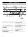
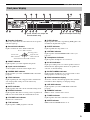
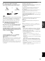
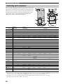
1 STANDBY/ON
Turns on this unit or sets it to the standby mode. When you
turn on this unit, you will hear a click and there will be a 6
to 7 second delay before this unit can reproduce sound.
In standby mode, this unit consumes a small amount of power in
order to receive infrared-signals from the remote control.
2 INPUT selector
Selects the input source you want to listen to or watch.
3 PURE DIRECT
Turns on or off the PURE DIRECT mode. Lights up when
turned on (see page 37).
4 Front panel display
Shows information about the operational status of this
unit.
5 PRESET/TUNING EDIT
Switches the function of PRESET/TUNING l / h
between selecting preset station numbers and tuning.
6 FM/AM
Switches the reception band between FM and AM.
7 MEMORY (MAN’L/AUTO FM)
Stores a station in the memory. Hold down this button for
more than 3 seconds to start automatic preset tuning.
8 TUNING MODE (AUTO/MAN’L MONO)
Switches the tuning mode between automatic (“AUTO”
indicator on) and manual (“AUTO” indicator off).
9 Remote control sensor
Receives signals from the remote control.
0 VOLUME
Controls the output level of all audio channels.
This does not affect the REC OUT level.
A SPEAKERS A/B
Turn on or off the set of front speakers connected to the A
and/or B terminals on the rear panel at each time the
corresponding button is pressed.
CONTROLS AND FUNCTIONS
Front panel
A
SPEAKERS
MULTI CH
B
INPUT MODE
INPUT
A/B/C/D/E
SOURCE/
REMOTE
REC OUT/ZONE 2
FM/AM
EDIT
SILENT CINEMA
S VIDEO VIDEO L
VIDEO AUX
AUDIO R OPTICAL
MEMORY
PHONES
MAN'L/AUTO FM AUTO/MAN'L MONO
PRESET/
TUNING
PRESET
/TUNING
TUNING
MODE
OPTIMIZER
MIC
TONE CONTROL STRAIGHT
EFFECT
VOLUME
PROGRAM
INPUT
PURE DIRECT
STANDBY
/ON
MD/TAPEDVD
DTV
CBL/SAT
VCR 1
CD-R
TUNER
CD
DVR/
VCR2
YPAO
1 24 0
ABC EF
DHI LKJ
3 9
PQRO
EON PTY SEEK
MODE START
RDS MODE
/FREQ
M N
ZONE ON/OFF
MAIN ZONE 2
6785
G
(U.K. and Europe models only)
(U.S.A. model)
Note

CONTROLS AND FUNCTIONS
5
English
INTRODUCTION
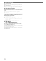
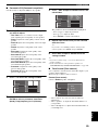
B MULTI CH INPUT
Selects the source connected to the MULTI CH INPUT
jacks. When selected, the MULTI CH INPUT source takes
priority over the source selected with INPUT (or the input
selector buttons on the remote control).
C INPUT MODE
Sets the priority (AUTO, DTS, ANALOG) for the type of
signals received when one component is connected to two
or more of this unit’s input jacks (see page 39).
D REC OUT/ZONE 2
(U.S.A., Canada, U.K., Europe and Australia
models only)
Selects the source you want to direct to the audio/video
recorder and ZONE 2 outputs independently of the source
you are listening to or watching in the main room. When
set to the SOURCE/REMOTE position, the input source is
directed to all outputs. The source in Zone 2 and the
source you record are always identical
REC OUT (other models)
Selects the source you want to direct to the audio/video
recorder independent of the source you are listening to or
watching. When set to the SOURCE/REMOTE position,
the input source is directed to all outputs.
E OPTIMIZER MIC jack
Use to connect and input audio signals from the supplied
microphone for use with the AUTO SETUP function (see
page 26).
F A/B/C/D/E
Selects one of the 5 preset station groups (A to E).
G PRESET/TUNING l / h
Selects preset station number 1 to 8 when the colon (:) is
displayed next to the band indication in the front panel
display.
Selects the tuning frequency when the colon (:) is not
displayed.
H PHONES (SILENT CINEMA) jack
Outputs audio signals for private listening with
headphones. When you connect headphones, no signals
are output to the PRE OUT jacks or to the speakers.
All Dolby Digital and DTS audio signals are mixed down
to the front left and right channels.
I VIDEO AUX jacks
Input audio and video signals from an external source such
as a game console. To reproduce source signals from these
jacks, select V-AUX as the input source.
J ZONE ON/OFF (MAIN)
(U.S.A., Canada and Australia models only)
Turns the main unit on or to the standby mode (see
page 83).
K ZONE ON/OFF (ZONE 2)
(U.S.A., Canada and Australia models only)
Turns Zone 2 on or to the standby mode (see page 83).
L TONE CONTROL
Use to adjust the bass/treble balance for the front left/right
and center channels (see page 34).
M PROGRAM
Use to select sound field programs or adjust bass/treble
balance (in conjunction with TONE CONTROL).
N STRAIGHT/EFFECT
Switches the sound fields off or on. When STRAIGHT is
selected, input signals (2-channel or multi-channel) are
output directly from their respective speakers without
effect processing.
■ U.K. and Europe models only
O RDS MODE/FREQ
Press this button when the unit is receiving an RDS station
to cycle the display mode between the PS mode, PTY
mode, RT mode, CT mode (if the station offers those RDS
data service) and/or the frequency display mode (see
page 44).
P EON
Press this button to select a radio program type (NEWS,
INFO, AFFAIRS, SPORT) to tune in automatically (see
page 46).
Q PTY SEEK MODE
Press this button to set the unit to the PTY SEEK mode
(see page 45).
R PTY SEEK START
Press this button to begin searching for a station after the
desired program type has been selected in the PTY SEEK
mode (see page 45).
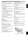
■ Opening and closing the front panel
door
When you want to use the controls behind the front panel
door, open the door by gently pressing on the lower part of
the panel. Keep the door closed when not using these
controls.
To open, press gently on the lower part of the panel.

CONTROLS AND FUNCTIONS
6
This section describes the function of each control on the
remote control used to control this unit. To operate other
components, see “REMOTE CONTROL FEATURES” on
page 69.
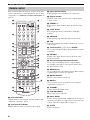
1 Infrared window
Outputs infrared control signals. Aim this window at the
component you want to operate.
2 Transmission indicator
Flashes while the remote control is sending signals.
3 Input selector buttons
Select the input source and change the control area.
4 Display window
Shows the name of the selected source component that
you can control.
5 PRESET +/–
Selects preset station numbers when this unit is in tuner
mode.
6 LIGHT button
Press to light up remote control buttons and display
window.
7 A/B/C/D/E
Selects preset groups when this unit is in tuner mode.
8 TOP
Selects the graphical user interface (GUI) mode for your
video monitor.
9 Cursor buttons k / n / l / h / ENTER
Use to select and adjust DSP program parameters or GUI
menu items.
0 RETURN
Returns to the upper directory when in the front panel
display menu mode.
A Sound field program/Numeric buttons
Use to select sound field programs or input numbers.
Use numbers 1 through 8 to select preset stations when
this unit is in tuner mode.
B MEMORY 1/2
Use to recall favorite sound field programs, YPAO settings
or additional preset stations (see page 68).
C MACRO ON/OFF
Turns the macro function on and off.
D MACRO
Use to program a series of operations for control by a
single button (see page 75).
E STANDBY
Sets this unit in the standby mode.
F SYSTEM POWER
Turns on the power of this unit.
G INPUT MODE
Sets the priority (AUTO, DTS, ANALOG) for the type of
signals received when one component is connected to two
or more of this unit’s input jacks (see page 39).
H SLEEP
Sets the sleep timer.
Remote control
CLEAR
LEARN
RE–NAME
EXIT
MENU
FREQ/RDS EON MODE PTY SEEK START
REC
DISC SKIP
EFFECT
RETURN
DISPLAY
STRAIGHT
NIGHT
AUDIO
PURE DIRECT
ENTER
TOP
TITLE
A/B/C/D/E
PRESET
SELECT
DTV DVR/VCR2VCR 1 DVD
V
-
AUX
CBL/SAT MD/TAPE
CD-R
PHONO TUNER CD
MULTI CH IN
1
2 B
THX
STANDARD SELECT
EXTD. SUR
STEREO
MUSIC ENTERTAIN MOVIE
VOL
+
–
3421
90
+10
ENT.
5678
POWER POWER POWER
SYSTEM
STANDBY
AVTV
SLEEP
INPUT MODE
A
B
CH
+
–
TV VOL
TV MUTE TV INPUT
MUTE
+
–
AMP
SOURCE
TV
MACROONOFF
A
SPEAKERSMEMORY
D
E
F
H
K
L
M
N
O
J
I
P
Q
R
S
G
9
8
0
A
2
1
4
5
7
6
3
t
U
V
W
X
B
C

CONTROLS AND FUNCTIONS
7
English
INTRODUCTION
I MULTI CH IN
Selects MULTI CH INPUT when using an external
decoder (etc.).
J SELECT k / n
Selects another component that you can control
independently of the input component selected with the
input selector buttons.
K VOL +/–
Increases or decreases the volume level.
L AMP/SOURCE/TV
Selects the component you want to control with the
remote control.
AMP: Set to this position to operate this unit.
SOURCE: Set to this position to operate the component
selected with an input selector button.
TV: Set to this position to operate the television.
To set the remote control codes for components, see
page 70.
M MUTE
Mutes the sound. Press again to restore the audio output to
the previous volume level.
N PURE DIRECT
Turns on or off PURE DIRECT mode (see page 37).
O EXIT
Use to exit the graphical user interface (GUI) mode.
P NIGHT
Turns on or off the night listening modes (see page 37).
Q DISPLAY
Use to enter into the front panel display menu mode.
R STRAIGHT/EFFECT
Switches the sound fields off or on. When STRAIGHT is
selected, input signals (2-channel or multi-channel) are
output directly from their respective speakers without
effect processing.
S EXTD. SUR
Switches between 5.1 or 6.1/7.1 channel playback of
multi-channel software.
T SPEAKERS A/B
Turn on or off the set of front speakers connected to the A
and/or B terminals on the rear panel at each time the
corresponding button is pressed.
U RE-NAME
Used to change the input source name in the display
window (see page 74).
V CLEAR
Used to clear functions acquired when using the learn,
macro and rename features, or setting remote control
codes (see page 77).
W LEARN
Used to set up the remote control code or program
functions from other remote controls (see page 72).
■ U.K. and Europe models only
X RDS tuning buttons
(Available when this unit is in tuner mode)
FREQ/RDS
Press this button when the unit is receiving an RDS station
to cycle the display between the PS mode, PTY mode, RT
mode, CT mode (if the station offers those RDS data
services) and/or the frequency display (see page 44).
EON
Press this button to select a radio program type (NEWS,
INFO, AFFAIRS, SPORT) to tune in automatically (see
page 46).
PTY SEEK MODE
Press this button to set the unit to the PTY SEEK mode
(see page 45).
PTY SEEK START
Press this button to begin searching for a station after the
desired program type has been selected in the PTY SEEK
mode (see page 45).

CONTROLS AND FUNCTIONS
8
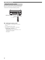
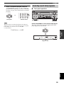
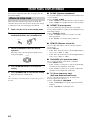
The remote control transmits a directional infrared beam.
Be sure to aim the remote control directly at the remote
control sensor on the main unit during operation.
■ Handling the remote control
• Do not spill water or other liquids on the remote
control.
• Do not drop the remote control.
• Do not leave or store the remote control in the
following types of conditions:
– high humidity such as near a bath
– high temperature such as near a heater or stove
– extremely low temperature
– dusty places
Using the remote control
A
SPEAKERS
MULTI CH
B
INPUT MODE
INPUT
TONE CONTROL STRAIGHT
EFFECT
VOLUME
PROGRAM
INPUT
STANDBY
/ON
PURE DIRECT
ZONE ON/OFF
MAIN ZONE 2
A/B/C/D/E
SOURCE
/REMOTE
REC OUT/ZONE 2
FM/AM
EDIT
PHONES
S VIDEO VIDEO L
VIDEO AUX
AUDIO R OPTICAL
MEMORY
SILENT CINEMA
MAN'L/AUTO FM AUTO/MAN'L MONO
PRESET/
TUNING
PRESET
/TUNING
TUNING
MODE
OPTIMIZER
MIC
MD/TAPEDVD
DTV
CBL/SAT
VCR 1
CD-R
TUNER
CD
DVR
/VCR2
30 30
YPAO
Approximately 6 m (20 feet)

CONTROLS AND FUNCTIONS
9
English
INTRODUCTION
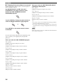
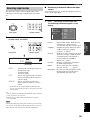
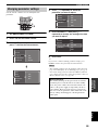
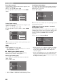
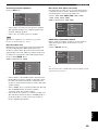
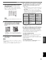
1 Decoder indicators
When any of this unit’s decoders function, the respective
indicator lights up.
2 Sound field indicators
Light to indicate the active DSP sound fields.
3 NIGHT indicator
Lights up when you select night listening mode.
4 Input source indicators
A cursor lights to show the current input source.
5 CINEMA DSP indicator
Lights up when you select a CINEMA DSP sound field
program.
6 YPAO indicator
Lights up during the auto setup procedure and when the
auto setup speaker settings are used without any
modifications.
7 AUTO indicator
Lights up when this unit is in the automatic tuning mode.
8 STEREO indicator
Lights up when this unit is receiving a stereo signal for an
FM stereo broadcast while the AUTO indicator is lit.
9 VOLUME level indicator
Indicates the volume level.
0 THX indicator
Lights up when a THX program is selected.
A PCM indicator
Lights up when this unit is reproducing PCM (pulse code
modulation) digital audio signals.
B SLEEP indicator
Lights up while the sleep timer is on.
C VIRTUAL indicator
Lights up when Virtual CINEMA DSP is active (see
page 38).
D Headphones indicator
Lights up when headphones are connected.
E SP A B indicators
Light up according to the set of front speakers selected.
Both indicators light up when both sets of speakers are
selected, or when bi-wiring.
F SILENT CINEMA indicator
Lights up when headphones are connected and a sound
field program is selected (see page 34).
G Multi-information display
Shows the current sound field program name and other
information when adjusting or changing settings.
H HiFi DSP indicator
Lights up when you select a HiFi DSP sound field
program.
I MEMORY indicator
Blinks to show a station can be stored.
J TUNED indicator
Lights up when this unit is tuned into a station.
K MUTE indicator
Blinks while the MUTE function is on.
Front panel display
V–AUX
DVR/VCR2
VCR 1
CBL/SAT
DTV DVD
MD/TAPE
CD–R CD TUNER
PHONO
96
24
NIGHT
VIRTUAL
ZONE2
ZONE3
ZONE4
SLEEP
YPAO
HiFi DSP
STEREO
TUNED
EON
AUTO
MEMORY
MUTE
VOLUME
DIGITAL
PL
MATRIX
DISCRETE
PCM
THX
PL
EX
SILENT
CINEMA
A B
SP
LFE
ft
mS
dB
96/24
LL C R
SL SB SR
PL x
PS PTY RT CT
PTY
HOLD
dB
AFGHK
135678
BE
2
C
9
DIJ
PQ
LM
4
NO0
(U.S.A., Canada, U.K., Europe and
Australia models only)
(U.K. and Europe models only)
Presence DSP sound field
Listening position
Left surround
DSP sound field
Right surround
DSP sound field
Surround/surround back DSP sound field

CONTROLS AND FUNCTIONS
10
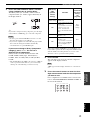
L 96/24 indicator
Lights up when a DTS 96/24 signal is input to this unit.
M LFE indicator
Lights up when the input signal contains an LFE signal.
N Input channel indicators
Indicate the channel components of current digital input
signal.
O Presence and surround back speaker
indicators
Indicate the connection of presence and/or surround back
speakers when using the Auto Setup setting (page 26) or
Speaker Level setting (page 64).
P ZONE 2/ZONE 3 indicators
(U.S.A., Canada, U.K., Europe and Australia
models only)
Light up when Zone 2 or Zone 3 power is on.
Q RDS indicators
(U.K. and Europe models only)
The name(s) of the RDS data offered by the currently
received RDS station light(s) up.
EON lights up when an RDS station that offers the EON
data service is being received.
PTY HOLD lights up while searching for stations in the
PTY SEEK mode.

CONTROLS AND FUNCTIONS
11
English
INTRODUCTION
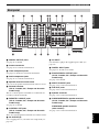
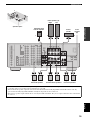
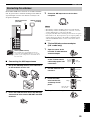
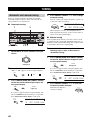
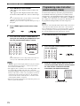
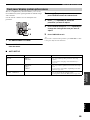
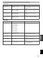
1 DIGITAL OUTPUT jacks
See page 21 for details.
2 Antenna terminals
See page 23 for connection information.
3 Video component jacks
See pages 18 and 20 for connection information.
4 Audio component jacks
See page 21 for connection information.
5 Speaker terminal wrench hook
Use to store the speaker terminal wrench when not in use.
6 RS-232C terminal
(U.S.A., Canada, U.K., Europe and Australia
models only)
This is a control expansion terminal for commercial use.
Consult you dealer for details.
7 REMOTE 1/2 IN/OUT jacks
(U.S.A., Canada, U.K., Europe and Australia
models only)
See page 81 for details.
8 CONTROL OUT jacks
(U.S.A., Canada, U.K., Europe and Australia
models only)
These are control expansion terminals for commercial use.
9 AC OUTLET(S)
Use to supply power to your other A/V components (see
page 24).
0 AC INLET
Use this inlet to plug in the supplied power cable (see
page 24).
A DIGITAL INPUT jacks
See pages 18, 20 and 21 for details.
B ZONE 2/ZONE 3 OUTPUT jacks
(U.S.A., Canada, U.K., Europe and Australia
models only)
See page 81 for details.
C MULTI CH INPUT jacks
See page 19 for connection information.
D PRE OUT jacks
See page 22 for connection information.
E Speaker terminals
See page 13 for connection information.
F PRESENCE/ZONE 2 speaker terminals
(U.S.A., Canada, U.K., Europe and Australia
models only)
PRESENCE speaker terminals
(other models)
See page 13 for connection information.
Rear panel
GND
SPEAKERS
FRONT
CENTER
PRE OUT
SURROUND
SURROUND BACK SINGLE
R
R
L
R
R
L
L
L
MONITOR
AUDIOVIDEO
S VIDEO
DVD
DTV
CBL/
SAT
VIDEO
IN
OUT
OUT
DVR/VCR 2
VCR 1
ZONE 2
R
L
IN
CENTERSUB WOOFER
MULTI CH INPUTOUTPUT
AUDIO
R
L
IN
(
PLAY
)
IN
(
PLAY
)
OUT
(
REC
)
OUT
(
REC
)
CD-R
MD/TAPE
CD
PHONO
SURROUND
TUNER
75Ω
UNBAL.
AM
ANT
GND
FM ANT
DIGITAL OUTPUT
DIGITAL INPUT
OPTICAL
MD
/
TAPE
CD-R
DVD
DTV
CBL/SAT
CD
CD
DVD
COAXIAL
+
–
+
–
+
–
+
+
––
–
+
+
+
+
+
–
–
–
–
A
B
RS-232C
DVR/
VCR 2
CONTROL OUT
REMOTE
IN IN OUT
21
OUT
1
2
COMPONENT VIDEO
P
R
MONITOR
OUT
P
B
Y
DVD
DTVDTV
CBL/
SAT
+12V 15mA MAX.
PRESENCE/ZONE 2
ZONE 3
FRONT (6 ch)/ SB (8 ch)
AC OUTLETS
AC IN
FRONT
SURROUND
SUB WOOFER
SURROUND BACK /PRESENCE
CENTER
R
R
L
L
R
L
SINGLE
(SB)
1234678 9
FEDCB
A
0
5
(U.S.A. model)

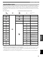
SPEAKER SETUP
12
+
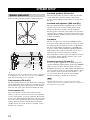
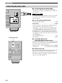
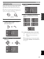
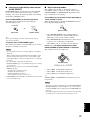
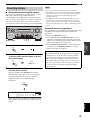
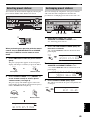
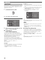
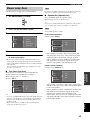
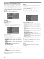
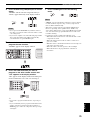
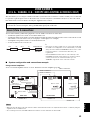
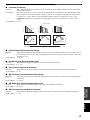
For best results, place the speakers as illustrated below.
.
y
The illustrations show the standard speaker setting recommended
by the ITU-R (see page 102). You can use it to enjoy CINEMA
DSP, multi-channel audio sources, and THX.
Front speakers (FR and FL)
The front speakers are used for the main source sound plus
effect sounds. Place these speakers an equal distance from
the ideal listening position. The distance of each speaker
from each side of the video monitor should be the same.
Center speaker (C)
The center speaker is for the center channel sounds
(dialog, vocals, etc.). If for some reason it is not practical
to use a center speaker, you can do without it. Best results,
however, are obtained with the full system. Align the front
face of the center speaker with the front face of your video
monitor. Place the speaker centrally between the front
speakers and as close to the monitor as possible, such as
directly over or under it.
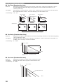
Surround speakers (SR and SL)
The surround speakers are used for effect and surround
sounds. Place these speakers behind your listening
position, facing slightly inwards, about 1.8 m (6 ft) above
the floor.
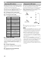
Surround back speakers (SBR and SBL)
The surround back speakers supplement the surround
speakers and provide for more realistic front-to-back
transitions. Place these speakers directly behind the
listening position and at the same height as the surround
speakers. They should be positioned at least 30 cm (12 in)
apart. Ideally, they should be positioned at the same width
as the front speakers.
Subwoofer
The use of a subwoofer, such as the YAMAHA Active
Servo Processing Subwoofer System, is effective not only
for reinforcing bass frequencies from any or all channels,
but also for high fidelity reproduction of the LFE (low-
frequency effect) channel included in Dolby Digital and
DTS software. The position of the subwoofer is not so
critical, because low bass sounds are not highly
directional. But it is better to place the subwoofer near the
front speakers. Turn it slightly toward the center of the
room to reduce wall reflections.
Presence speakers (PR and PL)
Presence speakers supplement the sound from the front
speakers with extra ambient effects produced by CINEMA
DSP (see page 48). These effects include sounds that
filmmakers intend to locate a little farther back behind the
screen in order to create more theater-like ambience. Place
these speakers at the front of the room about 0.5 - 1 m
(1 - 3 ft) outside the front speakers, facing slightly
inwards, and about 1.8 m (6 ft) above the floor.
Surround back and presence speakers do not output sound
simultaneously. You can set to prioritize either set of speakers in
the Sound menu (see page 60).
SPEAKER SETUP
Speaker placement
More than 30 cm (12 in)
60˚
30˚
PL
PR
SBR
SBL
FL
FR
C
SL
SR
SR
80˚
SL
1.8 m (6 ft)
1.8 m (6 ft)
Note

13
English
SPEAKER SETUP
PREPARATION
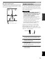
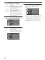
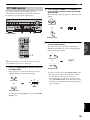
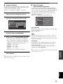
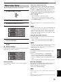
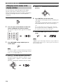
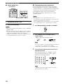
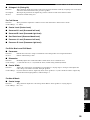
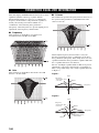
■ Di-pole speaker layout
Either di-pole or direct radiating speaker types can be used
for THX surround. If you choose di-pole speakers, please
place the surround and surround back speakers according
to the speaker layout below.
Be sure to connect the left channel (L), right channel (R),
“+” (red) and “–” (black) properly. If the connections are
faulty, no sound will be heard from the speakers, and if the
polarity of the speaker connections is incorrect, the sound
will be unnatural and lack bass.
• If you will use 6 ohm speakers, be sure to set
this unit’s speaker impedance setting to
6 ohms before using (see page 25). If you will
use 8 ohm speakers, use this unit’s initial
setting for speaker impedance.
• Before connecting the speakers, make sure that this
unit is disconnected from the power source.
• Do not let the bare speaker wires touch each other or do
not let them touch any metal part of this unit. This
could damage this unit and/or speakers.
• Use magnetically shielded speakers. If this type of
speaker still creates interference with the monitor,
place the speakers away from the monitor.
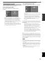
A speaker cord is actually a pair of insulated cables
running side by side. One cable is colored or shaped
differently, perhaps with a stripe, groove or ridges.
Connect the striped (grooved, etc.) cable to the “+” (red)
terminals on this unit and your speaker. Connect the plain
cable to the “–” (black) terminals.
1 Remove approximately 10 mm (3/8 in) of
insulation from each of the speaker cables.
2 Twist the exposed wires of the cable together
to prevent short circuits.
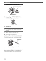
3 Loosen the knob.
The supplied speaker terminal wrench is useful for
loosening or tightening knobs.
4 Insert one bare wire into the hole in the side
of each terminal.
FL
SR
SL
FR
C
SBR
SBL
30˚ 30˚
: Di-pole speaker
: Direction of di-pole speaker
Speaker connections
CAUTION
10 mm (3/8 in)
1
2

14
SPEAKER SETUP
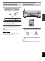
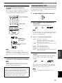
5 Tighten the knob to secure the wire.
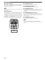
■ Connecting to PRESENCE/ZONE 2 or
PRESENCE speaker terminals
1 Open the tab.
2 Insert one bare wire into the hole of each
terminal.
3 Return the tab to secure the wire.
■ Banana plug connections
(With the exception of U.K., Europe and Asia models)
First, tighten the knob and then insert the banana plug
connector into the end of the corresponding terminal.
y
You can also use banana plugs with the PRESENCE/ZONE 2 and
PRESENCE speaker terminals. Open the tab, then insert one
banana plug connector into the hole of each terminal. Do not
attempt to close the tabs after connecting the banana plugs.
Red: positive (+)
Black: negative (–)
5
4
3
Speaker terminal wrench
2
1
3
Banana plug
(With the exception of U.K., Europe
and Asia models)

15
English
SPEAKER SETUP
PREPARATION
SPEAKERS
FRONT
CENTER
PRE OUT
SURROUND
SURROUND BACK SINGLE
R
R
L
R
R
L
L
L
+
–
+
–
+
–
+
+
––
–
+
+
+
+
+
–
–
–
–
A
B
PRESENCE/ZONE 2
FRONT
SURROUND
SUB WOOFER
SURROUND BACK /PRESENCE
CENTER
R
R
L
L
R
L
SINGLE
(SB)
231
7 8 65 109
4
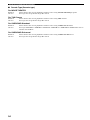
Center
speaker
Front speakers (A)
Surround back speakers
LeftRight
LeftRight LeftRight
Surround speakers
Front
speakers
(B)
1
2
3
4
5
6
9
10
8
7
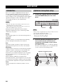
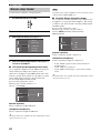
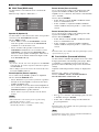
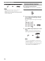
Speaker layout
(U.S.A. model)
LeftRight
Presence speakers
• You can connect both surround back and presence speakers to this unit, but they do not output sound simultaneously.You can set
to prioritize either set of speakers in the Sound menu (see page 60).
• The surround back speakers output the surround back channel included in Dolby Digital EX and DTS-ES software and only
operate when the Dolby Digital EX, DTS-ES or Dolby Pro Logic IIx decoder is turned on.
• The presence speakers output ambient effects created by the DSP sound fields. They do not output sound when other sound fields
are selected.
Subwoofer with
built-in amplifier

16
SPEAKER SETUP
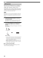
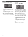
■ FRONT terminals
Connect one or two speaker systems to these terminals. If
you use only one speaker system, connect it to either of
the FRONT A or B terminals.
The Canada model cannot output to two separate speaker systems
simultaneously.
Bi-wired connection
The unit also allows you to make bi-wired connections to
one speaker system. Use two pairs of speaker cables for
each speaker (one pair for the woofer and one pair for the
tweeter/mid-range). To use the bi-wired connections, press
SPEAKERS A and SPEAKERS B on the front panel so
that both SP A and B light up on the front panel display.
■ CENTER terminals
Connect a center speaker to these terminals.
■ SURROUND terminals
Connect surround speakers to these terminals.
■ SUBWOOFER jack
Connect a subwoofer with a built-in amplifier, such as the
YAMAHA Active Servo Processing Subwoofer System,
to this jack.
■ SURROUND BACK terminals
Connect surround back speakers to these terminals. If you
only connect one surround back speaker, connect it to the
left (L) terminals.
■ PRESENCE terminals
Connect presence speakers to these terminals.
(U.S.A., Canada, U.K., Europe and Australia models only)
You can also use these terminals to connect Zone 2 speakers (see
page 66).
Note
Bi-wired connection
FRONT
R
L
+
–
+
–
+
+
–
–
A
B
This unit
Note

CONNECTIONS
17
English
PREPARATION
Do not connect this unit or other components to the mains
power until all connections between components are
complete.
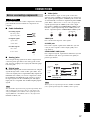
■ Cable indications
■ Analog jacks
You can input analog signals from audio components by
connecting audio pin cables to the analog jacks on this
unit. Connect red plugs to the right jacks and white plugs
to the left jacks.
■ Digital jacks
This unit has digital jacks for direct transmission of digital
signals through either coaxial or fiber optic cables. You
can use the digital jacks to input PCM, Dolby Digital and
DTS bitstreams. When you connect components to both
the COAXIAL and OPTICAL jacks, priority is given to
the input signals from the COAXIAL jack. All digital
input jacks are compatible with 96-kHz sampling digital
signals.
This unit handles digital and analog signals independently. Thus
audio signals input to the analog jacks are only output to the
analog OUT (REC) jacks. Likewise audio signals input to the
digital (OPTICAL or COAXIAL) jacks are only output to the
DIGITAL OUTPUT jacks.
■ Video jacks
This unit has three types of video jacks. Connection
depends on the availability of input jacks on your monitor.
The signals input through the S VIDEO jacks on this unit
are automatically converted for output through the VIDEO
jacks. When “Video Conv.” is set to “On” (see page 65),
signals input through the VIDEO jacks can be output
through the S VIDEO and COMPONENT VIDEO jacks.
Likewise, signals input through the S VIDEO jacks can
also be output through the COMPONENT VIDEO jacks.
VIDEO jack
For conventional composite video signals.
S VIDEO jack
For S-video signals, separated into luminance (Y) and
color (C) video signals to achieve high-quality color
reproduction.
COMPONENT VIDEO jacks
For component signals, separated into luminance (Y) and
color difference (PB, PR) to provide the best quality in
picture reproduction.
When signals are input through both the S VIDEO and VIDEO
jacks, signals input through the S VIDEO jack have priority.
CONNECTIONS
Before connecting components
Note
CAUTION
S
V
O
V
V
V
L
R
C
left analog cables
right analog cables
optical cables
coaxial cables
video cables
S-video cables
For analog signals
For digital signals
For video signals
Note
VIDEO
S VIDEO
COMPONENT VIDEO
P
R
P
B
Y
S VIDEO
VIDEO
COMPONENT
VIDEO
Signal flow inside this unit
Only when “Video Conv.” is set to “On”
(see page 65)
Output
(MONITOR OUT)
Input

18
CONNECTIONS
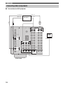
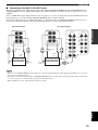
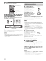
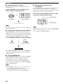
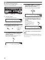
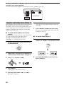
■ Connections for DVD playback
Connecting video components
DVD
DVD
MONITOR
AUDIOVIDEO
S VIDEO
DVD
VIDEO
R
L
COMPONENT VIDEO
P
R
MONITOR
OUT
P
B
Y
DVD
C
O
LR
DVD player
Video
monitor
(U.S.A. model)
Optical out Video out
Audio out
Video in
Coaxial out
La pagina si sta caricando...
La pagina si sta caricando...
La pagina si sta caricando...
La pagina si sta caricando...
La pagina si sta caricando...
La pagina si sta caricando...
La pagina si sta caricando...
La pagina si sta caricando...
La pagina si sta caricando...
La pagina si sta caricando...
La pagina si sta caricando...
La pagina si sta caricando...
La pagina si sta caricando...
La pagina si sta caricando...
La pagina si sta caricando...
La pagina si sta caricando...
La pagina si sta caricando...
La pagina si sta caricando...
La pagina si sta caricando...
La pagina si sta caricando...
La pagina si sta caricando...
La pagina si sta caricando...
La pagina si sta caricando...
La pagina si sta caricando...
La pagina si sta caricando...
La pagina si sta caricando...
La pagina si sta caricando...
La pagina si sta caricando...
La pagina si sta caricando...
La pagina si sta caricando...
La pagina si sta caricando...
La pagina si sta caricando...
La pagina si sta caricando...
La pagina si sta caricando...
La pagina si sta caricando...
La pagina si sta caricando...
La pagina si sta caricando...
La pagina si sta caricando...
La pagina si sta caricando...
La pagina si sta caricando...
La pagina si sta caricando...
La pagina si sta caricando...
La pagina si sta caricando...
La pagina si sta caricando...
La pagina si sta caricando...
La pagina si sta caricando...
La pagina si sta caricando...
La pagina si sta caricando...
La pagina si sta caricando...
La pagina si sta caricando...
La pagina si sta caricando...
La pagina si sta caricando...
La pagina si sta caricando...
La pagina si sta caricando...
La pagina si sta caricando...
La pagina si sta caricando...
La pagina si sta caricando...
La pagina si sta caricando...
La pagina si sta caricando...
La pagina si sta caricando...
La pagina si sta caricando...
La pagina si sta caricando...
La pagina si sta caricando...
La pagina si sta caricando...
La pagina si sta caricando...
La pagina si sta caricando...
La pagina si sta caricando...
La pagina si sta caricando...
La pagina si sta caricando...
La pagina si sta caricando...
La pagina si sta caricando...
La pagina si sta caricando...
La pagina si sta caricando...
La pagina si sta caricando...
La pagina si sta caricando...
La pagina si sta caricando...
La pagina si sta caricando...
La pagina si sta caricando...
La pagina si sta caricando...
La pagina si sta caricando...
La pagina si sta caricando...
La pagina si sta caricando...
La pagina si sta caricando...
La pagina si sta caricando...
La pagina si sta caricando...
La pagina si sta caricando...
La pagina si sta caricando...
-
 1
1
-
 2
2
-
 3
3
-
 4
4
-
 5
5
-
 6
6
-
 7
7
-
 8
8
-
 9
9
-
 10
10
-
 11
11
-
 12
12
-
 13
13
-
 14
14
-
 15
15
-
 16
16
-
 17
17
-
 18
18
-
 19
19
-
 20
20
-
 21
21
-
 22
22
-
 23
23
-
 24
24
-
 25
25
-
 26
26
-
 27
27
-
 28
28
-
 29
29
-
 30
30
-
 31
31
-
 32
32
-
 33
33
-
 34
34
-
 35
35
-
 36
36
-
 37
37
-
 38
38
-
 39
39
-
 40
40
-
 41
41
-
 42
42
-
 43
43
-
 44
44
-
 45
45
-
 46
46
-
 47
47
-
 48
48
-
 49
49
-
 50
50
-
 51
51
-
 52
52
-
 53
53
-
 54
54
-
 55
55
-
 56
56
-
 57
57
-
 58
58
-
 59
59
-
 60
60
-
 61
61
-
 62
62
-
 63
63
-
 64
64
-
 65
65
-
 66
66
-
 67
67
-
 68
68
-
 69
69
-
 70
70
-
 71
71
-
 72
72
-
 73
73
-
 74
74
-
 75
75
-
 76
76
-
 77
77
-
 78
78
-
 79
79
-
 80
80
-
 81
81
-
 82
82
-
 83
83
-
 84
84
-
 85
85
-
 86
86
-
 87
87
-
 88
88
-
 89
89
-
 90
90
-
 91
91
-
 92
92
-
 93
93
-
 94
94
-
 95
95
-
 96
96
-
 97
97
-
 98
98
-
 99
99
-
 100
100
-
 101
101
-
 102
102
-
 103
103
-
 104
104
-
 105
105
-
 106
106
-
 107
107


Yamaha RX-V2500 Manuale del proprietario
- Categoria
- Ricevitori AV
- Tipo
- Manuale del proprietario
in altre lingue
- English: Yamaha RX-V2500 Owner's manual
- français: Yamaha RX-V2500 Le manuel du propriétaire
- Deutsch: Yamaha RX-V2500 Bedienungsanleitung
- Nederlands: Yamaha RX-V2500 de handleiding
- dansk: Yamaha RX-V2500 Brugervejledning
- svenska: Yamaha RX-V2500 Bruksanvisning
- Türkçe: Yamaha RX-V2500 El kitabı
- română: Yamaha RX-V2500 Manualul proprietarului
Documenti correlati
-
Yamaha RX-V1800 Manuale del proprietario
-
Yamaha RX-497 Manuale del proprietario
-
Yamaha RX-797 Manuale del proprietario
-
-
-
-
Yamaha RX-V3800 Manuale del proprietario
-
-
-
Yamaha RX V2700 - AV Network Receiver Manuale del proprietario