Sony DSBK-1501 Manuale utente
- Categoria
- Apparecchiature musicali supplementari
- Tipo
- Manuale utente
La pagina sta caricando ...

For the customers in the USA
This equipment has been tested and found to comply with
the limits for a Class A digital device, pursuant to Part 15 of
the FCC Rules. These limits are designed to provide
reasonable protection against harmful interference when the
equipment is operated in a commercial environment. This
equipment generates, uses, and can radiate radio frequency
energy and, if not installed and used in accordance with the
instruction manual, may cause harmful interference to radio
communications. Operation of this equipment in a residential
area is likely to cause harmful interference in which case the
user will be required to correct the interference at his own
expense.
You are cautioned that any changes or modifications not
expressly approved in this manual could void your authority
to operate this equipment.
The shielded interface cable recommended in this manual
must be used with this equipment in order to comply with the
limits for a digital device pursuant to Subpart B of Part 15 of
FCC Rules.
This device complies with Part 15 of the FCC Rules.
Operation is subject to the following two conditions: (1) This
device may not cause harmful interference, and (2) this
device must accept any interference received, including
interference that may cause undesired operation.
For the customers in Canada
This Class A digital apparatus complies with Canadian ICES-
003.
For the customers in Europe
This product with the CE marking complies with the EMC
Directive (89/336/EEC) issued by the Commission of the
European Community.
Compliance with this directive implies conformity to the
following European standards:
• EN55103-1: Electromagnetic Interference (Emission)
• EN55103-2: Electromagnetic Susceptibility (Immunity)
This product is intended for use in the following
Electromagnetic Environment(s):
E1 (residential), E2 (commercial and light industrial), E3
(urban outdoors) and E4 (controlled EMC environment, ex.
TV studio).
Pour les utilisateurs au Canada
Cet appareil numérique de la classe A est conforme à la
norme NMB-003 du Canada.
Pour les clients européens
Ce produit portant la marque CE est conforme à la Directive
sur la compatibilité électromagnétique (EMC) (89/336/CEE)
émise par la Commission de la Communauté européenne.
La conformité à cette directive implique la conformité aux
normes européennes suivantes:
• EN55103-1: Interférences électromagnétiques (émission)
• EN55103-2: Sensibilité électromagnétique (immunité)
Ce produit est prévu pour être utilisé dans les
environnements électromagnétiques suivants:
E1 (résidentiel), E2 (commercial et industrie légère), E3
(urbain extérieur) et E4 (environnement EMC contrôlé ex.
studio de télévision).
Für Kunden in Europa
Dieses Produkt besitzt die CE-Kennzeichnung und erfüllt die
EMV-Direktive (89/336/EEC) der EG-Kommission.
Die Erfüllung dieser Direktive bedeutet Konformität für die
folgenden Europäischen Normen:
• EN55103-1: Elektromagnetische Interferenz (Emission)
• EN55103-2: Elektromagnetische Empfindlichkeit
(Immunität)
Dieses Produkt ist für den Einsatz unter folgenden
elektromagnetischen Bedingungen ausgelegt:
E1 (Wohnbereich), E2 (kommerzieller und in beschränktem
Maße industrieller Bereich), E3 (Stadtbereich im Freien) und
E4 (kontrollierter EMV-Bereich, z.B. Fernsehstudio).
Per i clienti in Europa
Questo prodotto recante il marchio CE è conforme alla
direttiva sulla compatibilità elettromagnetica (EMC) (89/336/
CEE) emessa dalla Commissione della Comunità Europea.
La conformità a questa direttiva implica la conformità alle
seguenti normative europee:
• EN55103-1: Interferenza elettromagnetica (Emissione)
• EN55103-2: Sensibilità ai disturbi elettromagnetici
(Immunità)
Questo prodotto è destinato all’uso nei seguenti ambienti
elettromagnetici:
E1 (residenziali), E2 (commerciali e industriali leggeri), E3
(esterni urbani) e E4 (ambienti EMC controllati, ad esempio
studi televisivi).
La pagina sta caricando ...

4
The DSBK-1501 Digital Input/Output Board is an
optional board for the DSR-1500/1500P Digital
Videocassette Recorder.
The DSBK-1501 optional board is provided with three
fastening screws (M3 × 6).
Refer to the DSR-1500/1500P Operating Instructions
for information on connecting and operating the DSR-
1500/1500P fitted with the DSBK-1501.
La carte d’entrée/sortie numérique DSBK-1501 est une
carte optionnelle prévue pour le magnétoscope
enregistreur numérique DSR-1500/1500P.
La carte optionnelle DSBK-1501 est dotée de trois vis
de fixation (M3 × 6). Voir le mode d’emploi du DSR-
1500/1500P pour les informations sur le raccordement
et le fonctionnement du DSR-1500/1500P équipé de la
carte DSBK-1501.
/Overview/Aperçu/Kurzbeschreibung/
Descrizione
Die Digital-E/A-Karte DSBK-1501 ist eine Option für
den Digitalvideorecorder DSR-1500/1500P.
Die optionale Karte verfügt über drei
Befestigungsschrauben (M3 × 6). Näheres über
Anschluß und Betrieb des DSR-1500/1500P mit
installierter DSBK-1501 finden Sie in der
Bedienungsanleitung des Videorecorders.
La scheda di ingresso/uscita digitale DSBK-1501 è una
scheda opzionale per il videoregistratore digitale DSR-
1500/1500P.
La scheda opzionale DSBK-1501 viene fornita con tre
viti di fissaggio (M3 × 6).
Per ulteriori informazioni sul collegamento e
sull’azionamento del DSR-1500/1500P con montata la
scheda DSBK-1501, consultare il Manuale di
istruzioni per l’uso del DSR-1500/1550P.

5
Caution
If this option is installed incorrectly, personal injury or
damage to peripheral items may occur due to fire,
shock, or other accidental circumstances. To avoid
such risks, installation should be performed by
qualified service personnel.
Attention
L’installation incorrecte de cette option pourra donner
lieu à des blessures personnelles ou bien des
dommages à des éléments périphériques suite à un feu,
une décharge électrique ou d’autres circonstances
accidentelles. Pour éviter de tels risques, faites faire
l’installation par un personnel de service qualifié.
/
Installation/Installation/Installation/
Installazione
Vorsicht
Bei falscher Installation dieser Option besteht die
Gefahr von Verletzungen bzw. Beschädigung von
Peripheriekomponenten durch Brand, Stromschlag
oder sonstige Probleme. Überlassen Sie daher
Installationsarbeiten ausschließlich qualifiziertem
Fachpersonal.
Cautela
Se questa opzione non viene installata correttamente,
si possono verificare lesioni alle persone o danni a
unità periferiche dovuti a incendi, scosse elettriche e
altri incidenti. Per evitare tali rischi, l’installazione
dovrebbe essere eseguita da personale tecnico
qualificato.
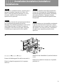
1
Remove the blanking panel (b) and the rear panel (a).
Retirez la plaque de suppression (b) et le panneau
arrière (a).
a
b
Nehmen Sie das Abdeckblech (b) und die Rückseite
(a) ab.
Rimuovere il pannello di chiusura (b) e il pannello
posteriore (a).

6
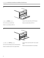
2
Pull out the lower board (SSS-10).
Retirez la carte inférieure (SSS-10).
SSS-10
Ziehen Sie die unterste Karte (SSS-10) heraus.
Estrarre la scheda inferiore (SSS-10).
3
Pull out the second board (DVP-19) from the bottom.
Retirez la seconde carte (DVP-19) à partir du bas.
DVP-19
Ziehen Sie die zweite Karte (DVP-19) von unten
heraus.
Estrarre la seconda scheda (DVP-19) dal basso.
/Installation/Installation/Installation/Installazione

7
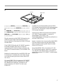
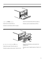
4
Plug the connectors on the DSBK-1501 board into the
connectors on the edge of the board (DVP-19) you
have just pulled out, then fasten the DSBK-1501 board
with the screws.
If the DSBK-1503 board and i.DV IN/OUT connector
are already installed, remove the i.DV IN/OUT
connector from the connector adapter, and refit to the
i.DV IN/OUT connector section (c) of the DSBK-1501
board.
Branchez les connecteurs de la carte DSKB-1501 dans
le connecteurs à l’extrémité de la carte (DVP-19) que
vous venez de retirer, puis fixez la carte DSBK-1501
avec les vis.
Si la carte DSBK-1501 et le connecteur i.DV IN/OUT
sont déjà installés, retirez le connecteur i.DV IN/OUT
de l’adaptateur de connecteur, et réajustez-le à la
section connecteur i.DV IN/OUT (c) de la carte
DSBK-1501.
DVP-19
DSBK-1501
c
Verbinden Sie die Steckverbinder an Karte DSBK-
1501 mit den Steckverbindern an der herausgezogenen
Karte (DVP-19). Befestigen Sie dann Karte DSBK-
1501 mit den Schrauben.
Sind die Karte DSBK-1503 und der Steckverbinder
i.DV IN/OUT bereits installiert, so trennen Sie
Steckverbinder i.DV IN/OUT vom
Steckverbinderadapter und bringen ihn am Bereich (c)
an Karte DSBK-1501 an.
Inserire i connettori che si trovano sulla scheda DSBK-
1501 nei connettori situati sul bordo della scheda
(DVP-19) appena estratta, quindi fissare la scheda
DSBK-1501 con le viti.
Se la scheda DSBK-1503 e il connettore i.DV /IN/
OUT sono già stati installati, rimuovere il connettore
i.DV /IN/OUT dall’adattore relativo e rimontare la
sezione del connettore i.DV /IN/OUT (c) della scheda
DSBK-1501.

8
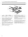
5
Insert the DVP-19 board and DSBK-1501 board,
aligning them with the guides (d), and plug the
connectors (e) of the DVP-19 board into the
connectors (f) on the DSR-1500/1500P unit.
At this point, align the positioning holes (g) with the
studs at the edge of the unit.
Insérez la carte DVP-19 et la carte DSBK-1501, en les
alignant sur les guides (d) et branchez les connecteurs
(e) de la carte DVP-19 dans ceux (f) du DSR-1500/
1500P.
Alignez alors les trous de positionnement (g) sur les
goujons à l’extrémité de l’appareil.
f
e
e
d
g
g
DVP-19
DSBK-1501
f
Schieben Sie die Karte DVP-19 und DSBK-1501 in
die Führungen (d) und führen Sie sie in den
Videorecorder ein. Verbinden Sie die Steckverbinder
(e) der Karte DVP-19 mit den Steckverbindern (f) am
DSR-1500/1500P.
Fluchten Sie nun die Positionieröffnungen (g) mit den
Gewindestutzen am Rand des Geräts.
Inserire le schede DVP-19 e DSBK-1501, allineandole
con le guide (d) e inserire i connettori (e) che si
trovano sulla scheda DVP-19 nei connettori (f) che si
trovano sull’unità DSR-1500/1500P.
A questo punto, allineare i fori di posizionamento (g)
con i perni che si trovano al bordo dell’unità.
/Installation/Installation/Installation/Installazione

9
6
Replace the lower board (SSS-10).
Remettez la carte inférieure (SSS-10) en place.
SSS-10
Setzen Sie die unterste Karte (SSS-10) wieder ein.
Rimettere a posto la scheda inferiore (SSS-10).
7
Replace the rear panel. Fasten the screw (h).
Remettez le panneau arrière en place. Serrez la vis (h).
h
Bringen Sie die Rückseite an, und ziehen Sie die
Schraube (h) an.
Rimettere a posto il pannello posteriore. Serrare le viti
(h).
La pagina sta caricando ...
La pagina sta caricando ...
La pagina sta caricando ...
-
 1
1
-
 2
2
-
 3
3
-
 4
4
-
 5
5
-
 6
6
-
 7
7
-
 8
8
-
 9
9
-
 10
10
-
 11
11
-
 12
12


Sony DSBK-1501 Manuale utente
- Categoria
- Apparecchiature musicali supplementari
- Tipo
- Manuale utente
in altre lingue
- English: Sony DSBK-1501 User manual
- français: Sony DSBK-1501 Manuel utilisateur
- Deutsch: Sony DSBK-1501 Benutzerhandbuch
- 日本語: Sony DSBK-1501 ユーザーマニュアル
Documenti correlati
-
Sony DSBK-1504 Manuale utente
-
-
-
-
Sony ICD-SX2000 Informazioni importanti
-
Sony DVP-NS305 Istruzioni per l'uso
-
Sony DVPF25 Manuale del proprietario
-
Sony DVP-PQ2 Istruzioni per l'uso
-
Sony DVP-PQ1 Istruzioni per l'uso
-