
GCE HEALTHCARE
CENTRAL GAS SUPPLY SYSTEM
CENTRÁLNÍ ROZVODOVÝ SYSTÉM
SYSTEME CENTRAL DE DISTRIBUTION DE GAZ
CENTRALGASANLÄGGNING
SISTEMA CENTRALIZODO DE SUMINISTRO DE GAS
CENTRALNY SYSTEM ZASILANIA GAZEM
CENTRAAL GASTOEVOERSYSTEEM
CENTRALE EROGAZIONE GAS MEDICALE
KÖZPONTI GÁZELLÁTÓ RENDSZER
ZENTRALES GASVERSORGUNGSSYSTEM
MM40 HP UNIT
EN
CS
FR
SV
ES
PL
NL
INSTRUCTION FOR USE
NÁVOD K POUŽITÍ
MODE D‘EMPLOI
ANVÄNDARANVISNING
INSTRUCCIONES DE USE
INSTRUKCJA OBSŁUGI
GEBRUIKSAANWIJZING
ISTRUZIONI PER L‘USO
HASZNÁLATI UTASÍTÁS
BEDIENUNGSANLEITUNG
IT
HU
DE

2/164
EN 1. FOREWORD
These instructions for use cover essential information for the entire life cycle of the manifold:
• Installation,
• Operation and bank changeover,
• Alarm conditions,
• Maintenance and cleaning,
• Disposal.
GCE Medical central gas system is medical device classified as class IIb according to the
Medical Device Directive 93/42/EEC.
Their Compliance with essential requirements of 93/42/EEC Medical Device Directive is based
upon EN ISO 7396-1 and EN 60601-1 standards.
2. INTENDED USE
The MM40 – HP UNIT semiautomatic medical gas manifold is intended for use in hospital
pipeline system as medical gas source and gas pressure reducing unit. Together with
the medical gas manifold shall always be used alarm providing all alarms according to
EN ISO 7396-1 and comply with EN 60601-1 standards. A medical stabilizer (LINE REGULATOR
or MM40 - STABILIZER) can be used together with MM40 – HP UNIT to reduce the pressure
to hospital distribution pressure. The medical stabilizers must be installed according to EN
ISO 7396-1 and EN 60601-1 standards. For more information about accessories (Gas Alarm or
stabilizer) read instruction for use attached to the specific product.
This instruction for use details the operational and safety procedures for the MM40 – HP UNIT.
The medical gas manifold is available for Oxygen, Nitrous Oxide* and Compressed Air, it can
also be used for Carbon Dioxide*, Nitrogen, and gas blends for Medical Applications. These
manifolds are designed to operate at a maximum service pressure of 200 bar**.
Note: In Nitrous Oxide and Carbon Dioxide there is humidity due to the common production
methods, the mounting of a pre-heater per bank (total 2 pre-heaters per manifold) eliminates
possible working diculty of the manifold. These diculties are due to the fact that the gas,
when expanding, tends to produce ice.
Read this instruction before use of the product. Always follow this instruction!
The product shall only be used for the purpose described in this instruction!
The product must be installed by a qualified person and by compliance of all requirements of
EN ISO 7396-1 as amended!
Before use, to guarantee the safety of the patient, check the equipment and the accessories
used with the product, so that data and performance comply with the intended use of the
product!
The product must not, under any circumstances be modified by other than the manufacturer!
The product must not be used for dierent gas than stated on the label.
Pictures in this instruction for use are only informative. According to the variant of the
product, the real product may look slightly dierent and some below described parts may not
be included in the delivery. Always see appendix Nr. 1 for technical data.
* Manifold shall be installed in room with minimal temperature of 10 °C.
** Maximum service pressure of 200 bar means for use with cylinders filled to a maximum
settled pressure of 200 bar (at 15 °C). At higher temperatures cylinder pressure will exceed
200 bar (developed pressure). For example developed pressure for oxygen at 50 °C is 240 bar.
ENGLISH
INSTRUCTION FOR USE: MM40 HP UNIT

3/164
EN
The marking to be read on the regulator or manifold product label refer to max settled cylinder
pressure not developed cylinder pressure, this should match the pressure marking on the
cylinder.
3. OPERATIONAL, TRANSPORT AND STORAGE SAFETY
REQUIREMENTS
KEEP THE PRODUCT AND ITS ASSOCIATED EQUIPMENT AWAY FROM:
• heat sources (fire, cigarettes, ...)
• flammable materials,
• oil or grease (especially be careful if hand cream is used),
• water,
• dust.
The product and its associated equipment must be prevented from falling.
Always maintain oxygen cleanliness standards,
Use only the product and its associated equipment in a well ventilated area.
Before initial use the product shall be kept in its original packaging.
GCE recommends use of the original packaging (including internal sealing bag and caps) if the
product is withdraw from operation (for transport, storage).
The product owner or user must ensure that during the product life cycle transport and storage
environmental conditions are in accordance with the above “Safety instruction” section
requirements, in order to maintain product integrity and cleanliness. Statutory laws, rules and
regulations for medical gases, accident prevention and environmental protection must be
observed.
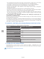
OPERATING CONDITIONS STORAGE AND TRANSPORT
CONDITIONS
MIN MAX MIN MAX
*+10 °C +60°C -30 °C +70 °C
10 % 100% 20 % 70 %
600 mbar 1200 mbar 600 mbar 1200 mbar
It’s very important to assure access to this device only for qualified person – possibility of
misuse.
3.1. OPERATIONAL SAFETY
The panel described in this manual is for cylinder gases and the following general practices are
our recommendations for the safe, ecient storage and use of such compressed gases.
3.1.1. CYLINDER STORAGE
Storage area shall be designed according to valid standard, here are some recommendations:
• Well ventilated with weather protection.
• Free from fire risk. Keep away from sources of heat and ignition. Designated as a ‘no smoking’
area. Clearly marked as a gas store with appropriate hazard warning signs (e.g. flammable,
toxic, etc.).
• Kept clear with access restricted to authorised personnel.
• Provided with appropriate safety/emergency equipment (e.g. Fire extinguisher, breathing
apparatus etc.)

4/164
EN
Compressed gas cylinders (in storage) should be;
• Standing upright where designed for this.
• Properly secured to prevent overturning.
• Fitted with valve protection devices (e.g. caps, guards etc.) where supplied.
• Segregated in the storage area according to the various categories (e.g. flammable, oxidant
etc.).
• Segregated in the storage area according to content and clearly designated full or empty.
• Managed to ensure that the oldest stock is used first.
• Checked periodically for general condition.
Personnel: (who enter the storage area) should be;
• Responsible and competent to maintain the gas store and its contents as above.
• Familiar with and able to identify the contents of the gas containers and their potential hazards.
3.1.2. EMERGENCY PROCEDURES:
An emergency results from:
• A fire near or in the cylinder manifold room.
• An unintended leak of gas from the cylinders or pipeline.
• Some other potential or actual incident which will aect the integrity of the manifold installation.
Procedure to follow:
• Raise the alarm and notify a supervisor and/or call the fire brigade.
• Evacuate all personnel from the immediate danger area.
In case of fire, remove all cylinders:
• Close the cylinder valve(s) on all cylinder(s)/ cylinder bundles.
• Close the bank isolating valve(s).
• Disconnect the high pressure hoses.
• Move the cylinders to a safe area using a suitable cylinder trolley.
In the case of an uncontrollable escape of gas:
• Open the doors to the manifold room to ventilate the area.
• Do not introduce sources of ignition into the area.
It is important that ready access to these instructions is given at all times and that the mani-
fold is not put into operation until the operator is fully familiar with its functions, controls and
safety precautions.
It is the duty of all employers to provide such information, training and supervision according
to national standards as is necessary to ensure so far as is reasonably practical the health and
safety at work of its employees.
4. PERSONNEL INSTRUCTIONS
The Medical Devices Directive 93/42/EEC states that the product provider must ensure that
all personnel handling the product are provided with the operating instructions & performance
data.
Do not use the product without properly familiarization of the product and its safe operation
as defined in this Instruction for use. Ensure user is aware of particular information and knowl-
edge required for the gas in use.
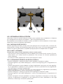
5. PRODUCT DESCRIPTION
The manifolds covered by these instructions are designed to allow equal numbers of cylinders
to be manifold together to give an operating bank and a reserve bank. The operating bank will
deliver gas to the manifold pressure regulator until the cylinders are exhausted. At that point the
supply will switch to the reserve bank and the exhausted bank can be replenished. The object
is to give uninterrupted gas supply.

5/164
EN
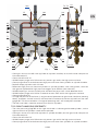
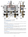
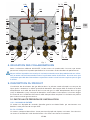
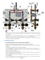
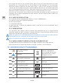
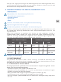
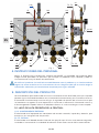
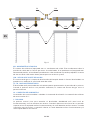
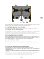
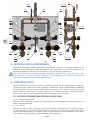
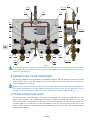
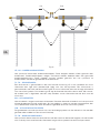
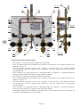
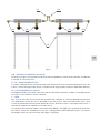
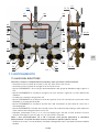
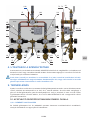
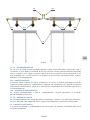
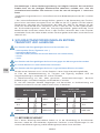
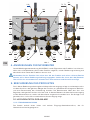
5.1. HIGH PRESSURE SIDE OF THE MANIFOLD:
I1, I2 INLET CONNECTIONS
The manifold contains left and right side threaded inlet connection that fits to the high pressure
hoses.
F1, F2 FILTERS
The manifold contains two high pressure filters which are installed on the inlets of the manifold.
These filters can be easily maintained. Filters include antishock valves that prevent a backflow.
Antishock vlaves are not leaktight.
V1, V2 INLET SHUT OFF VALVES
The manifold contains two inlet shut o valves that are used to open and close the main high
pressure on the left and right side of the manifold unit. By these two valves you can close gas
supply to the hospital pipeline.
V3, V4 PURGE VALVES
The manifold contains two purge valves. Through the purge valves is ventilated high pressure
collecting pipelines on the empty side before removing high pressure hoses from the cylinders.
Also purge valves are used for cleaning of collecting pipeline before opening inlet shut o valve
and supply gas to the main pipeline. Outlet of purge valve has a threaded connection.
R1, R2 REGULATORS
The manifold consists of two high pressure manifold regulators. The regulators reduce the
pressure from cylinder pressure to the outlet pressure setting on manifold outlet. Information
about setting of product you can find in testing report included to the product.
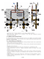
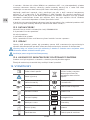
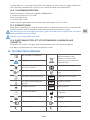
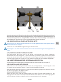
O1
T3, T4
S1, S2
V5
R1
T1
M1
V3 V1
M3 V6
R2
M2
T2
V2 V4
T5
L
T6
P1, P2
F1
I1
E1
V10
F2
I2
Fig. 1

6/164
EN
M1, M2 INLET GAUGES
Each regulator R1 and R2 is equipped with high pressure gauge. These gauges show pressure
in the left and right collecting pipelines. If the product is equipped with contact gauges then
these gauges send information about pressure to the alarm system.
T1, T2 PRESSURE SENSORS
Pressure sensor is installed in each pressure regulator. Main function is to check a leakage on
reserve side and sends information to the alarm. When leakage on reserve side is detected by
pressure drop then alarm starts inform the technical personal. Variant with the transmitters send
information about pressure to the alarm unit.
5.2. LOW PRESSURE SIDE OF THE MANIFOLD:
S1, S2 SAFETY VALVES
The manifold contains two safety valves on each side. When the outlet pressure increase up to
pre-set limit, the safety valve activates and gas is purged out. According to the version can be
equipped with safety valves with manual drain.
P1, P2 PLUGS FOR SERVICING PURPOSES
Instead of these plugs (G1/4”) an external low pressure gauge or other device can be used to
check the manifold parameters, such as outlet pressure or closing pressure.
E1 PURGE PIPE FROM SAFETY VALVES
Purge pipe from safety valves have external dimension 10 mm. The purge pipe must go outside
of the manifold room as is described in installation standard.
V5, V6 SERVICE VALVES
The manifold contains two service valves. These valves are only used for the service. It is not
allowed to operate the service valve with exception of trained service technician. Using these
valves is possible to service the manifold without interruption of the gas supply.
T3, T4 PRESSURE SENSORS
Pressure sensor installed in the outlet block to the slot with marking LP sends information to
the alarm about empty of supplying side. Pressure sensor installed in the slot with marking HP
sends information to the alarm about too high outlet pressure. Variant with pressure transmitter
has only one sensor and other side is sealed only by a plug. Transmitters send information
about pressure to the alarm unit.
M3 OUTLET GAUGE
Outlet block is equipped with outlet gauge. The gauge shows outlet pressure of the manifold
that is supplied to the stabilizer. If the product is equipped with contact gauge then the gauge
sends information about preset pressure to alarm system.
V10 OUTLET SHUT OFF VALVES
Gas supply to the hospital pipeline system from the manifold unit is possible to close by outlet
shut o valve.
T5, T6 MICRO SWITCHES
The manifold contains two micro switches that control the lever position. When the lever is in an
incorrect position Gas Alarm informs the technical personnel.
O1 OUTLET CONNECTION
Outlet connecting must be soldered to the pipeline. Outlet connection is equipped with male
thread G1/2.
L LEVER
Manual lever is control part of the manifold that makes it possible to decide which side is an
operational and which side is a reserve one. When the manual lever is in upper position left side
is the operational and right side is as the reserve. When the manual lever is in lower position
right side is the operational and left side is as the reserve. The MM40 semiautomatic medical
manifold can be delivered with HP accessories. The accessories contain parts for connecting
gas cylinders. Basic parts of accessories are in picture bellow.

7/164
EN
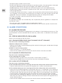
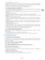
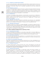
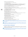
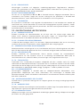
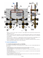
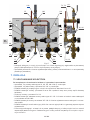
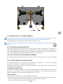
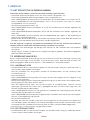
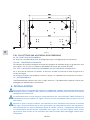
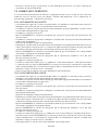
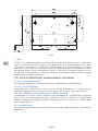
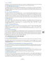
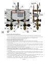
5.2.1. GAS MANIFOLD HIGH PRESSURE ACCESSORIES
P3, P4 CONNECTION POINTS
The accessories contains two connecting points for connecting to the pipelines.
P11, P12 COLLECTING PIPES
Collecting pipes are used for connecting gas cylinders to the manifold. Two equal parts one left
and one right of these pipes should be included to the HP unit.
V13, V14 INLET SHUT OFF VALVES ON COLLECTING PIPES
If collecting pipes are used, inlet shut o valves and antishock valves shall be included. Shut o
valves stops the gas supply between each cylinder and the collecting pipes. Antishock valves
prevent a back flow, they are not leaktight.
H1 CYLINDERS HOLDERS
The accessories can contain cylinders holders. Cylinder holders are used for prevention of the
gas cylinders from falling over.
6. INSTALLATION
It is necessary that an installer of the product is trained and has an appropriate licence ac-
cording to national standards. It is outside the scope of these operating instructions to give
detailed guidance on installations.
The installation must conform to the standard MEDICAL GAS PIPELINE SYSTEMS EN ISO
7396-1 as amended. All tests according this standard have to be fulfilled.
P12P11
P3 V13 P4
H1
V14
Fig. 2

8/164
EN
When working with medical gases it is essential that no oil or grease come into contact with
the gas. This means that hands, tools and work clothes be free from oil or grease before any
work is undertaken. Components used for service must be gas compatible. For oxygen ser-
vice must also be degreased and although they will reach you in this condition care must be
taken during storage and handling.
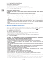
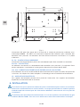
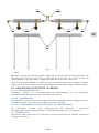
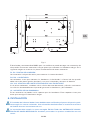
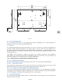
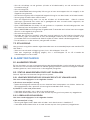
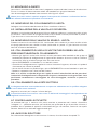
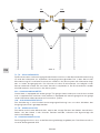
6.1. WALL FIXING
Positioning of the manifold, please consult with responsible central gas system designer. Mount
the manifold at the height to suit either cylinders or cylinder bundles.
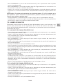
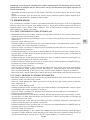
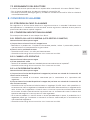
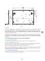
The holes to use for mounting the manifold are shown in Fig. 3.
Be aware that only upper screw is holding the entire weight of the manifold. Size of used
screws shall conform to total load.
6.2. FITTING OUTLET CONNECTION
Solder diameter pipe 15 mm.
6.3. FITTING SAFETY VALVE
Solder diameter pipe 10 mm. The pipes from safety valve and purge valves can (by use of a
T-coupling) be soldered together and have a common outlet outside the manifold room.
6.4. PURGE VALVES OUTLET
Outlet thread W21,8 x 1/14 male. The pipes from safety valve and purge valves can (by use of a
T-coupling) be soldered together and have a common outlet outside the building.
6.5. FITTING TAILPIPES / HIGH PRESSURE HOSES / COLLECTING
BRANCH
• Screw tailpipes / high pressure hoses from cylinders or cylinder bundles / collecting branch
together and then onto the inlet connections on the manifold. Ensure that the shut-o valves
V1 & V2 and the purge valves V3 & V4 are in closed position.
• Open one cylinder from one bank SLOWLY.
Fig. 3

9/164
EN
• Check connection between tailpipe and inlet connection for leakage using a leak detection
fluid.
• If no leakage is detected, open remaining cylinders slowly from that bank. Repeat operation
on opposite bank.
Note: if leakage occurs between tailpipe/high pressure hose/collecting branch and inlet
connection check to see if sealing’s or washers are fitted correctly or missing. If it is damaged
change the sealing and try again.
6.6. FITTING TO SOURCE OF ELECTRICITY
Any work with electric wiring must be carried out by a trained person with an appropriate
licence according to national standards.
Act upon instruction for use for gas alarm.
The product must be grounded through the anchor bolt at the protective earth label.
6.7. CHECKING OF GAS LABEL
The gas label shall be placed on the cover and on the back plate. Check in Appendix Nr. 1 -
Technical data, what type of gas can be used for this product. If a wrong gas label has been
placed on the product it is necessary to exchange it for the correct one. Optional gas labels are
part of the delivery.
6.8. STARTING UP THE MANIFOLD
Detailed description how to start up the manifold can be found in chapter 7.1.
6.9. REGULATORS SETTINGS
Setting of the manifold is in the Testing report - see appendix Nr. 1. You can set dierent
parameters - see below mentioned description.
When the manifold is completely installed the outlet pressure shall be checked. You can change
outlet pressure from regulators.
SETTING CONDITION:
Set left and right regulators with full cylinders or cylinder bundles. Inlet pressure of left and
right manifold side should be the same. Inlet pressure should be min. 180 bar and flow equal
to 8 m3/h.
SETTING LIMITS
Set left and right side for same outlet pressure:
• max. outlet pressure for operating side is 12 bar. (Pressure sensor T3 marked LP must be set 1
bar below the outlet pressure of operating side.)
• min. outlet pressure for reserve side is 7 bar.
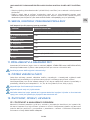
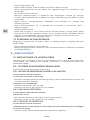
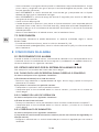
SETTING PRESSURE ON REGULATORS
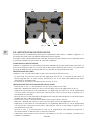
• Place lever L into the left position (lever is pointing up).
• Loose thread B to loosen the lever L from the clamp of control screws of the regulators C1 &
C2.
• Set required outlet pressure on left regulator using control regulator screw C1 (tighten eect
upper pressure, loosen efect lower pressure) and observing the outlet gauge M3.
• Tighten lever L to clamp of control screw of regulators in the original position, micro switch T6
have to be switched on in this position.
• Place lever L into the right position (lever is pointing down).
• Loose thread B to loosen the lever L from the clamp of control screws of the regulators C1 &
C2.
• Set required outlet pressure on left regulator using control regulator screw C2 (tighten eect
upper pressure, loosen eect lower pressure) and observing the outlet gauge M3.
• Tighten lever L to clamp of control screw of regulators in the original position, micro switch T5
have to be switched on in this position.
• Check again outlet pressure for left and right side of manifold, if is necessary repeat setting
procedure.

10/164
EN
7. OPERATION
7.1. START UP OF MANIFOLD
When the manifold is completely installed and the parameters are checked.
• Check that shut o valves V1 & V2, V5 & V6 and V10 are closed.
• Check that both purge valves V3 & V4 are closed.
• SLOWLY open gas flow from cylinders or cylinder bundles into the inlets I1 & I2.
• SLOWLY open purge valves V3 & V4 and purge left and right inlet part of the manifold.
• Close purge valves V3 & V4.
• SLOWLY open inlet shut o valves V1 & V2. The cylinder pressures can be read on the gauges
M1 & M2.
• SLOWLY open service valves V5 & V6. The outlet pressure can be read on the gauge M3.
• SLOWLY open outlet shut o valve V10. The gas supply will start flowing into the pipeline
through outlet connection O1.
• Decide by moving the lever L, if right or left bank of cylinders should start to supply. Always
start supply from the bank that has the lowest pressure.
Info: Two micro switches T5 & T6 are fitted to the back plate to electrically decide which side
is monitored for leaking reserve.
• Check all connections for leakage using a leak detection fluid.
• While gas is flowing the pressure in the operating side will fall. This will be indicated on the
inlet gauges M1 or M2.
7.2. BANK CHANGE OVER
At a predetermined pressure set of the manifold regulators of 10,5 bar, the reserve bank will
take over from the near empty bank of cylinders. You will have an alarm “Change of operating
side”. It is indicated by pressure switches. (See Chapter 8 – Alarm conditions).
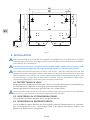
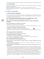
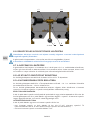
7.2.1. LEFT HAND LH SIDE EMPTY
• The inlet pressure gauge M1 on the left-hand side is indicating exhausted cylinders, so the
left-hand bank of cylinders needs to be replaced.
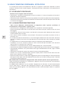
C2C1
BL
Fig. 4

11/164
EN
• Close gas source shut o valve (cylinder or cylinder bundles) on the left hand side prior to
inlet connection I1.
• Close shut-o valve V1.
• SLOWLY open purge valve V3 to vent any excess gas within the high pressure hose.
• Close purge valve V3 and disconnect high pressure hose from cylinders or cylinder bundles.
• Replace empty cylinders with full ones.
• Reconnect high pressure hose to cylinders or cylinder bundles. Use new gaskets, lubricate
with grease approved for high pressure oxygen up to 250 bar (like lubricant).
• SLOWLY open gas source shut o valve and leak test joints with a leak detection fluid.
• SLOWLY open purge valve V3 for 5 seconds to vent “AIR” within the high pressure hose.
• Close purge valve V3.
• Change the position of the lever L, to give normal operation to right-hand side (lever pointing
down), and open shut o valve V1 and read the full content of the new cylinders on the inlet
gauge M1. The alarm condition “Change of operating side” will hereby be cancelled.
• The left hand side is now the reserve bank with full cylinders.
7.2.2. RIGHT HAND RH SIDE EMPTY
• The inlet pressure gauge M2 on the right-hand side is indicating exhausted cylinders, so the
right-hand bank of cylinders needs to be replaced.
• Close gas source shut o valve (cylinder or cylinder bundles) on the right hand side prior to
inlet connection I2.
• Close shut o valve V2.
• SLOWLY open purge valve V4 to vent any excess gas within the high pressure hose.
• Close purge valve V4 and disconnect high pressure hose from cylinders or cylinder bundles.
O1
T3, T4
S1, S2
V5
R1
T1
M1
V3 V1
M3 V6
R2
M2
T2
V2 V4
T5
L
T6
P1, P2
F1
I1
E1
V10
F2
I2
Fig. 1

12/164
EN
• Re-place empty cylinders with full ones.
• Re-connect high pressure hose to cylinders or cylinder bundles. Use new gaskets, lubricated
with grease approved for high pressure oxygen up to 250bar (like lubricant).
• SLOWLY open gas source shut-o valve and leak test joints with a leak detection fluid.
• SLOWLY open purge valve V4 for 5 seconds to vent “AIR” within the high pressure hose.
• Close purge valve V4.
• Change the position of the lever L, to give normal operation to left-hand side (lever pointing
up), and open shut-o valve V2 and read the full content of the new cylinders on the inlet
gauge M2. The alarm condition “Change of operating side” will hereby be cancelled.
• The right hand side is now the reserve bank with full cylinders.
7.3. SHUT DOWN
It is possible shut down the manifold only with responsible person agreement in compliance
with EN ISO 7396-1.
• For short term (hours) shutdown close shut-o valves V1 & V2.
• For long term (days) shutdown close shut-o valves V1 & V2 and the cylinder shut-o valves.
8. ALARM CONDITIONS
8.1. ALARM PROCEDURE
On signal of alarm condition the appropriate visual indicator is illuminated on the alarm unit. The
alarm condition shall be recorded and the necessary action taken, as detailed in the sections
below.
8.2. STATUS INDICATED BY GAS ALARM
Always use instruction for the Gas Alarm.
8.2.1. LEAKING RESERVE SIDE RIGHT LEAKAGE OR LEFT LEAKAGE
The alarm starts in following situations:
a) Reserve side pressure is too low
• Allocate the leakage using leak detecting fluid. Isolate the leaking area and do repair/change
component or washer.
b) Lever L is not in correct position
• Check if the lever L is in correct position.
• Check that the audible and visual alarms on the Gas Alarm have been cancelled.
8.2.2.CHANGE OF OPERATING SIDE
The alarm starts in following situations:
a) The supplying side is empty
• Replace the empty cylinders with full cylinders as described in chapter 7.
• Check that the audible and visual alarms on the alarm have been cancelled.
8.2.3. HIGH OUTLET PRESSURE
The alarm starts in following situations:
a) The manifold outlet pressure is too high (version with safety valves without manual drain)
• Contact authorised service to replace the regulator with a new or refurbished one.
b) The manifold outlet pressure is too high (version with safety valves with manual drain)
• Check that the manifold regulator R1 & R2 outlet pressure is as preferred. If not, isolate the
regulator by closing valve V5 or V6 and check one regulator at a time. Start with the regulator
on reserve side, relief the pressure by the safety valve S1 & S2 and check if the pressure
increases again. Change operating side and make the same test with the other regulator.
• If you shortly after resetting the regulator have the same alarm condition again, the regulator
most likely has internal leakage. Contact authorised service for replace the regulator with a
new or refurbished unit.
• Check that the audible and visual alarms on the Gas Alarm have been cancelled.

13/164
EN
9. ROUTINE MAINTENANCE INSTRUCTION
Routine maintenance shall be carried out only by authorized person according to national
standards. Use only original GCE components. Contact GCE for further information about repair
procedures.
9.1. THE FOLLOWING ROUTINE CHECKS
- should be made on a weekly basis:
• Check all valves for correct operation and leak test using a laek detection fluid.
• Check pipe work for leaks using a leak detection fluid.
• Check that all notices are in place, can be easily read and are not obstructed from view.
• Inspect the vicinity of cylinders for anything introduced since last inspection, which could
aect the continuing safe operation of the manifold.
9.2. GENERAL MAINTENANCE
- should be undertaken in accordance with a planned maintenance schedule, which should
include the following items:
• Leak test all connections using a leak detection fluid.
• High pressure hoses should receive particular attention to ensure they are secure, not worn
or otherwise weakened.
• Components with limited lifetimes, such as high pressure hoses, should be subjected to a
routine replacement programme.
• Filters are in good condition and not blocked. Filter elements may need to be cleaned or
renewed and pipelines may need to be blown through to remove foreign material.
• Valves to be used in normal or emergency operation are accessible and easy to operate.
Valves at service point’s outlets and purge valves should be checked for gas tightness.
• The setting and operation of regulators is satisfactory.
• The necessary safety devices and instruments are fitted, are of the correct type and do not
show signs of deterioration or not authorized interference.
• The equipment downstream of the outlet point is suitable for further service.
• Check connecting nuts and seating faces are undamaged.
• Check gauges operate smoothly and zero correctly.
• Check isolating valves for closure tightness and gland leakage.
• The gas manifold room must always remain thoroughly clean. Materials other than those
required for operating the manifold must not be stored in the room.
• Replace all worn or damaged parts with original spare parts. Remember that gaskets, o-rings
and sealing surfaces must be clean and free from damage to work eectively.
Safety note-as part of the planned maintenance special checks should be made to ensure:
All changes (including removal and addition of parts) and extensions conform to the right code
of practice.
Changes in the vicinity of the installation do not aect the safety of the operation e.g. proximity
of electricity to fuel gases, oils and combustibles near to oxygen, illicit use of a pipeline as an
electrical conductor or as a support for other items.

14/164
EN
10. SCHEME OF EXAMINATION
GCE recommendations for a Written Scheme of Examination:
EQUIPMENT EXAMINATION INTERVAL
1. High pressure hoses Examine when changing cylinders. Replace every 5 years
2. Pipe connections 1 year
3. Safety Relief Valve 1 year
4. Regulator 1 year
5. Non Return Valves 1 year
6. Valves 1 year
7. Alarm system Check when changing cylinders.
8. Filters 1 year
11. ACCESSORIES AND SPARE PARTS
Standard accessories are alarm and stabilizer (MM40 - STABILIZER or LINE REGULATOR).
Contact supplier of the system or GCE dealer for spare part lists. Use only GCE original spare
parts.
Use only GCE original spare parts!
12. CLEANING OF EXTERNAL PARTS
Remove dirt with a soft cloth damped in oil free oxygen compatible soap water and rinse with
clean water. If other cleaning solutions are used, check that they are not abrasive and that they
are compatible with: Cu, Fe, Al alloy, brass, plastic materials of components, labels and gas.
Do not use cleaning solutions containing ammonia!
Do not immerse in water or any liquid.
Do not clean electrical connections when the power is on. Make sure the connections are dry
before turning power back on.
13. LIFETIME, REPAIR AND DISPOSAL
13.1. LIFE TIME AND WASTE MANAGEMENT
The maximum life time of the product is 10 years at compliance of Examination schedule
(chapter 10). At the end of the product’s life time, the product must be withdrawn from service.
The owner of the device shall prevent the reuse of the product and handle the product in
compliance with “Directive of European Parliament and Council 2008/98/EC on waste“.
In accordance to Article 33 of REACH GCE, s.r.o. as responsible manufacturer shall inform all
customers if materials containing 0.1% or more of substances included in the list of Substance
of Very High Concern (SVHC).
The most commonly used brass alloys used for bodies and other brass components contain
2-3% of lead (Pb), EC no. 231-468-6, CAS no. 7439-92-1. The lead will not be released to the gas
or surrounding environment during normal use. After end of life the product shall be scrapped
by an authorized metal recycler to ensure ecient material handling with minimal impact to
environment and health.

15/164
EN
To date we have no information that indicates that other materials containing SVHC of
concentrations exceeding 0.1% are included in any GCE product.
13.2. MANUFACTURING DATE
The manufacturing date is included in product serial number which is marked on back plate.
Serial number composition is the following: YYMMXXXXX
Y: 2 last numbers of the year of manufacture
M: month of manufacture
X: production number
The perforation in the device label indicates the year when the equipment has to be disposed
o.
13.3. REPAIR
Repair activities of GCE product must be carried out by GCE or authorized repair centers.
Contact GCE for further information about service available in your area.
All labels on the equipment must be kept in good, legible condition by the owner and the
user during the entire product life time.
Use only genuine GCE components.
13.4. DISPOSAL AT THE END OF THE PRODUCT’S LIFE TIME
Product must be recycled in compliance with the national and local regulations.
No part contains any chemical materials burdensome environment.
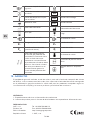
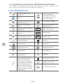
14. GLOSSARY
Consult instruction for use Take back equipment for
recycling. Do not dispose
equipment into unsorted
municipal waste
Caution!
Keep away from heat and
flammable materials Suitable for Hospital care use
Keep away from oil and
grease!
Take back battery
for recycling
Humidity limit SN Serial number
Temperature limit REF Catalogue number
Keep dry! LOT Batch code
Date of manufacture Manufacturer
Use by date Fragile, handle with care
Inlet parameter Outlet parameter

16/164
EN
P1Inlet pressure range P2Outlet pressure
P4
Max outlet pressure (closing
pressure) QOutlet flow
Service or disposal date The
serial number indicates the
year product has to undergo
the overall maintenance ac-
tivities or has to be disposed
o. Refer to the serial number
note to determine the Overall
maintenance or disposal.
Weight of product
Atmospheric pressure limit
The protective earth label
15. WARRANTY
The Standard Warranty period is two years from date of receipt by the GCE Customer (or if this
is not known 2 years from time of the product manufacture shown on the product).
The standard warranty is only valid for products handled according to Instruction for use (IFU)
and general industry good practice and standards.
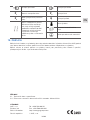
APPENDIX:
Nr 1 - Technical specification and performance data
Nr 2 - Testing report for relevant number of reduction unit– Serial Number
MANUFACTURER:
GCE, s.r.o. Tel: +420 569 661 111
Zizkova 381 Fax: +420 569 661 602
583 01 Chotebor http://www.gcegroup.com
Czech Republic © GCE, s.r.o.

17/164
CS
1. PŘEDMLUVA
Tento návod k použití poskytuje nezbytné informace pro celý životní cyklus výrobku:
• instalace,
• provoz a změna provozních stran,
• alarmové podmínky,
• údržba a čištění,
• likvidace.
GCE medicinální rozvodové systémy jsou zdravotnickými prostředky klasifikovanými ve třídě IIb
dle Medicinální Direktivy 93/42/EHS.
Splnění základních požadavků Medicinální Direktivy 93/42/EHS je založeno na výrobních
normách EN ISO 7396-1 a EN 60601-1.
2. ÚČEL POUŽITÍ
Poloautomatická medicinální redukční stanice MM40-HP UNIT je určena k použití v rozvodových
systémech nemocnic jako zdroj medicinálního plynu a jednotka pro redukci tlaku plynu.
Společně s redukční medicinální stanicí musí být vždy použit signalizační zařízení (Gas Alarm),
které je v souladu s normami EN ISO 7396-1 a EN 60601-1. Společně se stanicí MM40-HP UNIT
může být použit také medicinální stabilizér (LINE REGULATOR nebo MM40-STABILIZER) pro
snížení tlaku, který je distribuován do distribučního systému nemocnice. Medicinální stabilizér
musí být instalován v souladu s normami EN ISO 7396-1 a EN 60601-1. Pro více informací o
příslušenství (Gas Alarm nebo Stabilizer) čtěte návod k použití pro daný produkt.
Tento návod k použití detailně popisuje provozní a bezpečnostní postup pro použití stanice
MM40-HP UNIT. Medicinální rozvodová stanice je k dispozici pro kyslík, oxid dusný*, a stlačený
vzduch, může být také použita pro oxid uhličitý*, dusík a směs plynů pro medicinální aplikace.
Tato stanice je navržena pro provoz při maximálním tlaku 200 bar**.
Poznámka: Oxid dusný a Oxid uhličitý jsou kapalné plyny. Tyto plyny se při expanzi extrémně
ochlazují a mohou způsobovat zamrzání redukčního ventilu. Je nutno instalovat ohřívače na
obě strany medicinální redukční stanice (celkem 2 ohřívače na redukční stanici).
Před použitím čtěte návod k použití. Vždy tyto instrukce dodržujte!
Zařízení může být použito pouze pro účel stanovený v tomto návodu k použití!
Zařízení musí být instalováno kvalifikovanou osobou a v souladu s požadavky normy ENISO
7396-1 v posledním znění!
Pro zajištění bezpečnosti pacienta, před použitím zkontrolujte zařízení a příslušenství, zda
jeho data a specifikace odpovídá určenému účelu použití.
Zařízení nesmí být za žádných okolností modifikováno jinou osobou než výrobcem!
Zařízení nesmí být použito pro jiný plyn, než který určený štítkem.
Obrázky v tomto návodu k použití jsou pouze informativní. Skutečný produkt se může lišit dle
dané varianty produktu a / nebo nemusí obsahovat všechny části popsané níže. Vždy čtěte
přílohu č. 1 - technická data.
* Redukční stanice musí být instalována v místnosti s minimální teplotou 10°C.
** Maximální provozní tlak je 200 bar myšleno pro použití s lahvemi naplněnými na maximální
ustálený tlak 200 bar (při 15 °C). Při vyšších teplotách lahvový tlak přesáhne hodnotu 200 bar.
Například lahvový tlak Kyslíku při teplotě 50 °C je 240 bar. Tlak vyznačený na štítcích redukčních
ventilů i redukčních stanicích značí maximální ustálený tlak v lahvích, nikoliv vyvíjený tlak v
lahvích, toto by mělo být shodné s maximálním tlakem označeným na lahvích
ČESKY
NÁVOD K POUŽITÍ: MM40 HP UNIT

18/164
CS
3. BEZPEČNOSTNÍ POŽADAVKY NA PROVOZ, PŘEPRAVU
A SKLADOVÁNÍ
UDRŽUJTE VÝROBEK A JEHO PŘÍSLUŠENSTVÍ MIMO:
• zdroje tepla (oheň, cigarety,...),
• hořlavé materiály,
• oleje a mastnotu (pozor při používání krémů na ruce),
• vody,
• prachu.
Výrobek a jeho příslušenství musí být zajištěny proti pádu.
Vždy dodržujte normy pro čistotu kyslíku.
Výrobek a jeho příslušenství se smí používat pouze v dobře odvětraných prostorech.
Před prvním použitím by měl být produkt ponechán v originálním balení. GCE doporučuje použít
originální obal, pokud je produkt vyřazen z provozu (přeprava, skladování).
Poskytovatel produktu musí zajistit, aby během životního cyklu, transportní a skladovací
podmínky byly v souladu s níže zmíněnými “bezpečnostními předpisy” tak, aby byla zachována
jeho funkčnost a čistota. Je nutné dodržovat lokální právní předpisy, pravidla a předpisy pro
medicinální plyny, pro prevenci nehod a ochranu životního prostředí.
PROVOZNÍ PODMÍNKY SKLADOVACÍ A PŘEPRAVNÍ
PODMÍNKY
MIN MAX MIN MAX
*+10 °C +60°C -30 °C +70 °C
10 % 100% 20 % 70 %
600 mbar 1200 mbar 600 mbar 1200 mbar
Zajistěte stanici proti použití nekompetentí osobou!
3.1. PROVOZNÍ BEZPEČNOST
Stanice popsaná níže v tomto návodu je určena pro použití s tlakovými lahvemi a následující
všeobecné postupy obsahují naše doporučení pro bezpečné a efektivní skladování a použití
stlačených plynů.
3.1.1. SKLADOVÁNÍ TLAKOVÝCH LAHVÍ
Sklad tlakových lahví musí být navržen v souladu s platnou normou, níže naleznete několik
doporučení:
• dobře odvětraný prostor chráněný proti venkovnímu počasí.
• Zajistěte prostor proti nebezpečí požáru. Udržujte mimo tepelné a zápalné zdroje. Označte
prostory značením pro “Zákaz kouření”.
• Viditelně označte jako sklad plynu vhodným bezpečnostním značením (např. hořlaviny,
toxické materiály, atd.)
• Udržujte v čistotě a zajistěte vstup pouze autorizovaným osobám.
• Zajistěte prostory vhodným bezpečnostním zařízením (např. hasicí přístroj, dýchací přístroje,
apod.)
Tlakové lahve (ve skladu) by měly být:
• umístěny ve vzpřímené pozici na místě k tomu určenému,
• zabezpečeny proti převrácení,
• opatřeny ochrannými krytkami ventilů (např. krytky, víka, atd.), kde jsou součástí dodávky,

19/164
CS
• rozděleny ve skladovacím prostoru dle různých typů (např. hořlavé, oxidační, atd.)
• rozděleny v prostoru dle množství obsahu a jasně označeny jako plné nebo prázdné,
• skladovány systémem FIFO (nejstarší zboží se vyskladňuje jako první),
• kontrolovány periodicky (obecný stav).
Obsluha: (kdo vstupuje do skladu) by měla být:
• zodpovědná a kompetentní k údržbě skladu plynových lahví a jejich obsah dle doporučení
výše.
• obeznámena a schopná identifikovat obsahy plynových lahví a svazků a potencionální
nebezpečí dané jejich obsahem.
3.1.2. POHOTOVOSTNÍ POSTUPY:
Stav pohotovosti je důsledkem:
• ohně v rozvodové místnosti nebo v její blízkosti,
• nezamýšleného úniku plynu z lahve nebo potrubí,
• další potencionální nebo aktuální poruchy, která má důsledek na celistvost instalace tlakové
stanice.
Postupujte následovně:
• Spusťte signalizační zařízení a informujte správce a/nebo volejte hasiče.
• Evakuujte všechny osoby z nebezpečného prostoru.
V případě požáru přesuňte plynové lahve:
• zavřete uzavírací ventily na všech lahvích a svazcích,
• zavřete izolační ventily,
• odpojte vysokotlaké hadice,
• přesuňte lahve na bezpečné místo pomocí vhodného vozíku na lahve.
V případě nekontrolovaného úniku plynu:
• otevřete dveře distribuční místnosti pro odvětrání prostor,
• nepoužívete zápalné zdroje v těchto prostorech.
Je důležité zajistit neustálý přístup k tomuto návodu k použití a ubezpečit se, že obsluha je
plně obeznámena s funkcemi, ovládáním a bezpečnostními předpisy před samotnou manipu-
lací se stanicí.
Je povinností všech zaměstnavatelů poskytnout takové informace, školení a dozor, které jsou
v souladu s místními předpisy a zajišťují také maximální možnou ochranu zdraví a bezpečnosti
zaměstnanců při práci.
4. INSTRUKTÁŽ PRACOVNÍKŮ
Dle medicinální direktivy 93/42/EHS má poskytovatel zařízení povinnost poskytnout všem
uživatelům a osobám manipulujícím s výrobkem návod k použití & technickou dokumentaci pro
daný produkt.
Nepoužívejte produkt bez řádného seznámení s výrobkem a jeho bezpečného provozu, jak
je definováno v tomto návodu k použití. Zajistěte, aby si uživatel byl vědom konkrétních infor-
mací a znalostí požadovaných pro používaný plyn.
5. POPIS PRODUKTU
Rozvodové zařízení plynu popsané v tomto návodu k použití je navrženo tak, že připojením
stejného množství lahví na každou stranu zařízení vznikne provozní a rezervní strana dodávky
plynu. Provozní strana zařízení dodává plyn k regulátoru, dokud se lahve nevyprázdní. V té chvíli
se dodávka plynu přepne na rezervní stranu a prázdná strana může být vyměněna. Zařízení je
navrženo tak, aby poskytovalo nepřetržitou dodávku plynu.

20/164
CS
5.1. VYSOKOTLAKÁ ČÁST ZAŘÍZENÍ
I1, I2 VSTUPNÍ PŘIPOJENÍ
Stanice obsahuje levé a pravé závitové vstupní připojení, které je vhodné pro vysokotlaké
hadice.
F1, F2 FILTRY
Stanice obsahuje dva vysokotlaké filtry s nainstalovanými zpětnými vetily, které jsou instalovány
u vstupu rozvodné jednotky. Tyto filtry jsou snadno udržovatelné.
V1, V2 VSTUPNÍ UZAVÍRACÍ VENTILY
Stanice obsahuje dva vstupní uzavírací ventily, které jsou určeny k zavírání a otevírání proudu
vysokého tlaku plynu na levé a pravé straně rozvodové stanice. Těmito dvěma uzavíracími
ventily může být uzavřena distribuce plynu do nemocničního potrubí
V3, V4 ODVZDUŠŇOVACÍ VENTILY
Stanice obsahuje dva odvzdušňovací ventily. Odvzdušňovacími ventily je odpouštěn
tlak v prázdné straně sběrného potrubí před odmontováním vysokotlakých hadic z lahví.
Odvzdušňovací ventily jsou také použity pro čištění sběrného potrubí před otevřením vstupního
uzavíracího ventilu a vpuštěním plynu do hlavního potrubí. Výstup odvzdušňovacího ventilu má
závitový spoj.
R1, R2 REGULÁTORY
Zařízení obsahuje dva vysokotlaké rozvodové regulátory. Regulátory slouží ke snížení vysokého
vstupního tlaku plynu na požadovaný výstupní tlak plynu rozvodné stanice. Informace o
nastavení naleznete v testovacím záznamu přiloženém k produktu.
O1
T3, T4
S1, S2
V5
R1
T1
M1
V3 V1
M3 V6
R2
M2
T2
V2 V4
T5
L
T6
P1, P2
F1
I1
E1
V10
F2
I2
Obr. 1
La pagina si sta caricando...
La pagina si sta caricando...
La pagina si sta caricando...
La pagina si sta caricando...
La pagina si sta caricando...
La pagina si sta caricando...
La pagina si sta caricando...
La pagina si sta caricando...
La pagina si sta caricando...
La pagina si sta caricando...
La pagina si sta caricando...
La pagina si sta caricando...
La pagina si sta caricando...
La pagina si sta caricando...
La pagina si sta caricando...
La pagina si sta caricando...
La pagina si sta caricando...
La pagina si sta caricando...
La pagina si sta caricando...
La pagina si sta caricando...
La pagina si sta caricando...
La pagina si sta caricando...
La pagina si sta caricando...
La pagina si sta caricando...
La pagina si sta caricando...
La pagina si sta caricando...
La pagina si sta caricando...
La pagina si sta caricando...
La pagina si sta caricando...
La pagina si sta caricando...
La pagina si sta caricando...
La pagina si sta caricando...
La pagina si sta caricando...
La pagina si sta caricando...
La pagina si sta caricando...
La pagina si sta caricando...
La pagina si sta caricando...
La pagina si sta caricando...
La pagina si sta caricando...
La pagina si sta caricando...
La pagina si sta caricando...
La pagina si sta caricando...
La pagina si sta caricando...
La pagina si sta caricando...
La pagina si sta caricando...
La pagina si sta caricando...
La pagina si sta caricando...
La pagina si sta caricando...
La pagina si sta caricando...
La pagina si sta caricando...
La pagina si sta caricando...
La pagina si sta caricando...
La pagina si sta caricando...
La pagina si sta caricando...
La pagina si sta caricando...
La pagina si sta caricando...
La pagina si sta caricando...
La pagina si sta caricando...
La pagina si sta caricando...
La pagina si sta caricando...
La pagina si sta caricando...
La pagina si sta caricando...
La pagina si sta caricando...
La pagina si sta caricando...
La pagina si sta caricando...
La pagina si sta caricando...
La pagina si sta caricando...
La pagina si sta caricando...
La pagina si sta caricando...
La pagina si sta caricando...
La pagina si sta caricando...
La pagina si sta caricando...
La pagina si sta caricando...
La pagina si sta caricando...
La pagina si sta caricando...
La pagina si sta caricando...
La pagina si sta caricando...
La pagina si sta caricando...
La pagina si sta caricando...
La pagina si sta caricando...
La pagina si sta caricando...
La pagina si sta caricando...
La pagina si sta caricando...
La pagina si sta caricando...
La pagina si sta caricando...
La pagina si sta caricando...
La pagina si sta caricando...
La pagina si sta caricando...
La pagina si sta caricando...
La pagina si sta caricando...
La pagina si sta caricando...
La pagina si sta caricando...
La pagina si sta caricando...
La pagina si sta caricando...
La pagina si sta caricando...
La pagina si sta caricando...
La pagina si sta caricando...
La pagina si sta caricando...
La pagina si sta caricando...
La pagina si sta caricando...
La pagina si sta caricando...
La pagina si sta caricando...
La pagina si sta caricando...
La pagina si sta caricando...
La pagina si sta caricando...
La pagina si sta caricando...
La pagina si sta caricando...
La pagina si sta caricando...
La pagina si sta caricando...
La pagina si sta caricando...
La pagina si sta caricando...
La pagina si sta caricando...
La pagina si sta caricando...
La pagina si sta caricando...
La pagina si sta caricando...
La pagina si sta caricando...
La pagina si sta caricando...
La pagina si sta caricando...
La pagina si sta caricando...
La pagina si sta caricando...
La pagina si sta caricando...
La pagina si sta caricando...
La pagina si sta caricando...
La pagina si sta caricando...
La pagina si sta caricando...
La pagina si sta caricando...
La pagina si sta caricando...
La pagina si sta caricando...
La pagina si sta caricando...
La pagina si sta caricando...
La pagina si sta caricando...
La pagina si sta caricando...
La pagina si sta caricando...
La pagina si sta caricando...
La pagina si sta caricando...
La pagina si sta caricando...
La pagina si sta caricando...
La pagina si sta caricando...
La pagina si sta caricando...
La pagina si sta caricando...
La pagina si sta caricando...
La pagina si sta caricando...
La pagina si sta caricando...
La pagina si sta caricando...
-
 1
1
-
 2
2
-
 3
3
-
 4
4
-
 5
5
-
 6
6
-
 7
7
-
 8
8
-
 9
9
-
 10
10
-
 11
11
-
 12
12
-
 13
13
-
 14
14
-
 15
15
-
 16
16
-
 17
17
-
 18
18
-
 19
19
-
 20
20
-
 21
21
-
 22
22
-
 23
23
-
 24
24
-
 25
25
-
 26
26
-
 27
27
-
 28
28
-
 29
29
-
 30
30
-
 31
31
-
 32
32
-
 33
33
-
 34
34
-
 35
35
-
 36
36
-
 37
37
-
 38
38
-
 39
39
-
 40
40
-
 41
41
-
 42
42
-
 43
43
-
 44
44
-
 45
45
-
 46
46
-
 47
47
-
 48
48
-
 49
49
-
 50
50
-
 51
51
-
 52
52
-
 53
53
-
 54
54
-
 55
55
-
 56
56
-
 57
57
-
 58
58
-
 59
59
-
 60
60
-
 61
61
-
 62
62
-
 63
63
-
 64
64
-
 65
65
-
 66
66
-
 67
67
-
 68
68
-
 69
69
-
 70
70
-
 71
71
-
 72
72
-
 73
73
-
 74
74
-
 75
75
-
 76
76
-
 77
77
-
 78
78
-
 79
79
-
 80
80
-
 81
81
-
 82
82
-
 83
83
-
 84
84
-
 85
85
-
 86
86
-
 87
87
-
 88
88
-
 89
89
-
 90
90
-
 91
91
-
 92
92
-
 93
93
-
 94
94
-
 95
95
-
 96
96
-
 97
97
-
 98
98
-
 99
99
-
 100
100
-
 101
101
-
 102
102
-
 103
103
-
 104
104
-
 105
105
-
 106
106
-
 107
107
-
 108
108
-
 109
109
-
 110
110
-
 111
111
-
 112
112
-
 113
113
-
 114
114
-
 115
115
-
 116
116
-
 117
117
-
 118
118
-
 119
119
-
 120
120
-
 121
121
-
 122
122
-
 123
123
-
 124
124
-
 125
125
-
 126
126
-
 127
127
-
 128
128
-
 129
129
-
 130
130
-
 131
131
-
 132
132
-
 133
133
-
 134
134
-
 135
135
-
 136
136
-
 137
137
-
 138
138
-
 139
139
-
 140
140
-
 141
141
-
 142
142
-
 143
143
-
 144
144
-
 145
145
-
 146
146
-
 147
147
-
 148
148
-
 149
149
-
 150
150
-
 151
151
-
 152
152
-
 153
153
-
 154
154
-
 155
155
-
 156
156
-
 157
157
-
 158
158
-
 159
159
-
 160
160
-
 161
161
-
 162
162
-
 163
163
-
 164
164


in altre lingue
- français: GCE MM40 Mode d'emploi
- español: GCE MM40 Instrucciones de operación
- Deutsch: GCE MM40 Bedienungsanleitung
- slovenčina: GCE MM40 Návod na používanie
- polski: GCE MM40 Instrukcja obsługi
Documenti correlati
-
GCE PRESSURE WATCH Istruzioni per l'uso
-
-
-
-
-
-
-
Altri documenti
-
Varian Saturn 2000 GC/MS Manuale utente
-
Miller TRAILBLAZER 2G Manuale del proprietario
-
-
 Unical KMPS HI - Pavimento/Parete Guida d'installazione
-
-
Regal 42 Fly-Grande Coupe Manuale del proprietario
-
-
 Unical CS10 - Cassette Guida d'installazione
-
 Unical XMX HE / KMX HE - Unità Esterne Guida d'installazione
-
 Unical CS10 - Cassette Guida d'installazione


