
IT
Italiano
EN
English
FR
Français
RU
Pусский
Bordo sensibile di sicurezza
DFWN1500 / 1700 / 2000 / 2500
DFWN1500N / 1700N / 2000N / 2500N
MANUALE DI INSTALLAZIONE
FA01753M04

L
190
46
101
RV118I
RV118A
RV118N
RV118M
TMFW - TMFWN
TMF6W - TMF6WN
RV117H
Pag. 22 - Codice manuale FA 01753- ITFA01753- IT - 01/2022 - © Came S.p.A. - I contenuti del manuale sono da ritenersi suscettibili di modifica in qualsiasi momento senza obbligo di preavviso
IMPORTANTI ISTRUZIONI DI SICUREZZA PER L’INSTALLAZIONE
ATTENZIONE! L’INSTALLAZIONE NON CORRETTA PUÓ CAUSARE GRAVI DANNI, SEGUIRE TUTTE LE ISTRUZIONI DI INSTALLAZIONE
IL PRESENTE MANUALE È DESTINATO ESCLUSIVAMENTE A INSTALLATORI PROFESSIONALI O A PERSONE COMPETENTI
LEGENDA
Parti da leggere con attenzione.
⚠ Parti riguardanti la sicurezza.
☞ Cosa comunicare all’utente.
RIFERIMENTI NORMATIVI
Il prodotto è conforme alle direttive di riferimento vigenti.
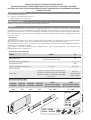
DESCRIZIONE
Questo prodotto è progettato e costruito da Came S.p.A. in conformità alle vigenti norme di sicurezza, ed è certificato
(PR&S n.04.363) per applicazione in verticale e orizzontali.
Il bordo sensibile è costituito da un profilo di supporto in alluminio e da un profilo e due tappi in gomma. All’interno del profilo
in gomma ci sono due meccanismi a leve snodate unite da una fune in acciaio (ø 1,3 mm).
Destinazione d'uso
Il bordo sensibile di sicurezza è destinato alla protezione dal rischio di schiacciamento e di intrappolamento. La rilevazione
avviene per contatto su tutta la lunghezza del bordo, compresi i tappi.
Ogni installazione e uso difformi da quanto indicato nel seguente manuale sono da considerarsi vietate.
⚠ Il presente manuale è destinato solamente al personale tecnico professionale o persona qualificata per l’installazione.
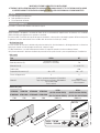
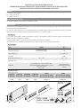
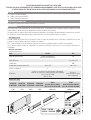
Dati tecnici
Tipo DFWN DFI
Grado di protezione (IP) 54 (fissato in verticale)
44 (fissato in orizzontale) 56
Alimentazione (V) - 12-24 AC / DC
Fusibile (mA) - 630
Temperatura di esercizio (°C) -20 ÷ +55 -20 ÷ +55
Classe dell'apparecchio II II
Materiali
Profilo in gomma termoplastico CCA 48SHA
Tappi in gomma termoplastico SEBS 60SHA
Leve snodate POM
Fune in acciaio
Scatola in
tecnopolimero isolante
autoestinguente
Dimensioni (mm)
DFWN1500
DFWN1500N
DFWN1700
DFWN1700N
DFWN2000
DFWN2000N
DFWN2500
DFWN2500N
DFWN
(RV117H+RV118I+TMFW)
(RV117H+RV118N+TMFWN)
DFWN
(RV117H+RV118A+TMF6W)
(RV117H+RV118M+TMF6WN)
1500 1700 2000 2500 4000 max 6000 max

DFWN
A
806TF-0060
(RX)
C
DFI
D
D
RIOED8WS
RIOED8WS
RIOCT8WS
DFWN
DFWN
DFWN
DFWN
B
D
806TF-0060
(TX)
C
Pag. 33 - Codice manuale FA 01753- ITFA01753- IT - 01/2022 - © Came S.p.A. -I contenuti del manuale sono da ritenersi suscettibili di modifica in qualsiasi momento senza obbligo di preavviso
Impianto tipo
Collegamento Tipo cavo Sezione cavo
A C - NC
FROR CEI 20-22
CEI EN 50267-2-1
2 X 0,5 mm2
B C - NO - NC 3 X 0,5 mm2
C C - NC Alimentazione 12/24
V
4 X 0,5 mm2
D C - NC (Resistiva 8,2 KOhm) 2 X 0,5 mm2
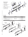
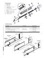
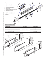
Componenti principali
1. Tappi in gomma
2. Profilo in gomma
3. Fune in acciaio
4. Meccanismo di aggancio fune
5. Profilo in alluminio
6. Staffa di fissaggio
7. Meccanismo portamicro
8. Micro
9. Morsetto per il collegamento elettrico
10. Viti UNI6954 Ø 2,9x13
11. Viti UNI6954 Ø 3,9x13
12. Morsetto di fissaggio

LP
LG
12
140
LOCK
UNLOCK
CAME
CAME
L N
L N
CAME
LN
LN - 30
30
4
3
5
150
4
3
5
150
ⒷⒶ
Pag. 44 - Codice manuale FA 01753- ITFA01753- IT - 01/2022 - © Came S.p.A. - I contenuti del manuale sono da ritenersi suscettibili di modifica in qualsiasi momento senza obbligo di preavviso
INSTALLAZIONE
⚠ Prima di procedere all’installazione è necessario verificare che il punto di fissaggio del bordo sensibile sia su una superficie
idonea.
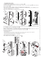
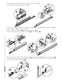
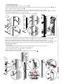
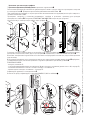
Preparazione del bordo sensibile
Per bordi sensibili di lunghezza non standard, determinare la lunghezza nominale (LN) della zona da proteggere.
Attenzione! Nelle installazioni verticali, ridurre di 30 mm la lunghezza nominale (LN) per evitare il contatto con il suolo.
Forare il profilo con una punta di Ø 3 mm su entrambi i lati per il fissaggio dei tappi .
Inserire il meccanismo di aggancio fune nel profilo dalla parte segnata e fissarlo con le due viti UNI6955 Ø 3,9x13 .
Tagliare il profilo in gomma LG = LN - 285 mm .
⚠ I prodotti DFWN1500/1700/2000/2500 hanno un restringimento sui profili in alluminio Ⓐ. Per quelli da assemblare,
segnare il profilo di alluminio, aiutandosi con una beccanella, a 140 mm dall'estremità Ⓑ.
Tagliare il profilo di alluminio dalla parte opposta del punto segnato LP = LN - 40 mm .

8
9
10
7
6
11
12
13
14
17
15 16
Pag. 55 - Codice manuale FA 01753- ITFA01753- IT - 01/2022 - © Came S.p.A. -I contenuti del manuale sono da ritenersi suscettibili di modifica in qualsiasi momento senza obbligo di preavviso
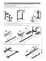
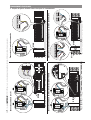
Inserire il profilo in gomma nel profilo in alluminio fino alla battuta del meccanismo .
Infilare la fune in acciaio nel foro superiore del profilo in gomma .
Sbloccare la leva del meccanismo portamicro con una leggera pressione verso il basso , inserire il meccanismo nel profilo
e fissarlo con le due viti UNI6955 Ø 3,9x13 .
Infilare la fune in acciaio nel foro del morsetto 11 e inserire il morsetto nella leva 12.
Mettere in tensione la fune e avvitare il grano del morsetto 13Tagliare la parte di fune in eccedenza 14.
Inserire il tappo dalla parte del meccanismo di aggancio fune 15 e fissarlo con rondelle e viti UNI 6954 ø 3,9 x 13 16.
Nelle applicazioni verticali, per evitare che si formi condensa all’interno del bordo sensibile, forare con punta Ø 4 mm le
tracce presenti sul tappo, prima di montarlo 17.

2
13
Ø 2,5
5
4
6
7
Ø 2,5
5
4
6
7
1
2
3
4
10
11
20 mm
8
9
Pag. 66 - Codice manuale FA 01753- ITFA01753- IT - 01/2022 - © Came S.p.A. - I contenuti del manuale sono da ritenersi suscettibili di modifica in qualsiasi momento senza obbligo di preavviso
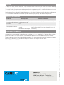
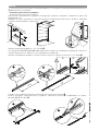
Fissaggio del bordo sensibile
Predisporre un tubo corrugato (Ø 10 mm) necessario per il collegamento .
Posizionare in modo equidistanti dal centro le staffe di fissaggio, segnare e forare i punti di fissaggio . Fissare le staffe con
tasselli e viti Ø 4 mm .
Se necessario (es. strutture metalliche), utilizzare viti autofilettanti a testa svasata Ø 3,9 mm.
Forare il retro del profilo in alluminio e prevedere un passacavo per il passaggio del cavo elettrico . Negli articoli:
DFWN1500/1700/2000/2500 il foro è già predisposto.
Utilizzare una sonda per facilitare lo scorrimento del cavo nel profilo .
Posizionare il bordo sensibile sulle staffe (con il meccanismo portamicro rivolto verso l'alto), forare sui lati del profilo con punta
Ø 2,5 mm e fissarlo con le viti UNI 6954 Ø 2,9x13 .
Eseguire i collegamenti elettrici a seconda del tipo di impianto (vedi collegamenti elettrici).
Regolare la tensione della fune sul meccanismo porta-micro con la vite di regolazione e verificare che il micro sia
posizionato correttamente: deve intervenire dopo una deformazione di 20 mm max .
FUNZIONAMENTO CORRETTO:
- posizione iniziale ;
- punto di intervento del microinterrutore (20 mm dalla posizione iniziale), tempo di risposta = 0,2 secondi ;
- posizione di massimo schiacciamento = 45 mm dalla posizione iniziale ;
- tempo di ripristino della posizione iniziale = 2 secondi .
Fissare il meccanismo con la vite .
Inserire il tappo e fissarlo con viti UNI6954 Ø 3,9x13 e rondelle 11.

2C1
NCNC
DFWN
24V 0V NCNOC12V
NC
NOC
2C1 10 11
1
212
2
1DFWN
DFI
IN1 IN2
NCNO
C
NCNO
C
DFWN RIOED8WS RIOCT8WS
NCNO
C
NCNO
C
KKK
4
3
2
1
806TF-0060 (TX)
DFWN
806TF-0060 (RX)
Pag. 77 - Codice manuale FA 01753- ITFA01753- IT - 01/2022 - © Came S.p.A. -I contenuti del manuale sono da ritenersi suscettibili di modifica in qualsiasi momento senza obbligo di preavviso
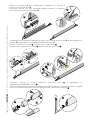
Collegamento al modulo Wireless
Collegamento al modulo trasmettitore da esterno 806TF-0060
Collegamento al quadro comando
Collegamento al quadro comando e scheda di controllo (DFI)
COLLEGAMENTI ELETTRICI
⚠ Predisporre i tubi corrugati necessari per i collegamenti.

CAME S.p.A.
Via Martiri Della Libertà, 15
31030 Dosson di Casier - Treviso - Italy
tel. (+39) 0422 4940 - fax. (+39) 0422 4941
Manuale FA 0173 5 -IT - 01/2022 - © CAME S.p.A. - I contenuti del manuale sono da ritenersi suscettibili di modifica in qualsiasi momento senza obbligo di preavviso.
DISMISSIONE E SMALTIMENTO
Prima di procedere è sempre opportuno verificare le normative specifiche vigenti nel luogo d’installazione. I componenti
dell’imballo (cartone, plastiche, etc.) sono assimilabili ai rifiuti solidi urbani e possono essere smaltiti senza alcuna dicoltà,
semplicemente eettuando la raccolta dierenziata per il riciclaggio.
Altri componenti (schede elettroniche, batterie dei trasmettitori, etc.) possono invece contenere sostanze inquinanti. Vanno
quindi rimossi e consegnati a ditte autorizzate al recupero e allo smaltimento degli stessi.
NON DISPERDERE NELL’AMBIENTE!
RISOLUZIONE DEI PROBLEMI
Problema Possibile causa Verifiche e rimedi
Il bordo non interviene Un cavo è danneggiato Rivolgersi all’assistenza (l’automazione non deve essere
usata)
Il bordo sensibile interviene
in ritardo Il micro è regolato male Rivolgersi all’assistenza
L’automazione non chiude. Il bordo è sollecitato
Un cavo è danneggiato
Verificare che non vi sia oggetti appoggiati al bordo o che
lo stesso non sia deformato (Rivolgersi all’assistenza).
MANUTENZIONE
☞ Prima di qualsiasi operazione di manutenzione, togliere la tensione, per evitare possibili situazioni di pericolo causate da
accidentali movimentazioni dell’automazione.
☞ Il bordo sensibile non necessità di manutenzioni particolari, ma è buona norma controllare periodicamente (ogni 6 mesi)
lo stato del profilo in gomma e verificare il funzionamento del dispositivo.
Se necessario pulire il dispositivo con un aspiratore o un panno umido (non usare solventi o detergenti).
⚠ Eventuali modifiche al dispositivo di sicurezza, possono determinare situazioni pericolose!

Sensitive safety-edge
DFWN1500 / 1700 / 2000 / 2500
DFWN1500N / 1700N / 2000N / 2500N
INSTALLATION MANUAL
EN
English
FA01753-EN

L
190
46
101
RV118I
RV118A
RV118N
RV118M
TMFW - TMFWN
TMF6W - TMF6WN
RV117H
p. 22 - Manual code FA01753- ENFA01753- EN - 01/2022 - © Came S.p.A. The contents of this manual may be changed at any time without prior notice.
IMPORTANT SAFETY INSTRUCTIONS WHEN INSTALLING
WARNING! IMPROPER INSTALLATION MAY RESULT IN SERIOUS DAMAGE, FOLLOW ALL INSTALLATION INSTRUCTIONS
THIS MANUAL IS EXCLUSIVELY INTENDED FOR PROFESSIONAL, SKILLED STAFF
LEGEND
Parts to read carefully.
⚠ Parts about safety.
☞ What to tell users.
REFERENCE REGULATIONS
The product complies to the reference regulations in effect.
DESCRIPTION
This product is designed and built by Came S.p.A. in conformity with current safety standards, and is PR&S n.04.363 certified
for vertical and horizontal applications.
The sensitive safety-edge consists of an aluminum support rail and a rubber edge and two rubber end caps. The rubber
edge houses two joined and jointed lever mechanism and one ø 1.3 mm steel cable.
Intended use
The sensitive safety-edge is made for preventing crushing or entrapment by gates. Detection happens along the entire
length of the edge, including the end caps.
Anyinstallation and/or use other than that specified in this manual is forbidden.
⚠ Thismanual is only intended for qualified technical staff or other persons trained in its installation.
Technical data
Type DFWN DFI
Protection rating (IP) 54 (fitted vertically)
44 (fitted horizontally) 56
Power supply (V) - 12-24 AC / DC
Fuse (mA) - 630
Operating temperature (°C) -20 ÷ +55 -20 ÷ +55
Apparatus class II II
Materials
CCA 48SHA heat-resistant rubber edge
SEBS 60SHA heat-resistant rubber end caps
POM jointed levers
Steel cable
Self-extinguishing
insulating tech-polymer
casing
Dimensions (mm)
DFWN1500
DFWN1500N
DFWN1700
DFWN1700N
DFWN2000
DFWN2000N
DFWN2500
DFWN2500N
DFWN
(RV117H+RV118I+TMFW)
(RV117H+RV118N+TMFWN)
DFWN
(RV117H+RV118A+TMF6W)
(RV117H+RV118M+TMF6WN)
1500 1700 2000 2500 4,000 max 6,000 max

DFWN
A
806TF-0060
(RX)
C
DFI
D
D
RIOED8WS
RIOED8WS
RIOCT8WS
DFWN
DFWN
DFWN
DFWN
B
D
806TF-0060
(TX)
C
p. 33 - Manual code FA01753- ENFA01753- EN - 01/2022 - © Came S.p.A. - The contents of this manual may be changed at any time without prior notice.
Standard installation
Connection Cable type Cable section
A C - NC
FROR CEI 20-22
CEI EN 50267-2-1
2 X 0.5 mm2
B C - NO - NC 3 X 0.5 mm2
C C - NC Power supply 12/24
V
4 X 0.5 mm2
D C - NC (Resistive 8.2 KOhm) 2 X 0.5 mm2
Main components
1. Rubber caps
2. Rubber edge
3. Steel cable
4. Cable clamping mechanism
5. Aluminum rail
6. Fastening bracket
7. Micro-switch housing mechanism
8. Micro
9. Electrical connection clamp
10. UNI6954 Ø 2.9x13 screws
11. UNI6954 Ø 3.9x13 screws
12. Fastening clamp

LP
LG
12
140
LOCK
UNLOCK
CAME
CAME
L N
L N
CAME
LN
LN - 30
30
4
3
5
150
4
3
5
150
ⒷⒶ
p. 44 - Manual code FA01753- ENFA01753- EN - 01/2022 - © Came S.p.A. The contents of this manual may be changed at any time without prior notice.
INSTALLATION
⚠ Before installing, check that the sensitive safety-edge is to be fastened onto a suitable surface.
Setting up the sensitive safety-edge.
For non standard length sensitive safety-edges, establish the LN or nominal length of the area you with to protect.
Warning! With vertical fittings, reduce the LN by 30 to the edge from scraping the ground.
Use a Ø 3-mm bt to drill the rail on either side for fitting the end caps .
Fit marked end of the cable-clamping mechanism into the rail and fasten it using the two UNI6955 Ø 3.9x13 screws .
Cut the rubber edge LG = LN - 285 mm .
⚠ Products DFWN1500/1700/2000/2500 have a narrowing on the aluminum rail Ⓐ. When assembling, mark the
aluminum rail 140 mm from the end. Use channellock pliers Ⓑ.
Cutthe aluminum rail at the opposite end of the point marked LP = LN - 40 mm .

8
9
10
7
6
11
12
13
14
17
15 16
p. 55 - Manual code FA01753- ENFA01753- EN - 01/2022 - © Came S.p.A. - The contents of this manual may be changed at any time without prior notice.
Fit the rubber edge into the aluminum rail until it stops against the mechanism .
Fit the steel cable into the rubber edge's upper hole .
Release the lever of the micro-switch housing mechanism by gently pressing down , fit the mechanism into the rail and
fasten it using the two UNI6955 Ø 3.9x13 screws .
Fit the steel cable into the clamp hole 11 and fit the clamp into the lever 12.
Tighten the cable by turning the grub screw in the clamp. 13Cut the excess cable 14.
Fit the end cap on the side of the cable clamping mechanism 15 and fasten it using the UNI 6954 ø 3.9 x 13 bolts and washers16.
When fitting vertically, to prevent moisture build-up inside the sensitive safety-edge, use a Ø 4 mm bit to drill the marked
holes on the end cap, before actually fitting it17.

2
13
Ø 2,5
5
4
6
7
Ø 2,5
5
4
6
7
1
2
3
4
10
11
20 mm
8
9
p. 66 - Manual code FA01753- ENFA01753- EN - 01/2022 - © Came S.p.A. The contents of this manual may be changed at any time without prior notice.
Fastening the sensitive safety-edge
Set up a Ø 10-mm corrugated connection tube .
Place the braces at equal distances from the center, mark and drill the fastening holes . Fasten the braces using Ø 4-mm
dowels and screws .
If necessary (for example, with metal structures), use washer head self tapping Ø 3.9-mm screws.
Drill the back of the aluminum rail and set up the passing of the electrical cable . Items: DFWN1500/1700/2000/2500
already have pre-drilled holes.
Use a probe to help the cable along the rail .
Place the sensitive-safety edge onto the braces (with the micro-switch holding mechanism facing up), drill on either side of
the rail using a Ø 2.5 mm bit and fasten it using the UNI 6954 Ø 2.9x13 screws. .
Make the electrical connections depending on the type of system (see electrical connections).
Adjust the tautness of the cable by turning the grub-screw on the micro-switch housing mechanism and check whether
the micro-switch is works correctly: it should activate after maximum 20 mm of deformation .
PROPER OPERATION:
- initial position ;
- micro-switch activation point (20 mm from the initial position), response time = 0.2 seconds ;
- maximum crushing position = 45 mm from the initial position ;
- initial position restoring time = 2 seconds .
Fasten the mechanism using a screw .
Fit the end cap and fasten it using UNI6954 Ø 3.9x13 screws and washers 11.

2C1
NCNC
DFWN
24V 0V NCNOC12V
NC
NOC
2C1 10 11
1
212
2
1DFWN
DFI
IN1 IN2
NCNO
C
NCNO
C
DFWN RIOED8WS RIOCT8WS
NCNO
C
NCNO
C
KKK
4
3
2
1
806TF-0060 (TX)
DFWN
806TF-0060 (RX)
p. 77 - Manual code FA01753- ENFA01753- EN - 01/2022 - © Came S.p.A. - The contents of this manual may be changed at any time without prior notice.
Connecting to the wireless module
Connecting to the 806TF-0060 outboard transmitter module
Connecting to the control panel
Connecting to the control panel and DFI control board
ELECTRICAL CONNECTIONS
⚠ Lay the corrugated tubes needed for making the connections.

CAME S.p.A.
Via Martiri Della Libertà, 15
31030 Dosson di Casier - Treviso - Italy
tel. (+39) 0422 4940 - fax. (+39) 0422 4941
Manual FA01753-ENFA01753- E N - 01/2022 - © Came S.p.A. The contents of this manual may be changed at any time without prior notice.
DISMANTLING AND DISPOSAL
Always make sure you comply with local laws before dismantling and disposing of the product. The packaging materials
(cardboard, plastic, and so on) should be disposed of as solid household waste, and simply separated from other waste for
recycling.
Whereas other components (control boards, batteries, transmitters, and so on) may contain hazardous pollutants. These must
therefore be disposed of by authorized, certified professional services.
DO NOT DISPOSE OF IN NATURE!
TROUBLESHOOTING
Problem Possible cause Checks and fixes
The edge does not activate A cable is damaged Call for technical assistance (the operator must not be
used in the meantime)
The sensitive safety-edge
activates late
The micro-switch is mis-
calibrated Call assistance
The operator does not
shut.
The edge is engaged
A cable is damaged
Check that no objects are resting against the edge or that
it is not deformed (call for assistance).
MAINTENANCE
☞ Before any maintenance jobs, cut off the mains power, to prevent possible hazards from unwanted movements by the
operator.
☞ The sensitive safety-edge does not need special maintenances, but periodical twice yearly checks are recommended,
as concerns the state of the rubber edge and to check how the device is performing.
You need to clean the device using a vacuum cleaner or a moist cloth. Do not use solvents or detergents.
⚠ Any modifications to this safety device may result in hazards.

Bord sensible de sécurité
DFWN1500 / 1700 / 2000 / 2500
DFWN1500N / 1700N / 2000N / 2500N
MANUEL D'INSTALLATION
FR
Français
FA01753-FR

L
190
46
101
RV118I
RV118A
RV118N
RV118M
TMFW - TMFWN
TMF6W - TMF6WN
RV117H
Page 22 - Code manuel FA01753-FRFA01753- FR - 01/2022 - © Came S.p.A. - Le contenu du manuel est susceptible de subir des modifications à tout moment et sans aucun préavis
INSTRUCTIONS IMPORTANTES DE SÉCURITÉ POUR L'INSTALLATION
ATTENTION ! UNE INSTALLATION INCORRECTE PEUT PROVOQUER DE GRAVES DOMMAGES, SUIVRE TOUTES LES INSTRUCTIONS D'INSTALLATION
LE PRÉSENT MANUEL N'EST DESTINÉ QU'À DES INSTALLATEURS PROFESSIONNELS OU À DES PERSONNES COMPÉTENTES
LÉGENDE
Parties à lire attentivement.
⚠ Parties concernant la sécurité.
☞ Ce que l'utilisateur doit savoir.
RÉFÉRENCES NORMATIVES
Le produit est conforme aux directives de référence en vigueur.
DESCRIPTION
Ce produit a été conçu et fabriqué par la société Came S.p.A. conformément aux normes de sécurité en vigueur, et a été
certifié (PR&S n° 04.363) pour une application aussi bien verticale qu'horizontale.
Le bord sensible se compose d'un profilé de support en aluminium, d'un profilé et de deux embouts en caoutchouc. Le profilé
en caoutchouc contient deux mécanismes à leviers articulés unis par un câble en acier (ø 1,3 mm).
Utilisation prévue
Le bord sensible de sécurité est une protection contre le risque d'écrasement et de coincement. La détection a lieu par
contact sur toute la longueur du bord, y compris les embouts.
Toute installation et toute utilisation autres que celles qui sont indiquées dans ce manuel sont interdites.
⚠ Le présent manuel s'adresse uniquement au personnel technique professionnel ou aux personnes préposées à
l'installation.
Données techniques
Type DFWN DFI
Degré de protection (IP) 54 (fixé verticalement)
44 (fixé horizontalement) 56
Alimentation (V) - 12-24 AC / DC
Fusible (mA) - 630
Température de fonctionnement (°C) -20 à +55 -20 à +55
Classe de l’appareil II II
Matériaux
Profilé en caoutchouc thermoplastique CCA 48SHA
Embouts en caoutchouc thermoplastique SEBS 60SHA
Leviers articulés POM
Câble en acier
Boîtier en
technopolymère isolant
auto-extinguible
Dimensions (mm)
DFWN1500
DFWN1500N
DFWN1700
DFWN1700N
DFWN2000
DFWN2000N
DFWN2500
DFWN2500N
DFWN
(RV117H+RV118I+TMFW)
(RV117H+RV118N+TMFWN)
DFWN
(RV117H+RV118A+TMF6W)
(RV117H+RV118M+TMF6WN)
1500 1700 2000 2500 4000 max. 6000 max.

DFWN
A
806TF-0060
(RX)
C
DFI
D
D
RIOED8WS
RIOED8WS
RIOCT8WS
DFWN
DFWN
DFWN
DFWN
B
D
806TF-0060
(TX)
C
Page 33 - Code manuel FA01753-FRFA01753- FR - 01/2022 - © Came S.p.A. - Le contenu du manuel est susceptible de subir des modifications à tout moment et sans aucun préavis.
Installation standard
Connexion Type câble Section câble
A F - NF
FROR CEI 20-22
CEI EN 50267-2-1
2 X 0,5 mm²
B F - NO - NF 3 X 0,5 mm²
C F - NF Alimentation 12/24
V
4 X 0,5 mm²
D F - NF (Résistive 8,2 KOhms) 2 X 0,5 mm²
Composants principaux
1. Embouts en caoutchouc
2. Profilé en caoutchouc
3. Câble en acier
4. Mécanisme de fixation du câble
5. Profilé en aluminium
6. Étrier de fixation
7. Mécanisme de support du micro-
interrupteur
8. Micro-interrupteur
9. Borne de connexion électrique
10. Vis UNI6954 Ø 2,9x13
11. Vis UNI6954 Ø 3,9x13
12. Bride de fixation

LP
LG
12
140
LOCK
UNLOCK
CAME
CAME
L N
L N
CAME
LN
LN - 30
30
4
3
5
150
4
3
5
150
ⒷⒶ
Page 44 - Code manuel FA01753-FRFA01753- FR - 01/2022 - © Came S.p.A. - Le contenu du manuel est susceptible de subir des modifications à tout moment et sans aucun préavis
INSTALLATION
⚠ Avant l'installation, s'assurer que le point de fixation du bord sensible se trouve bien sur une surface adéquate.
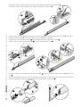
Préparation du bord sensible
Pour des bords sensibles d'une longueur non standard, déterminer la longueur nominale (LN) de la zone à protéger.
Attention ! En cas d'application verticale, réduire la longueur nominale (LN) de 30 mm pour éviter tout contact avec le sol.
Percer le profilé à l'aide d'une mèche d'un diamètre de 3 mm des deux côtés pour la fixation des embouts .
Introduire le mécanisme de fixation du câble dans le profilé du côté indiqué et le fixer à l'aide des deux vis UNI6955
Ø 3,9x13 .
Couper le profilé en caoutchouc LG = LN - 285 mm .
⚠ Les produits DFWN1500/1700/2000/2500 présentent un pincement sur les profilés en aluminium Ⓐ. Sur ceux à
assembler, marquer le profilé à l’aide d’une pince multiprise, à 140 mm de l’extrémité Ⓑ.
Couper le profilé en aluminium du côté opposé à celui du point marqué LP = LN - 40 mm .
La pagina si sta caricando...
La pagina si sta caricando...
La pagina si sta caricando...
La pagina si sta caricando...
La pagina si sta caricando...
La pagina si sta caricando...
La pagina si sta caricando...
La pagina si sta caricando...
La pagina si sta caricando...
La pagina si sta caricando...
La pagina si sta caricando...
La pagina si sta caricando...
-
 1
1
-
 2
2
-
 3
3
-
 4
4
-
 5
5
-
 6
6
-
 7
7
-
 8
8
-
 9
9
-
 10
10
-
 11
11
-
 12
12
-
 13
13
-
 14
14
-
 15
15
-
 16
16
-
 17
17
-
 18
18
-
 19
19
-
 20
20
-
 21
21
-
 22
22
-
 23
23
-
 24
24
-
 25
25
-
 26
26
-
 27
27
-
 28
28
-
 29
29
-
 30
30
-
 31
31
-
 32
32


in altre lingue
- français: CAME DFWN Guide d'installation
- русский: CAME DFWN Инструкция по установке
Documenti correlati
-
CAME DFWN Guida d'installazione
-
-
-
-
-
-
-
-
-
