
Il bordo sensibile è formato da un prolo in gomma termoplastica (TPE) con dopocorsa elastico di ammortamento urto
superiore ai 30 mm e da un prolo in alluminio che ssato alla colonna o al cancello funge da supporto all'estruso in gomma.
Il funzionamento del dispositivo è garantito da due micro-switches. Il primo lavora su deformazione della gomma e del supporto
inferiore, il secondo come sicurezza nel caso in cui il cavetto di acciaio perdesse tensione.
Attenzione: Il dispositivo elettromeccanico di rilevamento ostacoli è un dispositivo di sicurezza “ausiliario”. Vale a
dire che è utilizzabile su impianti comandati a “uomo presente” oppure in conformità ai requisiti dettati dalla Norma di
Sicurezza EN12453.
Pag.4-4
Rev. 15-00
DISPOSITIVO MECCANICO
DI RILEVAMENTO OSTACOLI
QK-CSASC150 / 200
In condizione di riposo nessuno dei due microinteruttori dovrà essere premuto
QUOTE FISSAGGIO BORDO (tutte le misure sono espresse in mm)
ALTEZZA BORDO (HT) H1 H2 H3
1500 5 710 1416
2000 5 960 1916
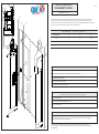
MONTAGGIO
Fissare la staa (A2) alla colonna, facendo riferimento alle quote riportare nella tabella.
Collocare il bordo sensibile in posizione e ssarlo utilizzando i fori predisposti (A1,A3)
Tarare il bordo sensibile (vedi taratura)
Collegare il dispositivo (vedi collegamenti)
Inserire la calotta di copertura (A4) come da gura
TARATURA
Per modicare la sensibilità del bordo sensibile operare nel seguente modo
Sbloccare il controdado (C1)
Regolare la sensibilità del bordo agendo sul tendicavo (C2).
Ribloccare il controdado (C1)
H1
H2
H3
A2
A1
A3
A4
HT
C.1
C.2
C.3
COLLEGAMENTI
Montato il Bordo Sensibile alla colonna o al cancello, eseguire il collegamento della costa dai morsetti (C3, contatto NC) al
contatto di sicurezza della centrale di comando del motore.

Pag.3-4Pag.2-4
La barre sensible BS01 est composée d'un prolé en caoutchouc thermoplastique (TPE) avec un dispositif élastique pour amortir
le choc supérieur de 30 mm et d'un prolé en alluminium que, une fois xé au pilier, sera le support du prolé en caoutchouc.
Le fonctionnement de la barre est garanti par deux micro-interrupteurs. Le premier intervient dans le cas où le caoutchouc ou son
support inférieur seraient déformés, le deuxième dans le cas où le petit câble en acier perdrait de tension.
The BS01 mechanic safety edge is made of a thermoplastic rubber (TPE) elastic after shock 30 mm high edge and of an
alluminium prole. The alluminium prole, which is xed to the post, oers support to the rubber.
The electromechanical safety edge has two microswitches which guarantee its working. The rst one works on the distorsion of
the rubber and of the lower part of the BS01; the second one stops the automation if the steel thread release.
Attention : le dispositif pour relèvement des obstacles est un dispositif de sécurité supplementaire. Le bord
sensible doit être utilisé sur des équipements contrôlés par un opérateur ou en conformité à la Norme de Securité
EN12453.
Attention: the electromechanical device is an “auxiliary” safety device. The border must be used on equipments
controlled by an operator or according to the standards of the Safety Standard EN 12453.
DISPOSITIF ELECTROMECANIQUE
POUR RELEVER LES OBSTACLES
ELECTROMECHANICAL
OBSTACLE-SENSING DEVICE
QK-CSASC150/200
En position de repos pas de micro-interrupteur doit être appuyé.
INSTALLATION
Fixer la plaque (A2) sur le montant, suivant les niveaux du tableau ci-dessu
Insérer le bord sensible et le xer en utilisant les troux préparés (A1,A3)
Tarer le bord sensible (voir Tarage)
Connecter le dispositif (voir Connexions)
Insérer le couvercle selon (A4) le dessin
TARAGE
An de modier la sensibilité du bord agir selon les instructions suivantes
Débloquer le contre-écrou (C1)
Vous pouvez régler la sensibilité de la barre en agissant sur le tendeur C2
Ri-bloquer le contre-écrou (C1)
In the o position do not press any microswitch
INSTALLATION
Fix the support (A2) on the post paying attention to the indication on the table above
Insert the extrusion in the support and x in the hole predispositioned (A1,A3)
Set the sensitivity of the device (see Setting Instructions)
Connect the device (see Connections)
Insert the cap (A4) as shown
SETTING INSTRUCTION
In order to modify the sensitivity of the edge do the following operations
Unblock the nut (C1)
You can adjust the sensitivity of the edge acting on the tensioner C2
Tighter the nut (C1)
CONNECTIONS
After mounting the Sensitive Edge to the post or at the gate, connecting the terminals (C3, NC contact) to the safety
contact of the control unit of the engine.
NIVEAUX D'INSTALLATION DU BORD (Toutes les mesures sont exprimées en mm)
H BORD (HT) H1 H2 H3
1500 5 710 1416
2000 5 960 1916
INSTALLATION HEIGHT (all measures are expressed in mm)
HEIGHT OF EDGE (HT) H1 H2 H3
1500 5 710 1416
2000 5 960 1916
CONNEXIONS
Après le montage du bord à la poste ou à la grille, reliez les terminaux (C3, contact NC) au contact de sécurité de l'unité de
contrôle du moteur .
QK-CSASC150/200
-
 1
1
-
 2
2


in altre lingue
- English: quiko QK-CSASC150 200 User manual
Altri documenti
-
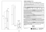 SEAV TP52 Manuale utente
-
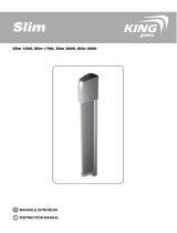 KINGgates Slim Manuale del proprietario
-
V2 Elettronica V2 Touch CMM Manuale del proprietario
-
Telcoma TAG Manuale del proprietario
-
-
CAME DFWN Guida d'installazione
-
-
-
Nice Automation Run Manuale del proprietario
-

