SICK WTL16 / WTS16 Istruzioni per l'uso
- Categoria
- Illuminazione di comodità
- Tipo
- Istruzioni per l'uso


Described product
W16
WTL16, WTS16
Manufacturer
SICK AG
Erwin-Sick-Str. 1
79183 Waldkirch
Germany
Legal information
This work is protected by copyright. Any rights derived from the copyright shall be
reserved for SICK AG. Reproduction of this document or parts of this document is
only permissible within the limits of the legal determination of Copyright Law. Any modi‐
fication, abridgment or translation of this document is prohibited without the express
written permission of SICK AG.
The trademarks stated in this document are the property of their respective owner.
© SICK AG. All rights reserved.
Original document
This document is an original document of SICK AG.
2006/42/EC
NO
SAFETY
2
8020347.19RH / 22.12.2020 | SICK
Subject to change without notice

Contents
1 Safety information............................................................................ 4
1.1 General safety notes................................................................................ 4
1.2 Notes on UL approval............................................................................... 4
2 Intended use...................................................................................... 4
3 Operating and status indicators...................................................... 4
4 Mounting............................................................................................. 5
5 Electrical installation........................................................................ 5
6 Additional functions.......................................................................... 7
7 Commissioning.................................................................................. 8
7.1 Alignment.................................................................................................. 8
7.2 Check the application conditions............................................................ 8
7.3 Sensing range setting............................................................................... 9
7.4 Time function setting................................................................................ 13
7.5 Setting light/dark switching..................................................................... 14
8 Process data structure..................................................................... 14
9 Troubleshooting................................................................................. 14
10 Disassembly and disposal............................................................... 15
11 Maintenance...................................................................................... 15
12 Technical data.................................................................................... 16
12.1 Dimensional drawings.............................................................................. 16
CONTENTS
8020347.19RH / 22.12.2020 | SICK
Subject to change without notice
3

1 Safety information
1.1 General safety notes
■
Read the operating instructions before commissioning.
■
Connection, mounting, and configuration may only be performed by trained
specialists.
■
2006/42/EC
NO
SAFETY
Not a safety component in accordance with the EU Machinery Directive.
■
Do not install the sensor at locations that are exposed to direct sunlight
or other weather influences, unless this is expressly permitted in the operating
instructions.
■
These operating instructions contain information required during the life cycle of
the sensor.
1.2 Notes on UL approval
The device shall be supplied from an isolating transformer having a secondary overcur‐
rent protective device that complies with UL 248 to be installed in the field rated either:
a) max 5 amps for voltages 0 ~ 20 V (0 ~ 28.3 V peak), or
b) 100 / Vp for voltages of 20 ~ 30 V (28.3 ~ 42.4 V peak).
Alternatively, they can be supplied from a Class 2 power supply.
UL Environmental Rating: Enclosure type 1
2 Intended use
The WTL16, WTS16 is an opto-electronic photoelectric proximity sensor (referred to as
“sensor” in the following) for the optical, non-contact detection of objects, animals,
and persons. If the product is used for any other purpose or modified in any way, any
warranty claim against SICK AG shall become void.
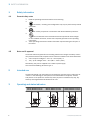
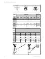
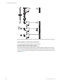
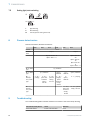
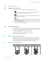
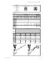
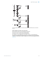
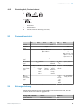
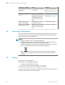
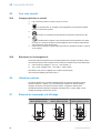
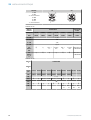
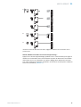
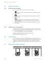
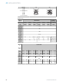
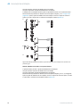
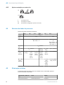
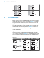
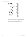
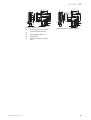
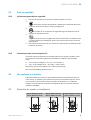
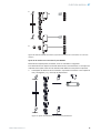
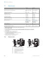
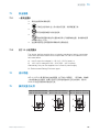
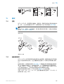
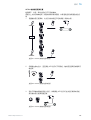
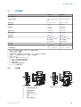
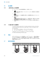
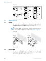
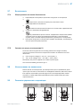
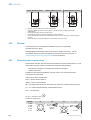
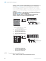
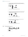
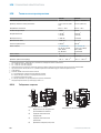
3 Operating and status indicators
WTL16, WTS16x-xxxxxx10
WTL16, WTS16x-xxxxxx20
WTL16, WTS16x-xxxxxx11
WTL16, WTS16x-xxxxxx21
WTL16, WTS16x-xxxxxx12
WTL16, WTS16x-xxxxxx22
2
3
4
1
2
1
4
3
6
2
1
4
3
5
1 SAFETY INFORMATION
4
8020347.19RH / 22.12.2020 | SICK
Subject to change without notice

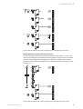
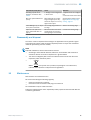
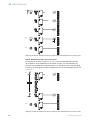
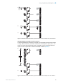
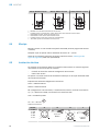
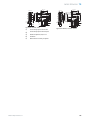
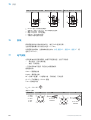
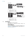
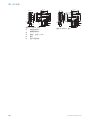
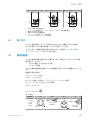
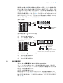
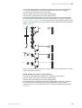
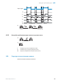
WTL16, WTS16x-xxxxxx30 WTL16, WTS16x-xxxxxx31 WTL16, WTS16x-xxxxxx32
2
1
4
3
2
1
3
4
6
2
1
3
4
5
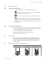
1
BluePilot blue: sensing range display
2
Press-turn element / Potentiometer / Teach-Button: adjusting the sensing range
3
LED indicator yellow: status of received light beam
4
LED indicator green: supply voltage active
5
Press-turn element: time function adjustment
6
Teach pushbutton: adjustment of light/dark switching
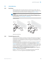
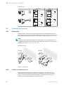
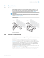
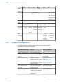
4 Mounting
Mount the sensor using a suitable mounting bracket (see the SICK range of acces‐
sories).
Note the sensor’s maximum permissible tightening torque of < 1,3 Nm.
Note the preferred direction of the object relative to the sensor, see figure 11, figure 12,
figure 13 (only applies for WTS16).
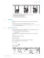
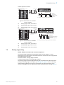
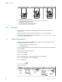
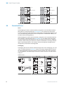
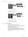
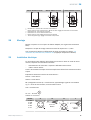
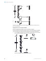
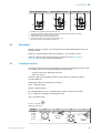
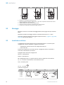
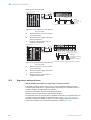
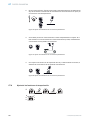
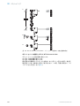
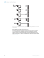
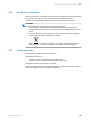
5 Electrical installation
The sensors must be connected in a voltage-free state. The following information must
be observed, depending on the connection type:
– Male connector connection: Note pin assignment.
– Cable: wire color
Only supply/switch on the voltage once all electrical connections have been estab‐
lished.
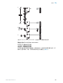
Explanations on connection diagram:
Alarm = alarm output
Health = alarm output
MF (pin 2 configuration) = external input, teach-in, switching signal
Q
L1
/C = switching output, IO-Link communication
Test = test input
U
B
: 10 ... 30 V DC
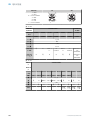
Table 1: Connections
Wxx16x- x4 xH x5 xI
1 = BN
2 = WH
3 = BU
4 = BK
5= GY
1
2
4 3
0.14 mm
2
AWG26
1
2
4 3
5
0.14 mm
2
AWG26
MOUNTING 4
8020347.19RH / 22.12.2020 | SICK
Subject to change without notice
5

Wxx16x- x9 xB
1 = BN
2 = BU
3 = not connected
4 = BK
5= WH
6 = GY
7 = not connected
3 4
1
2 5
6
I
N
= 4 A
3
7
2
1
6
5
4
I
N
= 6 A
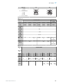
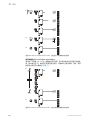
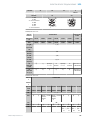
Table 2: DC
WTL16x-
WTS16x-
xxX6XxxxA00 xxX6XxxxA0
1-A99
Push-pull xx161 xx162 xx168 xx16A xx16L xx16N xx16x
PNP xx861 xx862 xx868 xx86A xx86L xx86N xx86x
1 = BN + (L+)
2 = WH MF
3 = BU - (M)
4 = BK Q
L1
/C
Default:
MF
Q
Q Test →
L+
no func‐
tion
Test →
L+
no func‐
tion
www.sick.co
m 8022709
Default:
Q
L1
/C
Q
Q
Q Q
Q Q
www.sick.co
m 8022709
Table 3: DC
WTL16
x-
WTS16
x-
xxXXXxxxZZZ
Push-
pull
xx111 xx112 xx113 xx114 xx115 xx116 xx421 xx422 xx721 xx722
PNP xx811 xx812 xx813 xx814 xx815 xx816 xxB21 xxB22 - -
BN + (L+)
WH
Q
Q Alarm Health Alarm Health
Q
Q
Q
Q
BU - (M)
BK Q
Q
Q Q
Q Q
Q
Q
Q
Q
GR - - - - - - Test →
L+
Test →
L+
Test →
M
Test →
M
Table 4: Push-pull, PNP, NPN
5
ELECTRICAL INSTALLATION
6
8020347.19RH / 22.12.2020 | SICK
Subject to change without notice

Push-pull
PNP
NPN
+ (L+)
Q ≤ 100 mA
‒ (M)
Push-pull
PNP
NPN
+ (L+)
Q ≤ 100 mA
‒ (M)
Push-pull
PNP
NPN
+ (L+)
Q ≤ 100 mA
‒ (M)
Push-pull
PNP
NPN
+ (L+)
Q ≤ 100 mA
‒ (M)
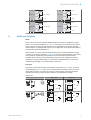
6 Additional functions
Alarm
Alarm output: The sensor (WTL16, WTS16) features a pre-failure notification output
(“Alarm” in connection diagram [see table 3]), which issues a notification if the sensor
is only ready for operation to a limited extent. The LED flashes in this case. Possible
causes: Sensor is contaminated, sensor is out of alignment. In the good state: LOW (0),
if excessively contaminated HIGH (1).
Health output: The sensor (WTL16, WTS16) features a pre-failure notification output
(“Health” in connection diagram [see table 3]), which issues a notification if the sensor
is only ready for operation to a limited extent or the cable has been interrupted.
Possible causes: Sensors are contaminated, sensors are out of alignment, cable is
damaged. In the good state: HIGH (1), if excessively contaminated or in the event of
cable interruption LOW (0). The LED flashes in this case.
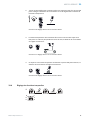
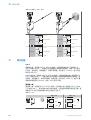
Test input
Test input: The WTL16, WTS16 sensors feature a test input (“TI” or “Test” on the con‐
nection diagram [table 2], which can be used to switch the sender off and, therefore,
check that the sensor is functioning correctly: If female cable connectors with LED
indicators are used, you have to ensure that the TI is assigned accordingly.
Table 5: Test
Test → M Test → L+
+ (L+)
Test
– (M)
+ (L+)
Test
– (M)
+ (L+)
Test
– (M)
+ (L+)
Test
– (M)
ADDITIONAL FUNCTIONS 6
8020347.19RH / 22.12.2020 | SICK
Subject to change without notice
7

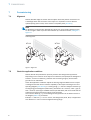
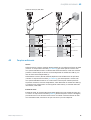
7 Commissioning
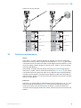
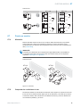
7.1 Alignment
WTL16, WTS16P: Align the sensor with the object. Select the position so that the red
emitted light beam hits the center of the object. It is important to ensure that the
optical opening (front screen) of the sensor is completely clear [see table].
NOTE
For WTS16: If the objects are detected from above, we recommend installing the sen‐
sor at an angle in order to prevent total reflection by a reflective surface, see figure 7 -
figure 10.
Table: Alignment
WTL16 WTS16
Figure 1: Alignment
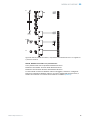
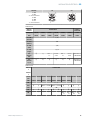
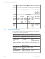
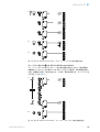
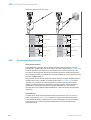
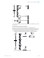
7.2 Check the application conditions
WTL16, WTS16 are photoelectric proximity sensors with background suppression.
Depending on the remission of the object to be detected, and perhaps the background
behind it, a minimum distance (y) between the set sensing range (x) and the back‐
ground is to be maintained.
Check the application conditions: Adjust the sensing range and distance to the object
or background as well as the remission capability of the object according to the corre‐
sponding diagram [see table 6] (x = sensing range, y = minimum distance between set
sensing range and background (white 90%)). Remission: 6% = black 1, 18% = gray 2,
90% = white 3 (referring to standard white as per DIN 5033). We recommend that the
adjustment be performed with an object of low remission.
The minimum distance (= y) for the background suppression can be determined from
the diagram [table 6 1] as follows:
Example: x = 200 mm, y = 15 mm. That is, the background (white, 90%) is suppressed
at a distance of > 15 mm of the configured sensing range.
7 COMMISSIONING
8
8020347.19RH / 22.12.2020 | SICK
Subject to change without notice

Table 6: Application conditions
0
10
5
35
30
25
20
15
45
40
50
100
(3.94)
200
(7.87)
300
(11.81)
600
(23.62)
400
(15.75)
500
(19.69)
0
Distance in mm (inch)
1
2
3
WTL16P-xxxxx1xx
18%/90%
6%/90%
90%/90%
Minimum distance in mm (y) between the set sensing
range and background (white, 90%)
y
x
yx
white background (90%)
Example:
Sensing range on black, 6%,
x = 200 mm, y = 15 mm
Figure 2: Characteristic line 1, WTL16P-
xxxxx1xx, red light
1
Sensing range on black, 6% remission
2
Sensing range on gray, 18% remission
3
Sensing range on white, 90% remission
100
(3.94)
200
(7.87)
Adjustment range
Distance in mm (inch)
A
300
(11.81)
400
(15.75)
500
(19.69)
0
1
2
3
50 300
25 400
10
500
BluePilot:
Sensing range
indicator (blue LED)
Teach-Turn
adjustment
A = Detection distance (depending on object remission)
100
100
100
0
20
10
60
50
40
30
80
70
90
200
(7.87)
400
(15.75)
600
(23.62)
1,000
(39.37)
800
(31.5)
0
1
2
3
WTS16P-xxxxx1xx
18%/90%
6%/90%
90%/90%
y
x
yx
Minimum distance in mm (y) between the set sensing
range and background (white, 90%)
white background (90%)
Example:
Sensing range on black, 6%,
x = 300 mm, y = 20 mm
Distance in mm (inch)
Figure 3: Characteristic line 1, WTS16P-
xxxxx1xx, red light
1
Sensing range on black, 6% remission
2
Sensing range on gray, 18% remission
3
Sensing range on white, 90% remission
100
(3.94)
400
(15.75)
200
(7.87)
A
800
(31.5)
1,000
(39.37)
1,500
(59.06)
0
1
2
3
400
10 500
10
750
BluePilot:
Adjustment range
Distance in mm (inch)
Sensing range indicator
(blue LED)
Teach-Turn adjustment
A = Detection distance (depending on object remission)
100
100
10015
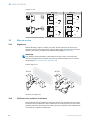
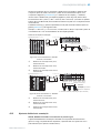
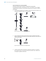
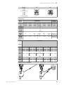
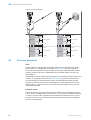
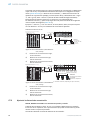
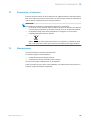
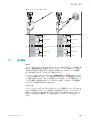
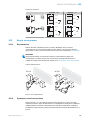
7.3 Sensing range setting
WTL16, WTS16x-xxxxxx2xAxx with Teach-Turn adjustment:
The sensing range is adjusted by pressing the teach-in button (approx. 1-3 sec.).
Depending on the requirements, the potentiometer can be used for fine-tuning (without
pressing the teach-in button).
Clockwise rotation: Sensing range increased.
Counterclockwise rotation: Sensing range reduced.
The sensing range can also be adjusted using just the potentiometer. We recommend
placing the sensing range in the object, e.g. see figure 4, page 10. Once the sensing
range has been adjusted, the object is removed from the path of the beam, which
causes the background to be suppressed and the switching output to change (table 4).
COMMISSIONING 7
8020347.19RH / 22.12.2020 | SICK
Subject to change without notice
9

1...3 sec.
1
2
3
Figure 4: WTL16, WTS16x-xxxxxx2xAxx, adjusting the sensing range with Teach-Turn adjustment
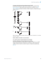
WTL16, WTS16x-xxxxxx1xAxx with potentiometer:
The sensing range is adjusted with the potentiometer.
Clockwise rotation: Sensing range increased.
Counterclockwise rotation: Sensing range reduced.
We recommend placing the object within the sensing range, see figure 9 for an exam‐
ple. Once the sensing range has been adjusted, the object is removed from the path of
the beam, which causes the background to be suppressed and the switching output to
change (table 4).
7 COMMISSIONING
10
8020347.19RH / 22.12.2020 | SICK
Subject to change without notice

1
2
3
Figure 5: WTL16, WTS16x-xxxxxx1xAxx, adjusting the sensing range with potentiometer
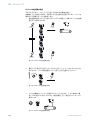
WTL16, WTS16x-xxxxxx3xAxx with teach-in button:
The sensing range is adjusted by pressing the teach-in button (approx. 1-3 sec.). We
recommend placing the object within the sensing range, see figure 10 for an example.
Once the sensing range has been adjusted, the object is removed from the path of
the beam, which causes the background to be suppressed and the switching output to
change (table 4).
1...3 sec.
1
2
Figure 6: WTL16, WTS16x-xxxxxx3xAxx, adjusting the sensing range with teach-in button
COMMISSIONING
7
8020347.19RH / 22.12.2020 | SICK
Subject to change without notice
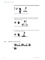
11

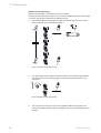
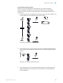
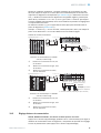
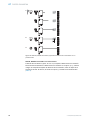
WTS16 sensing range setting
Detection of flat, glossy, contrast-rich, and uneven objects.
If the objects are detected from above, we recommend installing the sensor at an angle
in order to prevent total reflection by a reflective surface
1 When adjusting the sensing range, the light spot should be focused on an even,
uniform surface, e.g. a white sheet of paper.
1...3 sec.
Figure 7: WTS16 sensing range setting
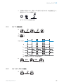
2 Turn the potentiometer a fraction counterclockwise until the yellow LED indicator
no longer lights up. The sensing range is now located a fraction above the con‐
veyor belt.
Figure 8: WTS16 sensing range setting
3 The conveyor belt should now be put into operation without any objects. If the
yellow LED indicator does not light up during the test run, the sensing range is set
correctly.
7
COMMISSIONING
12
8020347.19RH / 22.12.2020 | SICK
Subject to change without notice

Figure 9: WTS16 sensing range setting
4 If the object is in the path of the beam and the yellow LED indicator lights up, the
sensing range is set correctly.
Figure 10: WTS16 sensing range setting
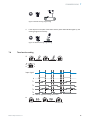
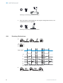
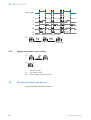
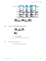
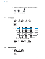
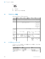
7.4 Time function setting
1
0
T1
T2
M
T4
T3
t
t
t t t
t
t t t t
t t t
t
t
t t
Input signal
0
T1
T2
T3
T4
M = Manual (specific setting via IO-Link)
1 ms 30.000 ms
2
COMMISSIONING 7
8020347.19RH / 22.12.2020 | SICK
Subject to change without notice
13

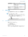
7.5 Setting light/dark switching
1
L
D
M
L light switching
D Dark switching
M manual (specific setting via IO-Link)
8 Process data structure
WTL16x-xxxxxxxxAxx, WTS16x-xxxxxxxxAxx:
A00 A70 A71 A72 A73 A75
IO-Link V1.1
Process
data
2 bytes 4 bytes
Byte 0: bits 15... 8
Byte 1: bits 7... 0
Byte 0: bits 31...
24
Byte 1: bits 13...
16
Byte 2: bits 15...
8
Byte 3: bits 7... 0
Bit 0 / Data
type
Q
L1
/ Boolean
Bit 1 / Data
type
Q
L2
/ Boolean Qint.1 /
Boolean
Q
L2
/
Boolean
Qint.1 / Boolean
Bit... /
Descrip‐
tion / Data
type
2 ...15 /
[empty]
2 ...15 /
[time mea‐
surement
value] /
UInt 14
2 … 15 /
[counter
value] /
UInt 14
2 … 15 /
[length /
speed
measure‐
ment] /
SInt14
2 /
Qint.1 /
Boolean
2 … 7 / [empty]
Bit... /
Descrip‐
tion / Data
type
3 … 15 /
[time mea‐
surement
value] /
UInt13
8 … 31 / [carrier
load] / UInt 24
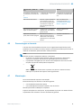
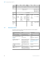
9 Troubleshooting
The Troubleshooting table indicates measures to be taken if the sensor stops working.
LED indicator/fault pattern Cause Measures
Green LED flashes IO-Link communication None
7 COMMISSIONING
14
8020347.19RH / 22.12.2020 | SICK
Subject to change without notice

LED indicator/fault pattern Cause Measures
Switching outputs do not
behave in accordance with
table 4
1. Change of the configuration
2. Short-circuit
1. Adjustment of the configura‐
tion
2. Check electrical connections
WTS only: yellow LED flashes
quickly
When adjusting the sensing
range, the light spot is only
half on the object or on a very
high-contrast object
Sensing range setting accord‐
ing to„WTS16 sensing range
setting“, page 12
Yellow LED lights up, no object
in the path of the beam
The sensing range distance is
too large
Reduce the sensing range
Object is in the path of the
beam, yellow LED does not
light up
Distance between the sensor
and the object is too long or
sensing range is set too short
Increase the sensing range
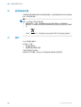
10 Disassembly and disposal
The sensor must be disposed of according to the applicable country-specific regula‐
tions. Efforts should be made during the disposal process to recycle the constituent
materials (particularly precious metals).
NOTE
Disposal of batteries, electric and electronic devices
•
According to international directives, batteries, accumulators and electrical or
electronic devices must not be disposed of in general waste.
•
The owner is obliged by law to return this devices at the end of their life to the
respective public collection points.
•
WEEE: This symbol on the product, its package or in this document,
indicates that a product is subject to these regulations.
11 Maintenance
SICK sensors are maintenance-free.
We recommend doing the following regularly:
•
Clean the external lens surfaces
•
Check the screw connections and plug-in connections
No modifications may be made to devices.
Subject to change without notice. Specified product properties and technical data are
not written guarantees.
DISASSEMBLY AND DISPOSAL 10
8020347.19RH / 22.12.2020 | SICK
Subject to change without notice
15

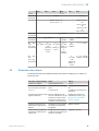
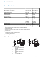
12 Technical data
WTL16P WTS16P
Sensing range max. 10 mm ... 500 mm
1)
10 mm ... 750 mm
1)
Light spot diameter/distance 3 mm x 30 mm (200
mm)
Ø 8 mm (300 mm)
Supply voltage U
B
DC 10 ... 30 V DC 10 ... 30 V
Ripple ≤ 5 V
SS
≤ 5 V
SS
Current consumption ≤ 30 mA
2)
< 50 mA
3)
≤ 30 mA
2)
< 50 mA
3)
Output current I
max.
≤ 100 mA ≤ 100 mA
Max. response time ≤ 500 µs
4)
≤ 1.4 ms
4)
Switching frequency 1,000 Hz
5)
350 Hz
5)
Enclosure rating
6)
see table 1:
x4, xH, x5, xI: IP66,
IP67, IP69
7)
x9, xB: IP65
see table 1:
x4, xH, x5, xI: IP66,
IP67, IP69
7)
x9, xB: IP65
Protection class III III
Circuit protection A, B, C, D
8)
A, B, C, D
8)
Ambient operating temperature –40 °C ... +60 °C
9)
–40 °C ... +60 °C
9)
1)
Object with 90 % remission (based on standard white DIN 5033)
2)
16 VDC to 30 VDC, without load
3)
10 VDC to 16 VDC, without load
4)
Signal transit time with resistive load in switching mode. Deviating values possible in COM2 mode.
5)
With a light/dark ratio of 1:1 in switching mode. Deviating values possible in IO-Link mode.
6)
Pursuant to EN 60529
7)
Replaces IP69 K pursuant to ISO 20653: 2013-03
8)
A = U
B
-connections reverse polarity protected
B = inputs and output reverse-polarity protected
C = Interference suppression
D = outputs overcurrent and short-circuit protected
9)
Do not bend cables below 0°C.
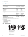
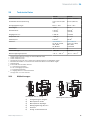
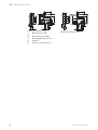
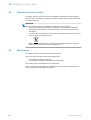
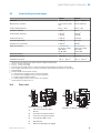
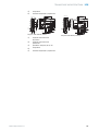
12.1 Dimensional drawings
5
4
3
2
1
16
(0.63)
18.5
(0.73)
20 (0.79)
Ø 12.9
(0.51)
Ø 4.1 (0.16)
39.9 (1.57)
55.4 (2.18)
45.5 (1.79)
5 (0.2)
42 (1.65)
29.9 (0.18)
6
(0.24)
3 (0.12)
6.5 (0.26)
15 (0.59)
27.8 (1.09)
7.7
(0.3)
7.8
(0.31)
7.2 (0.28)
35.5 (1.4)
4.1 (0.16)
8.3
(0.33)
55.7 (2.19)
6
Figure 11: WTL16, cable
1
Preferred direction of the target
object
2
Center of optical axis, sender
3
Center of optical axis, receiver
4
Fixing hole, Ø4.1 mm
5
Connection
6
Display and setting elements
M12
5
4
3
2
1
17.5
(0.24)
20 (0.79)
18
(0.71)
18.5
(0.73)
16
(0.63)
Ø 4.1 (0.16)
7 (0.28)
39.9 (1.57)
55.4 (2.18)
55.7 (2.19)
45.5 (1.79)
5 (0.2)
29.9 (0.18)
52.9 (2.08)
6
(0.24)
3 (0.12)
6.5 (0.26)
15 (0.59)
28 (1.1)
7.5
(0.3)
35.5 (1.4)
4.1 (0.16)
42 (1.65)
6
Figure 12: WTL16, male connector
12 TECHNICAL DATA
16
8020347.19RH / 22.12.2020 | SICK
Subject to change without notice

4
3
1
2
2
12.2 (0.48)
12.2 (0.48)
20 (0.79)
24.2 (0.95)
Ø 12.9
(0.51)
8.3
(0.33)
Ø 4.1 (0.16)
39.9 (1.57)
55.4 (2.18)
45.5 (1.79)
5 (0.2)
42 (1.65)
29.9 (0.18)
6
(0.24)
3 (0.12)
6.5 (0.26)
15 (0.59)
27.8 (1.09)
7.7
(0.3)
7.8
(0.31)
7.2 (0.28)
35.5 (1.4)
4.1 (0.16)
55.7 (2.19)
5
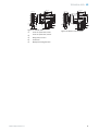
Figure 13: WTS16, cable
1
Center of optical axis, sender
2
Center of optical axis, receiver
3
Fixing hole, Ø 4.1 mm
4
Connection
5
Display and setting elements
M12
12.2 (0.48)
12.2 (0.48)
4
3
1
2
2
17.5
(0.24)
Ø 4.1 (0.16)
7 (0.28)
39.9 (1.57)
55.4 (2.18)
55.7 (2.19)
45.5 (1.79)
5 (0.2)
29.9 (0.18)
52.9 (2.08)
6
(0.24)
3 (0.12)
6.5 (0.26)
15 (0.59)
28 (1.1)
7.5
(0.3)
35.5 (1.4)
4.1 (0.16)
42 (1.65)
20 (0.79)
18
(0.71)
24.2 (0.95)
5
Figure 14: WTS16, male connector
TECHNICAL DATA 12
8020347.19RH / 22.12.2020 | SICK
Subject to change without notice
17


Beschriebenes Produkt
W16
WTL16, WTS16
Hersteller
SICK AG
Erwin-Sick-Str. 1
79183 Waldkirch
Deutschland
Rechtliche Hinweise
Dieses Werk ist urheberrechtlich geschützt. Die dadurch begründeten Rechte bleiben
bei der Firma SICK AG. Die Vervielfältigung des Werks oder von Teilen dieses Werks
ist nur in den Grenzen der gesetzlichen Bestimmungen des Urheberrechtsgesetzes
zulässig. Jede Änderung, Kürzung oder Übersetzung des Werks ohne ausdrückliche
schriftliche Zustimmung der Firma SICK AG ist untersagt.
Die in diesem Dokument genannten Marken sind Eigentum ihrer jeweiligen Inhaber.
© SICK AG. Alle Rechte vorbehalten.
Originaldokument
Dieses Dokument ist ein Originaldokument der SICK AG.
2006/42/EC
NO
SAFETY
8020347.19RH / 22.12.2020 | SICK
Subject to change without notice
19
La pagina si sta caricando...
La pagina si sta caricando...
La pagina si sta caricando...
La pagina si sta caricando...
La pagina si sta caricando...
La pagina si sta caricando...
La pagina si sta caricando...
La pagina si sta caricando...
La pagina si sta caricando...
La pagina si sta caricando...
La pagina si sta caricando...
La pagina si sta caricando...
La pagina si sta caricando...
La pagina si sta caricando...
La pagina si sta caricando...
La pagina si sta caricando...
La pagina si sta caricando...
La pagina si sta caricando...
La pagina si sta caricando...
La pagina si sta caricando...
La pagina si sta caricando...
La pagina si sta caricando...
La pagina si sta caricando...
La pagina si sta caricando...
La pagina si sta caricando...
La pagina si sta caricando...
La pagina si sta caricando...
La pagina si sta caricando...
La pagina si sta caricando...
La pagina si sta caricando...
La pagina si sta caricando...
La pagina si sta caricando...
La pagina si sta caricando...
La pagina si sta caricando...
La pagina si sta caricando...
La pagina si sta caricando...
La pagina si sta caricando...
La pagina si sta caricando...
La pagina si sta caricando...
La pagina si sta caricando...
La pagina si sta caricando...
La pagina si sta caricando...
La pagina si sta caricando...
La pagina si sta caricando...
La pagina si sta caricando...
La pagina si sta caricando...
La pagina si sta caricando...
La pagina si sta caricando...
La pagina si sta caricando...
La pagina si sta caricando...
La pagina si sta caricando...
La pagina si sta caricando...
La pagina si sta caricando...
La pagina si sta caricando...
La pagina si sta caricando...
La pagina si sta caricando...
La pagina si sta caricando...
La pagina si sta caricando...
La pagina si sta caricando...
La pagina si sta caricando...
La pagina si sta caricando...
La pagina si sta caricando...
La pagina si sta caricando...
La pagina si sta caricando...
La pagina si sta caricando...
La pagina si sta caricando...
La pagina si sta caricando...
La pagina si sta caricando...
La pagina si sta caricando...
La pagina si sta caricando...
La pagina si sta caricando...
La pagina si sta caricando...
La pagina si sta caricando...
La pagina si sta caricando...
La pagina si sta caricando...
La pagina si sta caricando...
La pagina si sta caricando...
La pagina si sta caricando...
La pagina si sta caricando...
La pagina si sta caricando...
La pagina si sta caricando...
La pagina si sta caricando...
La pagina si sta caricando...
La pagina si sta caricando...
La pagina si sta caricando...
La pagina si sta caricando...
La pagina si sta caricando...
La pagina si sta caricando...
La pagina si sta caricando...
La pagina si sta caricando...
La pagina si sta caricando...
La pagina si sta caricando...
La pagina si sta caricando...
La pagina si sta caricando...
La pagina si sta caricando...
La pagina si sta caricando...
La pagina si sta caricando...
La pagina si sta caricando...
La pagina si sta caricando...
La pagina si sta caricando...
La pagina si sta caricando...
La pagina si sta caricando...
La pagina si sta caricando...
La pagina si sta caricando...
La pagina si sta caricando...
La pagina si sta caricando...
La pagina si sta caricando...
La pagina si sta caricando...
La pagina si sta caricando...
La pagina si sta caricando...
La pagina si sta caricando...
La pagina si sta caricando...
La pagina si sta caricando...
La pagina si sta caricando...
La pagina si sta caricando...
La pagina si sta caricando...
La pagina si sta caricando...
La pagina si sta caricando...
La pagina si sta caricando...
La pagina si sta caricando...
La pagina si sta caricando...
La pagina si sta caricando...
La pagina si sta caricando...
La pagina si sta caricando...
La pagina si sta caricando...
La pagina si sta caricando...
La pagina si sta caricando...
La pagina si sta caricando...
La pagina si sta caricando...
La pagina si sta caricando...
La pagina si sta caricando...
La pagina si sta caricando...
La pagina si sta caricando...
La pagina si sta caricando...
La pagina si sta caricando...
La pagina si sta caricando...
La pagina si sta caricando...
La pagina si sta caricando...
La pagina si sta caricando...
-
 1
1
-
 2
2
-
 3
3
-
 4
4
-
 5
5
-
 6
6
-
 7
7
-
 8
8
-
 9
9
-
 10
10
-
 11
11
-
 12
12
-
 13
13
-
 14
14
-
 15
15
-
 16
16
-
 17
17
-
 18
18
-
 19
19
-
 20
20
-
 21
21
-
 22
22
-
 23
23
-
 24
24
-
 25
25
-
 26
26
-
 27
27
-
 28
28
-
 29
29
-
 30
30
-
 31
31
-
 32
32
-
 33
33
-
 34
34
-
 35
35
-
 36
36
-
 37
37
-
 38
38
-
 39
39
-
 40
40
-
 41
41
-
 42
42
-
 43
43
-
 44
44
-
 45
45
-
 46
46
-
 47
47
-
 48
48
-
 49
49
-
 50
50
-
 51
51
-
 52
52
-
 53
53
-
 54
54
-
 55
55
-
 56
56
-
 57
57
-
 58
58
-
 59
59
-
 60
60
-
 61
61
-
 62
62
-
 63
63
-
 64
64
-
 65
65
-
 66
66
-
 67
67
-
 68
68
-
 69
69
-
 70
70
-
 71
71
-
 72
72
-
 73
73
-
 74
74
-
 75
75
-
 76
76
-
 77
77
-
 78
78
-
 79
79
-
 80
80
-
 81
81
-
 82
82
-
 83
83
-
 84
84
-
 85
85
-
 86
86
-
 87
87
-
 88
88
-
 89
89
-
 90
90
-
 91
91
-
 92
92
-
 93
93
-
 94
94
-
 95
95
-
 96
96
-
 97
97
-
 98
98
-
 99
99
-
 100
100
-
 101
101
-
 102
102
-
 103
103
-
 104
104
-
 105
105
-
 106
106
-
 107
107
-
 108
108
-
 109
109
-
 110
110
-
 111
111
-
 112
112
-
 113
113
-
 114
114
-
 115
115
-
 116
116
-
 117
117
-
 118
118
-
 119
119
-
 120
120
-
 121
121
-
 122
122
-
 123
123
-
 124
124
-
 125
125
-
 126
126
-
 127
127
-
 128
128
-
 129
129
-
 130
130
-
 131
131
-
 132
132
-
 133
133
-
 134
134
-
 135
135
-
 136
136
-
 137
137
-
 138
138
-
 139
139
-
 140
140
-
 141
141
-
 142
142
-
 143
143
-
 144
144
-
 145
145
-
 146
146
-
 147
147
-
 148
148
-
 149
149
-
 150
150
-
 151
151
-
 152
152
-
 153
153
-
 154
154
-
 155
155
-
 156
156
-
 157
157
-
 158
158
-
 159
159


SICK WTL16 / WTS16 Istruzioni per l'uso
- Categoria
- Illuminazione di comodità
- Tipo
- Istruzioni per l'uso
in altre lingue
- English: SICK WTL16 / WTS16 Operating instructions
- français: SICK WTL16 / WTS16 Mode d'emploi
- español: SICK WTL16 / WTS16 Instrucciones de operación
- Deutsch: SICK WTL16 / WTS16 Bedienungsanleitung
- русский: SICK WTL16 / WTS16 Инструкция по эксплуатации
- português: SICK WTL16 / WTS16 Instruções de operação
- 日本語: SICK WTL16 / WTS16 取扱説明書
Documenti correlati
-
SICK WTB16 Bluetooth® Istruzioni per l'uso
-
-
-
-
-
-
-
-
-