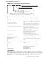
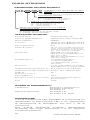
Eaton HVLD-4D Installation Instructions Manual
- Tipo
- Installation Instructions Manual

LVLD
MVLD
HVLD
Read these instructions carefully before
attempting a conversion or installation.
Keep these instructions for future
reference.
Installation Instructions
Conversion Kit LED


Table of Contents
Installation Instructions
Wiring ............................................ 4
Test options ................................... 4
Dimensions ....................................5
Telecommand ................................ 5
Indicating LED messages ..............5
Installation Instructions...................6
Denition of order codes ................6
Technical Specications ..................6
Standards ....................................... 6
Overview ........................................6
Preparation .....................................7
Component Layout Guidelines ....... 7
General Wiring Guidelines .............. 7
Terminal Connections ..................... 8
Testing the Conversion ................... 8
Commissioning & Routine Testing ..9
Batteries .........................................9
Output Current / Voltage
characteristics ............................... 10
Output Current / Voltage
diagrams ....................................... 12
Languages
English ............................................6
Croatian ........................................ 18
Czech ............................................ 22
Dutch ............................................ 26
French ........................................... 30
German .........................................34
Greek ............................................38
Hungarian .....................................42
Italian ............................................ 46
Portuguese ................................... 50
Romanian ......................................54
Serbian..........................................58
Slovenian ...................................... 62
Spanish .........................................66
SAFETY INSTRUCTIONS
• The device shall only be used for its
intended purpose and in undamaged
and awless condition.
• Only genuine Eaton spare parts may
be used for replacement and repair.
• Observe the national safety rules
and regulations to prevent accidents
as well as the safety instructions
included in these instruction leaet.

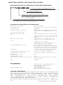
Conversion kit LED
4
CGL+
6
4
5
3
1
2
8
7
IN +
LED R
LED B
1h:
3h:
CV 12V:
CGLine+ Bus
OUT +
OUT -
IN -
Red
Brown
Indicating
Bicolor LED
CGL+
CGL+
6
4
5
3
1
2
8
7
IN +
LED Y
LED W
1h:
3h:
CV 12V:
DALI Bus
OUT +
OUT -
IN -
White
Yellow
DALI
Indicating
Bicolor LED
DALI
DALI
LE D
6
4
5
3
1
2
8
7
LED Y
LED W
TL B+
TL A-
IN -
OUT -
OUT +
IN +
-
+
9Vdc
Telecommand
6
4
5
3
1
2
8
7
LED Y
LED W
TL B+
TL A-
IN -
OUT -
OUT +
IN +
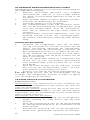
est by Normally Closed Switch
NC
Test options
6
4
5
3
1
2
8
7
IN +
LED
LED
1h:
3h:
CV 12V:
Bus
OUT +
OUT -
IN -
Brown/White
Red/Yellow
NC
CGL+/DALI
Indicating
Bicolor LED
6
4
5
3
1
2
8
7
LED Y
LED W
TL B+
TL A-
IN -
OUT -
OUT +
IN +
230Vac
-
+
9Vdc
Test by Telecommand
6
4
5
3
1
2
8
7
LED Y
LED W
TL B+
TL A-
IN -
OUT -
OUT +
IN +
230Vac
Test by Normally Closed Switch
6
4
5
3
1
2
8
7
LED Y
LED W
TL B+
TL A-
IN -
OUT -
OUT +
IN +
230Vac
Test by Normally Open Switch
NC
NO
6
4
5
3
1
2
8
7
LED Y
LED W
TL B+
TL A-
IN -
OUT -
OUT +
IN +
0Vac
Emergency to Rest by Telecommand
Telecommand Signal
-
+
9Vdc
=
TL A-
TL B+
-
+
9Vdc
=
TL A-
TL B+
Emergency
6
4
5
3
1
2
8
7
LED Y
LED W
TL B+
TL A-
IN -
OUT -
OUT +
IN +
0Vac
Telecommand Signal
Rest
6
4
5
3
1
2
8
7
IN +
LED
LED
1h:
3h:
CV 12V:
Bus
OUT +
OUT -
IN -
Red/White
Brown/Yellow
NC
Test by Normally Closed Switch
CGL+/DALI
Indicating
Bicolor LED
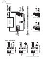
Test options
Telecommand
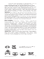
Replacement
Contact sales with the unit or the battery order code
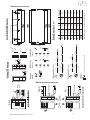
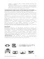
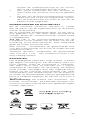
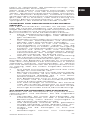
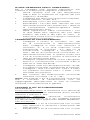
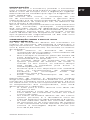
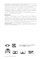
Fixing centers
4AA 100 (140) 30 (34) 15 (20) (125)
3Cs 130 (160) 25 (26) 25 (26) (150)
4Cs 173 (203) 25 (26) 25 (26) (193)
5Cs 215 (245) 25 (26) 25 (26) (235)
3D 182 (225) 34 (35) 34 (35) (210)
4D 242 (285) 34 (35) 34 (35) (270)
LifePo4 134 (173) 31 (32) 31 (32) (157)
Type L W H
Values inside parentheses refer to batteries with mounting caps.
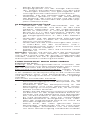
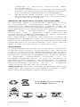
Self test sequence CGL+ @installation
Lamp
Battery
1 week +12h 1 week 1 week 1 week
1 week +12h @ EVEN
2 weeks +12h @ ODD
26 weeks 26 weeks
26 weeks 26 weeks
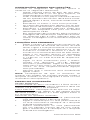
Self test sequence CGL+ @operation
Lamp
Battery
1 week 1 week 1 week
26 weeks @ EVEN
27 weeks @ ODD
CGL+, Bi-color LED
Test
Green:
Green:
Yellow:
Yellow:
2 sec
0,5 sec
(Green/Yellow)
DALI, Bi-color LED
Test
Green:
Green:
Red:
Red:
2 sec
0,5 sec
(Green/Red)
Self-contained,
Green:
Green:
Green LED
+7
days
×
×
ODD
EVEN
Indicating LED
6
4
5
3
1
2
8
7
LED
LED
6
4
5
3
1
2
8
7
LED
LED
Indicating LED
Wiring
Test options

5
www.eaton.com
CGL+
6
4
5
3
1
2
8
7
IN +
LED R
LED B
1h:
3h:
CV 12V:
CGLine+ Bus
OUT +
OUT -
IN -
Red
Brown
Indicating
Bicolor LED
CGL+
CGL+
6
4
5
3
1
2
8
7
IN +
LED Y
LED W
1h:
3h:
CV 12V:
DALI Bus
OUT +
OUT -
IN -
White
Yellow
DALI
Indicating
Bicolor LED
DALI
DALI
LE D
6
4
5
3
1
2
8
7
LED Y
LED W
TL B+
TL A-
IN -
OUT -
OUT +
IN +
-
+
9Vdc
Telecommand
6
4
5
3
1
2
8
7
LED Y
LED W
TL B+
TL A-
IN -
OUT -
OUT +
IN +
est by Normally Closed Switch
NC
Test options
6
4
5
3
1
2
8
7
IN +
LED
LED
1h:
3h:
CV 12V:
Bus
OUT +
OUT -
IN -
Brown/White
Red/Yellow
NC
CGL+/DALI
Indicating
Bicolor LED
6
4
5
3
1
2
8
7
LED Y
LED W
TL B+
TL A-
IN -
OUT -
OUT +
IN +
230Vac
-
+
9Vdc
Test by Telecommand
6
4
5
3
1
2
8
7
LED Y
LED W
TL B+
TL A-
IN -
OUT -
OUT +
IN +
230Vac
Test by Normally Closed Switch
6
4
5
3
1
2
8
7
LED Y
LED W
TL B+
TL A-
IN -
OUT -
OUT +
IN +
230Vac
Test by Normally Open Switch
NC
NO
6
4
5
3
1
2
8
7
LED Y
LED W
TL B+
TL A-
IN -
OUT -
OUT +
IN +
0Vac
Emergency to Rest by
Telecommand
Telecommand Signal
-
+
9Vdc
=
TL A-
TL B+
-
+
9Vdc
=
TL A-
TL B+
Emergency
6
4
5
3
1
2
8
7
LED Y
LED W
TL B+
TL A-
IN -
OUT -
OUT +
IN +
0Vac
Telecommand Signal
Rest
6
4
5
3
1
2
8
7
IN +
LED
LED
1h:
3h:
CV 12V:
Bus
OUT +
OUT -
IN -
Red/White
Brown/Yellow
NC
Test by Normally Closed Switch
CGL+/DALI
Indicating
Bicolor LED
Test options
Telecommand
Replacement
Contact sales with the unit or the battery order code
Fixing centers
4AA 100 (140) 30 (34) 15 (20) (125)
3Cs 130 (160) 25 (26) 25 (26) (150)
4Cs 173 (203) 25 (26) 25 (26) (193)
5Cs 215 (245) 25 (26) 25 (26) (235)
3D 182 (225) 34 (35) 34 (35) (210)
4D 242 (285) 34 (35) 34 (35) (270)
LifePo4 134 (173) 31 (32) 31 (32) (157)
Type L W H
Values inside parentheses refer to batteries with mounting caps.
Self test sequence CGL+ @installation
Lamp
Battery
1 week +12h 1 week 1 week 1 week
1 week +12h @ EVEN
2 weeks +12h @ ODD
26 weeks 26 weeks
26 weeks 26 weeks
Self test sequence CGL+ @operation
Lamp
Battery
1 week 1 week 1 week
26 weeks @ EVEN
27 weeks @ ODD
CGL+, Bi-color LED
Test
Green:
Green:
Yellow:
Yellow:
2 sec
0,5 sec
(Green/Yellow)
DALI, Bi-color LED
Test
Green:
Green:
Red:
Red:
2 sec
0,5 sec
(Green/Red)
Self-contained,
Green:
Green:
Green LED
+7
days
×
×
ODD
EVEN
Indicating LED
6
4
5
3
1
2
8
7
LED
LED
6
4
5
3
1
2
8
7
LED
LED
Indicating LED
Telecommand
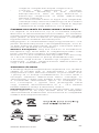
Dimensions
Battery Dimensions (in mm)
Conversion Kit LED Dimensions
Indicating LED messages

Conversion kit LED
6
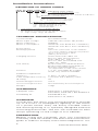
DEFINITION OF ORDER CODES:
Indicating LED Cable:
__ : having indicating LED only
TB: having indicating LED and NC Test Button
Remote connection:
_: Telecommand
CGL: Connection for CGL+ bus
D: Connection for DALI bus
Battery cell number / size:
4AA: NiCd AA/0.8Ah
xCS: NiCd CS/1.7Ah (3 or 4 or 5)
xD: NiCd VTD/4Ah (3 or 4)
2L: LiFePo4/3.2Ah
Converter output voltage range:
L: Low voltage range 3..33Vdc (SELV)
M: Medium voltage range 20..55Vdc (SELV)
H: High voltage range 40-180Vdc
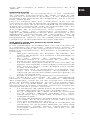
TECHNICAL SPECIFICATIONS:
System Mode Non-Maintained
Mains input voltage 230 V AC ±5% (218,5 - 241,5 V AC)
Mains frequency 50/60Hz
Mains Consumption 20mA AC max @ AA & L cell battery
30mA AC max @ CS & D cell battery
Power factor 0,47
Recharge period 24 hours / 16 hours on 2h variants
*on LiFePo variants charging temperature
range is between 0
o
C..50
o
C
(battery protection)
Charging monitor Green LED with cable 1m
Bi-color LED (Green/Yellow)
with cable 1m - CGL+
Bi-color LED (Green/Red) with
cable 1m - DALI
Test facility by Normally Closed Push button
by Normally Open Push button*
by Telecommand signal*
*not applicable on CGL+/DALI variants
Duration 1 or 3h, selectable by jumper,
2h/3h only variants available
Ambient temperature
range (t
a
) 5..40°C / 5..50°C (LiFePo)
Case temperature max (t
c
) converter: 60°C battery: 50°C
IP rating 20
Overheating protection 110°C
Short circuit protection Non-inherently short circuit proof
Weight 125gr
STANDARDS:
Complies with: EN 61347-1, EN 61347-2-7,
EN 55015, EN 61547, EN 61000-3-2
According to: EN 60598-2-22,
EN 61347-2-13, RoHS
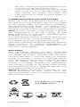
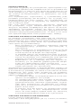
OVERVIEW
Conversion kits allow your existing tting to provide
up to 3 hours of emergency lighting in the event
of a power failure. They are easily installed within
the existing tting or in specially designed external
mounting enclosures. The kits are available for LED
lamps operating on the range of 3 to 180Vdc.
PREPARATION
Before using the converter, plan you conversion
carefully, read this leaet and follow the instructions
given in order to comply with current legislation. It is
Installation Instructions

7
www.eaton.com
EN
also recommended to follow the requirements of
ICEL 1004:2003.
In most cases, installation of a conversion kit will
invalidate the manufacturers guarantee and it is
the responsibility of the installer to comply with
the CE marking, Low Voltage and EMC directives.
If a previously installed light tting is to be
converted, any components showing signs
of degradation should be replaced. It is also
recommended that all internal wiring should be
renewed using high temperature (105°C) PVC
cable or the type originally specied if it has a
higher rating.
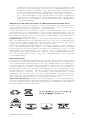
COMPONENT LAYOUT GUIDELINES
The conversion kits are best installed inside the
light tting, usually requiring the repositioning
of existing components (i.e. ballast and terminal
blocks). When installing inside the tting:
• Do not obstruct cable entries, mounting
facilities, lighting controllers or covers.
• Do not locate the batteries or capacitor near
excessive heat sources, e.g. ballasts and
lamp ends.
• The module should be placed as close as
possible to the ballast to keep wires short,
while being far enough away to prevent
overheating.
• Ensure your layout doesn’t interfere with
the essential safety features of the tting
such as shrouding, earthing etc.
• Avoid altering the tting’s normal lighting
distribution.
Space & temperature restrictions may require
remote mounting of the batteries or the complete
conversion kit in a special enclosure. If this
is necessary, it is not as important to take into
account the component temperatures but you
should note the following:
• The cable to the fully remote enclosure
must not exceed 2m.
• If mounted more than 1m from the light
tting, the remote enclosure must be
connected using re proof cable.
• Battery leads must be as short as possible,
and the total resistance of the battery lead
must not exceed 0,05 ohms.
• The indicating LED should be mounted
within the light tting or remote enclosure
where it is clearly visible during normal
operation (mounting requires 0.25” or
6,35mm hole).
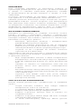
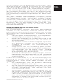
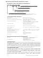
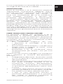
GENERAL WIRING GUIDELINES
Refer to the diagrams for typical wiring
connections and observe the following guidelines:
• Always use high temperature 105°C PVC
cable (or a higher grade if originally used in

Conversion kit LED
8
the light tting).
• All metal work within an earthed tting
MUST be securely earthed, including
reectors and louvers.
• Keep cables as short as possible.
• Mains wiring must exit tting from nearest
entry/exit point.
• Keep mains wiring away from the LED lamp
cables for better EMC performance.
• In SELV conversion applications keep
mains wiring separated from the battery,
LED lamp and indicating LED wiring or use
special (double insulated) wiring.
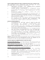
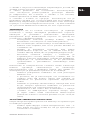
TERMINAL CONNECTIONS
• Connect the neutral to ‘N’ terminal of the
converter and to the mains LED driver neutral
input terminal. Connect the unswitched
live to terminal ‘L’ and the switched live in
terminal ‘L1 In’ on the converter. Connect
converter’s ‘L1 OUT’ terminal to the mains
LED driver live input terminal.
• Connect the yellow/white or red/brown LED
wire to the terminal marked ‘LED Y’/'LED
W' or 'LED R'/'LED B' respectively.
• Connect the two cables for the telelcommand
signal on the '-A'/'+B' terminal blocks
(polarity sensitive connection). Connect the
two cables from CGL+ or Dali bus on the
'CGL+' or 'Dali' terminal blocks respectively
(polarity free connection).
• Ensure the light tting is securely earthed
Note: Make sure that the terminals on the module
cannot be touched when changing the lamp or
starter by shrouding them with earthed metal or
thermoplastic insulation.
TESTING THE CONVERSION
Electrical Tests
Earth Continuity: Earth resistance between earth
terminal and all metal parts must be less than 0,5
ohms at 10 Amps.
Electrical Strength: Ensure that there is no
breakdown when use 1500V ac (50/60Hz) test
voltage between the Neutral and Live bonded
together and the Earth terminal.
Testing an Installed Fitting:
• Connect mains voltage to the unswitched
live supply and ensure that the LED is lit.
• Connect mains voltage to the switched and
unswitched live supplies and check that the
lamp lights correctly.
• Apply mains supply to the unswitched live
for a minimum of 10 min. Disconnect the
supply and check that the emergency lamp
lights.
• It is recommended that a full duration test is
carried out by applying the mains supply for

9
www.eaton.com
24 hours and ensuring the emergency lamp
operates for the specied duration.
• If any of the above tests fail, repeat them
after a full 24 hour recharge period and
then restore the supply and check the
LED indication to make sure the battery is
charging.
COMMISSIONING & ROUTINE TESTING
When you have completed the conversion, ll in
the date of commissioning in the space provided
on the battery label. The conversion invalidates
any certication (e.g, ENEC / CE safety mark),
therefore all markings must be removed and
replaced with the caution/warning labels supplied.
Note: It is the installer’s responsibility to ensure
the requirements of the CE marking, LV and
EMC directives are met. ICEL 1004:2003 gives
guidelines on this if required.
A routine testing scheme should be dened and
followed, to ensure correct emergency operation
of installed converted luminaries over time.
The types of testing and test frequencies dened,
must comply to any relevant requirements of
regulations and / or directives applicable to the
country of the installation.
BATTERIES
The recharging device provides reinforced
insulation, is protected against short circuit and
can charge the battery normally after the short
circuit is removed. It normally takes 10 minutes
charge to provide 1 minute of discharge power
from the battery. The battery should be replaced
with an original Eaton part when the rated
duration is no longer achieved. The replacement
part number is written on the battery label. Always
use the approved NiCd or LiFePO4 batteries and
store them between 0 and 25°C.
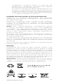
Warning: When disposing of batteries, do not
pierce, incinerate or short circuit them. The
approved batteries contain cadmium and must be
disposed of correctly.

Conversion kit LED
10
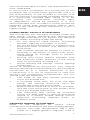
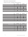
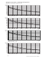
Electrical characteristics
Output Current / Voltage characteristics
Battery Cell Type
Battery Cell Number (Cell alignment)
Typical Charge Current (mA dc)
Duration (h)
Typical Output Power (W)
Typical Discharge Current (mA dc)
LED Lamp Voltage Range (V dc)
LED Lamp Max Capacitance (µF)
Constant Voltage (CV) output (V dc)
Open Voltage U-OUT (V dc)
NiCd AA 0,8Ah
4 (2x2)
40
NiCd Cs 1,7Ah
3 (3x1)
95
LVLD LVLD
1
1,75
440
3
0,65
180
1
2,75
950
3
1,1
390
3 ..33 3 ..33
1
12 12
- -
40 (SELV) 40 (SELV)
1
Battery Cell Type
Battery Cell Number (Cell alignment)
Typical Charge Current (mA dc)
Duration (h)
Typical Output Power (W)
Typical Discharge Current (mA dc)
LED Lamp Voltage Range (V dc)
LED Lamp Max Capacitance (µF)
Constant Voltage (CV) output (V dc)
Open Voltage U-OUT (V dc)
NiCd AA 0,8Ah
4 (2x2)
40
NiCd Cs 1,7Ah
4 (4x1)
90
MVLD MVLD
1
1,65
440
3
0,65
180
1
3,4
950
3
1,4
390
20 ..55 20 ..55
1
24 24
- -
60 (SELV) 60 (SELV)
1
Battery Cell Type
Battery Cell Number (Cell alignment)
Typical Charge Current (mA dc)
Duration (h)
Typical Output Power (W)
Typical Discharge Current (mA dc)
LED Lamp Voltage Range (V dc)
LED Lamp Max Capacitance (µF)
Constant Voltage (CV) output (V dc)
Open Voltage U-OUT (V dc)
NiCd AA 0,8Ah
4 (2x2)
40
NiCd Cs 1,7Ah
5 (5x1)
95
HVLD HVLD
1
1,55
440
3
0,6
180
41 ..175
1
4,1
950
3
1,65
390
40 ..180 4 ..180
1
48 48
- -
200 200
1

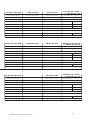
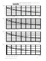
11
www.eaton.com
NiCd 4D 4Ah
4 (4x1)
180
2
5
1200
3 ..33
1
-
40 (SELV)
NiCd 3D 4Ah
3 (3x1)
180
3
2.75
950
3..33
1 1
-
40 (SELV)
NiCd 4D 4Ah
4 (4x1)
180
3
3,7
950
3 ..33
-
40 (SELV)
LVLD-3DLVLD-4D-TB LVLD-4D
LiFePo4 3,2Ah
2 (2x1)
220 (max)
1
6
1100
3
3
510
3 ..33
1
12
-
40 (SELV)
LVLD-2L-CGL
or LVLD-2L-D
NiCd 4D 4Ah
4 (4x1)
180
2
4,2
1200
20 ..55
1
-
60 (SELV)
NiCd 4D 4Ah
4 (4x1)
180
3
3,4
950
20 ..55
1
-
60 (SELV)
MVLD-4D-TB
NiCd 3D 4Ah
3 (3x1)
180
3
2,5
950
20 ..55
1
-
60 (SELV)
MVLD-3D MVLD-4D
LiFePo4 3,2Ah
2 (2x1)
220 (max)
1
4,8
950
3
2,4
450
20 ..55
1
24
-
60 (SELV)
MVLD-2L-CGL
or MVLD-2L-D
NiCd 4D 4Ah
4 (4x1)
180
2
4
1100
40 ..180
1
-
200
NiCd 4D 4Ah
4 (4x1)
180
3
3,1
40 ..180
1
-
200
HVLD-4D-TB HVLD-4D
LiFePo4 3,2Ah
2 (2x1)
220 (max)
1
4,2
850
3
2,2
450
40 ..180
1
48
-
200
HVLD-2L-CGL
or HVLD-2L-D

Conversion kit LED
12
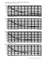
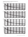
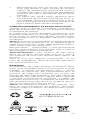
LVLD-3CS, 3h
LVLD-4AA, 3h
LVLD-4AA, 1h
LVLD-3CS, 1h
LVLD-3D, 3h
I
LED
[mA]I
LED
[mA]I
LED
[mA]I
LED
[mA]
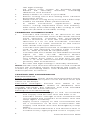
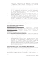
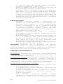
Output Current / Voltage diagrams
Low Voltage LED Driver
LVLD-2L-CGL, 1h
LVLD-2L-CGL, 3h
LVLD-4D, 3h
LVLD-4D-TB, 2h
LED current at nominal battery voltage and min.
battery dischanrge current
LED current at nominal battery voltage and max.
battery dischanrge current
I
LED
[mA]
I
LED
[mA]I
LED
[mA]
I
LED
[mA]
0
100
200
300
400
500
600
700
800
900
3 6 9 12 15 18 21 24 27 30 33
0
100
200
300
400
500
600
3 6 9 12 15 18 21 24 27 30 33
0
100
200
300
400
500
600
700
800
3 6 9 12 15 18 21 24 27 30 33
0
100
200
300
400
500
600
700
800
3 6 9 12 15 18 21 24 27 30 33

13
www.eaton.com
LVLD-3CS, 3h
LVLD-4AA, 3h
LVLD-4AA, 1h
LVLD-3CS, 1h
LVLD-3D, 3h
I
LED
[mA]I
LED
[mA]I
LED
[mA]I
LED
[mA]
LVLD-2L-CGL, 1h
LVLD-2L-CGL, 3h
LVLD-4D, 3h
LVLD-4D-TB, 2h
LED current at nominal battery voltage and min.
battery dischanrge current
LED current at nominal battery voltage and max.
battery dischanrge current
I
LED
[mA]
I
LED
[mA]I
LED
[mA]
I
LED
[mA]
0
100
200
300
400
500
600
700
800
900
3 6 9 12 15 18 21 24 27 30 33
0
100
200
300
400
500
600
3 6 9 12 15 18 21 24 27 30 33
0
100
200
300
400
500
600
700
800
3 6 9 12 15 18 21 24 27 30 33
0
100
200
300
400
500
600
700
800
3 6 9 12 15 18 21 24 27 30 33

Conversion kit LED
14
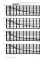
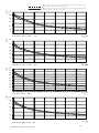
MVLD-4CS, 3h
MVLD-4CS, 1h
MVLD-4D, 3h
MVLD-4AA, 1h
MVLD-4AA, 3h
I
LED
[mA]I
LED
[mA]
I
LED
[mA]
I
LED
[mA]
0
20
40
60
80
100
120
140
160
180
200
20 25 30 35 40 45 50 55
MVLD-2L-CGL, 1h
MVLD-2L-CGL, 3h
MVLD-3D, 3h
MVLD-4D-TB, 2h
LED current at nominal battery voltage and min.
battery dischanrge current
LED current at nominal battery voltage and max.
battery dischanrge current
I
LED
[mA]I
LED
[mA]I
LED
[mA]
I
LED
[mA]
0
50
100
150
200
250
300
20 25 30 35 40 45 50 55
0
20
40
60
80
100
120
140
20 25 30 35 40 45 50 55
0
20
40
60
80
100
120
140
20 25 30 35 40 45 50 55
0
50
100
150
200
250
20 25 30 35 40 45 50 55
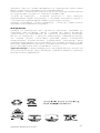
Output Current / Voltage diagrams
Medium Voltage LED Driver

15
www.eaton.com
MVLD-2L-CGL, 1h
MVLD-2L-CGL, 3h
MVLD-3D, 3h
MVLD-4D-TB, 2h
LED current at nominal battery voltage and min.
battery dischanrge current
LED current at nominal battery voltage and max.
battery dischanrge current
I
LED
[mA]I
LED
[mA]I
LED
[mA]
I
LED
[mA]
0
50
100
150
200
250
300
20 25 30 35 40 45 50 55
0
20
40
60
80
100
120
140
20 25 30 35 40 45 50 55
0
20
40
60
80
100
120
140
20 25 30 35 40 45 50 55
0
50
100
150
200
250
20 25 30 35 40 45 50 55

Conversion kit LED
16
HVLD-5CS, 3h
HVLD-4AA, 3h
HVLD-4AA, 1h
HVLD-5CS, 1h
I
LED
[mA]I
LED
[mA]I
LED
[mA]
I
LED
[mA]
Output Current / Voltage diagrams
High Voltage LED Driver
HVLD-2L-CGL, 1h
HVLD-2L-CGL, 3h
HVLD-4D, 3h
HVLD-4D-TB, 2h
LED current at nominal battery voltage and min.
battery dischanrge current
LED current at nominal battery voltage and max.
battery dischanrge current
I
LED
[mA]I
LED
[mA]I
LED
[mA]I
LED
[mA]
0
20
40
60
80
100
120
40 60 80 100 120 140 160 180
0
10
20
30
40
50
60
40 60 80 100 120 140 160 180
0
10
20
30
40
50
60
70
80
90
40 60 80 100 120 140 160 180
0
20
40
60
80
100
120
40 60 80 100 120 140 160 180

17
www.eaton.com
HVLD-2L-CGL, 1h
HVLD-2L-CGL, 3h
HVLD-4D, 3h
HVLD-4D-TB, 2h
LED current at nominal battery voltage and min.
battery dischanrge current
LED current at nominal battery voltage and max.
battery dischanrge current
I
LED
[mA]I
LED
[mA]I
LED
[mA]I
LED
[mA]
0
20
40
60
80
100
120
40 60 80 100 120 140 160 180
0
10
20
30
40
50
60
40 60 80 100 120 140 160 180
0
10
20
30
40
50
60
70
80
90
40 60 80 100 120 140 160 180
0
20
40
60
80
100
120
40 60 80 100 120 140 160 180

Conversion kit LED
18
DEFINIRANJE KATALOŠKIH BROJEVA
TEHNIČKE SPECIFIKACIJE:
Način rada pripravni spoj
Ulazni napon 230 V AC ±5% (218, 5 - 241,5 V AC)
Frekvencija 50/60Hz
Potrošnja energije 20mA AC max @ AA & L veličina baterije
30mA AC max @ CS & D veličina baterije
Faktor snage 0.47
Period ponovnog punjenja 24 sata / 16 sati na 2h varijanti
* Na LifePo varijanti dozvoljen raspon temperature
punjenja je između : 0°C…50°C ( zaštita baterije )
Kontrolna punjenja LED svetiljkom, sa kablom 1m
Dvobojna LED (Zeleno/Žuta) sa kablom
1m - CGL+
Dvobojna LED (Zeleno/Crvena) sa kablom
1m - DALI
Način testiranja Komandnim signalom*
Normalno zatvorenim tasterom
Normalno otvorenim tasterom*
*nije primjenjivo na CGL+/DALI varijante
Trajanje 1 ili 3h, odabir trajanja autonomije
pomoću kratkospojnika,
2h/3h samo raspoložive varijante
Radna temperatura (t
a
) 5..40°C / 5..50°C (LiFePo)
Maks. temperatura kućišta (t
c
) konvertor: 60°C / baterija: 50°C
IP stupanj zaštite 20
Zaštita od pregrijavanja 110°C
Zaštita od kratkog spoja ne inherentni dokaz kratkog spoja
Težina 125gr
STANDARDI:
U skladu sa: EN 61347-1, EN 61347-2-7,
EN 55015, EN 61547,
EN 61000-3-2
Certicirano prema: EN 60598-2-22,
EN 61347-2-13, RoHS
PREGLED
Komplet za konverziju omogućava da postojeću rasvjetu
pretvorite u rasvjetu za slučaj nužde autonomije do
3 sata u slučaju nestanka električne energije. Lako se
instalira u postojeća kućišta ili u specijalno dizajnirna
kućišta za vanjsku montažu. Kompleti su dostupni za LED
lampe radnog napona od 3 do 180 Vdc.
Uputstvo za Instalaciju
LED Kabl za indikaciju ukljućuje:
__ : posjeduje jedino LED indikaciju
TB: posjeduje LED indikaciju I NC Test taster
Spoj na daljinu:
_: Daljinsko
CGL: Priključak za CGL+ protokol
D: Priključak na DALI protokol
Broj / veličina ćelije baterije:
4AA: NiCd AA/0.8Ah
xCS: NiCd CS/1.7Ah (3 ili 4 ili 5)
xD: NiCd VTD/4Ah (3 ili 4)
2L: LiFePo4/3.2Ah
Izlazni naponski domet konvertora:
L: domet niskog napona 3..33Vdc (SELV)
M: domet srednjeg napona 20..55Vdc (SELV)
H: domet visokog napona 40-180Vdc

19
www.eaton.com
HR
PRIPREMA
Prije upotrebe kompleta za konverziju pažljivo ju
isplanirajte, pročitajte ovo uputstvo i pratite instrukcije
u skladu sa važećim zakonskim propisima. Takođe
je preporučljivo da pratite zahtjeve u skladu sa ICEL
1004:2003.
Garancija proizvođača je nevažeća ukoliko instalater
nije upoznat sa CE certifkatom I EMC direktivama.
Ukoliko planirate konverziju ranije instalirane rasvjete,
prethodno trebate izvršiti zamjenu svih komponenti
koji pokazuju bilo kakve znakove oštećenja. Također
se preporuča zamijeniti sve kablove kablovima visoke
podnošljive temperature (105°C) PVC ili kablovima
orginalno specificiranim ukoliko imaju veću zaštitu.
RASPORED KOMPONENTI
Komplet za konverziju je najbolje instalirati unutar
kućišta rasvjete i uglavnom zahtjeva razmještanje
postojećih komponenti. Kada instalirate unutar kućišta
nemojte remetiti ulaz kablova, opreme za montiranje,
kontrolera osvetljenja i pokriva:
• Nemojte postavljati baterije i kondenzatore
pored direktnog izvora topline.
• Modul bi trebalo pozicionirati što je moguće
bliže balastu kako bi žice bile što kraće, a ujedno
i dovoljno daleko kako bi spriječili pregrijavanje.
• Uvjerite se da raspored ne ometa osnovne
sigurnosne karakteristike.
Ograničenja po pitanju prostora i temperature mogu
zahtjevati izmještanje baterije i kompleta za konverziju
u specijalna kućišta:
• Nije neopohodno uzimati u obzir temperature
komponenti ali treba obratiti pažnju na slijedeće:
kabl do izdvojenog kučišta ne smije biti duži od
2m.
• Ukoliko se montira na udaljenost veću od 1m
kućište mora biti povezano vatrootpornim
kablom.
• Kontakti baterije moraju biti što je moguće kraći i
ukupna otpornost kontakata baterije ne sme biti
veća od 0,5 oma.
• Signalna LED dioda mora biti jasno vidljiva
tokom normalnog rada (montaža zahtjeva rupu
promjera 6,35mm).
UPUTSTVO ZA POVEZIVANJE
Pratite sheme povezivanja i pridržavajte se slijedećih
uputa:
• Uvijek koristite kablove koji mogu izdržati
temperaturu 105°C ili višu klasu.
• Svi metalni dijelovi MORAJU biti uzemljeni.
• Kablovi moraju biti što je moguće kraći.
• Kablovi napajanja moraju izaći iz kućišta na
najbližem izlazu.
• Kablove napajanja držati dalje od LED svetiljke
radi boljih EMC performansi.
• U SELV konverzijskoj aplikaciji držati glavno

Conversion kit LED
20
napajanje odvojeno od baterije, LED lampe
i indikacije LED lampe napajanja ili koristiti
specijalno dvostruko izolirano napajanje.
PRIKLJUČCI
• Povezati nulu na priključak N na konvertoru i na
priključak N na glavnom LED upravljaču. Povezati
direktnu fazu na priključak L a prekinutu fazu
na L1 priključak konvertora. Povezati priključak
L1 konvertorskog izlaza L1 OUT na glavni LED
upravljač ulazni priključak.
• Povežite žuti/bijeli ili crveni/smeđi LED žicu na
klemu identično označenu sa ‘LED Y’/'LED W' ili
'LED R'/'LED B'
• Povežite dva kabla za signal telekomande na
'-A'/'+B' priključne kleme (konekcija osjetljiva na
promjenu polariteta). Povežite dva kabla sa CGL+
ili DALI protokola na 'CGL+' ili 'Dali' priključne
kleme identično označene (konekcija neosjetljiva
na promjenu polariteta).
• Pobrinite se da je sigurno uzemljeno.
Napomena: pobrinite se da se priključci na modulima
ne mogu dodirnuti prilikom zamjene lampe ili startera
obavijajući ih izolacionim materijalom.
ISPITIVANJE KONVERZIJE
Električno testiranje
Neprekidnost uzemljenja: otpornost između
uzemljenog terminala i svih metalnih dijelova mora biti
manja od 0,5 oma na 10 A.
Električna snaga: pobrinite se da nema kvarova pri
1500VAC (50/60Hz) napona između N i L i priključka
uzemljenja.
Testiranje instaliranog osvjetljenja:
• Povežite napajanje i pobrinite se da LED indikator
svjetli. Povežite napajanje na rasvjetu i pobrinite
se da rasvjeta svjetli ispravno.
• Uključite napajanje minimum 10 minuta.
• Isključite napajanje i pobrinite se da lampa za
slučaj nužde svjetli.
• Preporučuje se izvesti test punog trajanja tako
što ćete ostaviti priključen napon 24 sata i nakon
skidanja sa napona lampa u slučaju nužde bi
trebala svjetliti naznačeni vremenski period.
• Ukoliko bilo koji test ne bude prošao u redu
ponovite ga poslije puna 24 sata punjenja i onda
obnovite napajanje i provjerite na LED indikatoru
da li se baterija puni.
PUŠTANJE U RAD I RUTINSKO TESTIRANJE
Kada ste završili konverziju upišite datum puštanja u rad
u prostor predviđen na naljepnici baterije.
Konverzija poništava sve certifikate (Kitemark /
CE), samim tim sve oznake moraju biti uklonjene i
zamijenjene natpisima Oprez/Upozorenje (Caution/
Warning) koje ste dobili u okviru isporuke.
Napomena: odgovornost instalatera je da osigura CE
La pagina sta caricando ...
La pagina sta caricando ...
La pagina sta caricando ...
La pagina sta caricando ...
La pagina sta caricando ...
La pagina sta caricando ...
La pagina sta caricando ...
La pagina sta caricando ...
La pagina sta caricando ...
La pagina sta caricando ...
La pagina sta caricando ...
La pagina sta caricando ...
La pagina sta caricando ...
La pagina sta caricando ...
La pagina sta caricando ...
La pagina sta caricando ...
La pagina sta caricando ...
La pagina sta caricando ...
La pagina sta caricando ...
La pagina sta caricando ...
La pagina sta caricando ...
La pagina sta caricando ...
La pagina sta caricando ...
La pagina sta caricando ...
La pagina sta caricando ...
La pagina sta caricando ...
La pagina sta caricando ...
La pagina sta caricando ...
La pagina sta caricando ...
La pagina sta caricando ...
La pagina sta caricando ...
La pagina sta caricando ...
La pagina sta caricando ...
La pagina sta caricando ...
La pagina sta caricando ...
La pagina sta caricando ...
La pagina sta caricando ...
La pagina sta caricando ...
La pagina sta caricando ...
La pagina sta caricando ...
La pagina sta caricando ...
La pagina sta caricando ...
La pagina sta caricando ...
La pagina sta caricando ...
La pagina sta caricando ...
La pagina sta caricando ...
La pagina sta caricando ...
La pagina sta caricando ...
La pagina sta caricando ...
La pagina sta caricando ...
La pagina sta caricando ...
La pagina sta caricando ...
-
 1
1
-
 2
2
-
 3
3
-
 4
4
-
 5
5
-
 6
6
-
 7
7
-
 8
8
-
 9
9
-
 10
10
-
 11
11
-
 12
12
-
 13
13
-
 14
14
-
 15
15
-
 16
16
-
 17
17
-
 18
18
-
 19
19
-
 20
20
-
 21
21
-
 22
22
-
 23
23
-
 24
24
-
 25
25
-
 26
26
-
 27
27
-
 28
28
-
 29
29
-
 30
30
-
 31
31
-
 32
32
-
 33
33
-
 34
34
-
 35
35
-
 36
36
-
 37
37
-
 38
38
-
 39
39
-
 40
40
-
 41
41
-
 42
42
-
 43
43
-
 44
44
-
 45
45
-
 46
46
-
 47
47
-
 48
48
-
 49
49
-
 50
50
-
 51
51
-
 52
52
-
 53
53
-
 54
54
-
 55
55
-
 56
56
-
 57
57
-
 58
58
-
 59
59
-
 60
60
-
 61
61
-
 62
62
-
 63
63
-
 64
64
-
 65
65
-
 66
66
-
 67
67
-
 68
68
-
 69
69
-
 70
70
-
 71
71
-
 72
72


Eaton HVLD-4D Installation Instructions Manual
- Tipo
- Installation Instructions Manual
in altre lingue
- English: Eaton HVLD-4D
- français: Eaton HVLD-4D
- español: Eaton HVLD-4D
- Deutsch: Eaton HVLD-4D
- Nederlands: Eaton HVLD-4D
- português: Eaton HVLD-4D
- čeština: Eaton HVLD-4D
- română: Eaton HVLD-4D
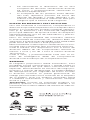
Documenti correlati
-
Eaton NexiTech NEXI1HIA-CGL Manuale utente
-
-
Eaton FlexiTech Exit Manuale del proprietario
-
-
-
-
Altri documenti
-
 Lumatek 600W Manuale utente
-
Hydrofarm Phantom II Digital Manuale utente
-
Sharp TADA - MP45S8443S00T2 Manuale del proprietario
-
 Thorn Chalice 3 / CHAL3 100 1400-840 HFIX E3D RSB Guida d'installazione
-
HELVAR 14xxD2 Control Panels Guida d'installazione
-
NightSearcher SA Titan Atex Linear Light Manuale utente
-
 Tridonic 28002681 Manuale utente
-
-
-
XTOOL F1 Manuale utente


