
Video Kit
Manuale installatore • Installation manual
LE11115AA01PC19W20
364613 - 364618- 364622

2
Attenzione: Le operazioni di installazione, configurazione, messa in servizio e manutenzione devono
essere effettuate da personale qualificato.
Caution: Installation, configuration, starting-up and maintenance must be performed by qualified
personnel
Attention: Les opérations d’installation, de configuration, de mise en service et d’entretien doivent
être confiées à un personnel qualifié.
Achtung: Die Installation, Konfiguration, Inbetriebnahme und Wartung dürfen nur von qualifizierten
Fachleuten vorgenommen werden
Atención: Las operaciones de instalación, configuración, puesta en servicio y mantenimiento han de
ser efectuadas por personal cualificado
Opgelet: Laat de installatie, de configuratie, de inbedrijfstelling en het onderhoud door gekwalificeerd
personeel verrichten
Atenção: As operações de instalação, configuração, colocação em serviço e manutenção devem ser
realizadas por pessoal qualificado

Video - Kit
3
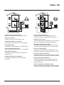
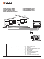
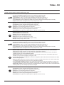
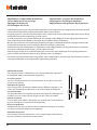
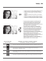
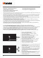
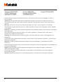
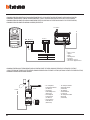
• Vecchio impianto a campanello
Impianto esistente con 3 fili e sola chiamata.
• Old system with bell
Existing system with 3 wires and just call.
• Ancienne installation a sonnette
Installation existante à 3 fils et un seul appel.
• Alte klingelanlage
Vorhandene 3-Leiter Anlage nur mit Ruffunktion.
• Vieja instalación con timbre
Instalación existente con 3 hilos y una llamada.
• Oude deurbelinstallatie
Bestaande 3-aderige installatie met alleen een
oproepfunctie.
• Antiga instalação em campaínha
Instalação existente com 3 fios e somente
chamada.
230 Vac 12 V
230 Vac
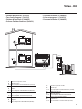
• Nuovo impianto citofonico
Impianto realizzato senza modifiche ai 2 fili
esistenti: chiamata, videocitofono e serratura.
• New door entry system
System made without modifications to the 2 existing
wires; call, video handset and electric door lock.
• Nouvelle installation phonique
Installation réalisée sans modifications sur les 2 fils
existants: appel, vidéophone, et serrure électrique.
• Neue haustelefonanlage
Anlage ohne Änderungen an den vorhandenen 2 Leiter:
Ruffunktion, Gegensprechanlage und elektrisches Schloss.
• Nueva instalación interfónica
Instalación realizada sin las modificaciones a los 2 hilos
existentes: llamada, videoportero y cerradura eléctrica.
• Nieuwe deurtelefooninstallatie
Installatie aangelegd zonder wijzigingen aan de
2 bestaande aders: oproep, beeldhuistelefoon en
elektrisch deurslot.
• Nova instalação do intercomunicador
Instalação realizada sem modificar os 2 fios existentes:
chamada, intercomunicador vídeo e fechadura eléctrica.
230 Vac 12 V
230 Vac

4
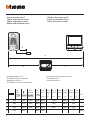
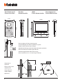
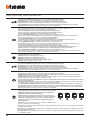
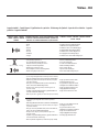
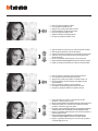
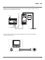
• Cavi e distanze (mm
2
)
• Cables and distances (mm
2
)
• Câbles et distances (mm
2
)
• Kabeln und Abstände (mm
2
)
• Cables y distancias (mm
2
)
• Kabels en afstanden (mm
2
)
• Cabos e distâncias (mm
2
)
B C
A
D
• Installazione no a 3 PI
• Installation of up to 3 handsets
• Montage jusqu’à 3 PI
• Installation von bis zu 3 Türstationen
• Instalación con un máximo de 3 PI
• Installatie tot 3 PI
• Instalação até 3 UI
>0,2 mm
2
BTicino
L4669
0,35 mm
2
0,28 mm
2
BTicino
C9881U/5E
AWG24 UTP5
BTicino
336904
One PTT
278 TP
0,28 mm
2
OneSYT
+ Digital
TP
5/10
OneSYT
+ Num TP
5/10
GIGA TW
CAT5E
AWG24
One SYT
+ Num TP
8/10
Cable
ARB.6060-1
6/10
Cable
EV6R
6/10
1
mm
2
A 50 m 140 m 150 m 200 m 200 m 145 m 200 m 50 m –
B 50 m 115 m 80 m 200 m 115 m 80 m 200 m 50 m –
C 50 m 130 m 80 m 200 m 100 m 80 m 200 m 50 m –
D 30 m 30 m – 50 m 30 m – – – 100 m

Video - Kit
5
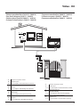
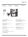
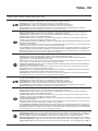
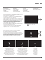
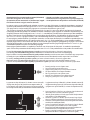
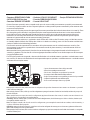
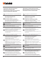
• A Pulsante locale apertura serratura.
B Chiamata al piano.
S+ S- 18 V; 4 A impulsivi. 250 mA mantenimento (30 Ω max).
• A Door lock release local pushbutton.
B Floor call.
S+ S- 18 V; 4 A impulsive. 250 mA holding current (30 Ω max).
• A Bouton local ouverture serrure.
B Appel à l’étage.
S+ S- 18 V; 4 A impulsifs. 250 mA entretien (30 Ω max).
• A Lokale Schlossöffnungstaste.
B Etagenruf.
S+ S- 18 V; 4 A impulsstrom. 250 mA Haltestrom (30 Ω max).
• A Pulsador local apertura cerradura.
B Llamada al piso.
S+ S- 18 V; 4 A por impulsos. 250 mA mantenimiento (30 Ω max).
• A Lokale knop opening slot.
B Oproep aan verdieping.
S+ S- 18 V; 4 A impulsief; 250 mA onderhoud (30 Ω max).
• A Botão local de abertura da fechadura.
B Chamada ao piso.
S+ S- 18 V; 4 A instantâneos. 250 mA continuos (30 Ω max).
•
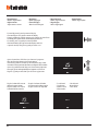
Schema monofamiliare (364613 - 364618)
•
One-family diagram (364613 - 364618)
•
Schéma mono-familial (364613 - 364618)
•
Schema Einfamilienhaus (364613 - 364618)
•
Esquema monofamiliar (364613 - 364618)
•
Schema eensgezins (364613 - 364618)
•
Esquema monofamiliar (364613 - 364618)
N
= –
= –
T = –
S = –
P
= –
–
=
B
P
= –
= –
= –
M
N
= –
= –
=
BUS
PL S+
S-
A
OFF ON
BUS

6
N
= –
= –
T = –
S = –
P
= –
–
=
P
= –
= –
= –
M
N
= –
=
=
*1
B
OFF ON
BUS
P
= –
= –
= –
M
N
= –
=
=
B
OFF ON
BUS
–
BUS
PL S+
S-
A
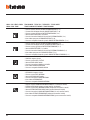
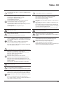
• Schema bifamiliare (364622)
• Two-family diagram (364622)
• Schéma bi-familiale (364622)
• Schema Zweifamilienhaus (364622)
• Esquema bifamiliar (364622)
• Schema tweegezins (364622)
• Esquema bifamiliar (364622)
• A Pulsante locale apertura serratura.
B Chiamata al piano.
S+ S- 18 V; 4 A impulsivi. 250 mA mantenimento (30 Ω max).
• A Door lock release local pushbutton.
B Floor call.
S+ S- 18 V; 4 A impulsive. 250 mA holding current (30 Ω max).
• A Bouton local ouverture serrure.
B Appel à l’étage.
S+ S- 18 V; 4 A impulsifs. 250 mA entretien (30 Ω max).
• A Lokale Schlossöffnungstaste.
B Etagenruf.
S+ S- 18 V; 4 A impulsstrom. 250 mA Haltestrom (30 Ω max).
• A Pulsador local apertura cerradura.
B Llamada al piso.
S+ S- 18 V; 4 A por impulsos. 250 mA mantenimiento (30 Ω max).
• A Lokale knop opening slot.
B Oproep aan verdieping.
S+ S- 18 V; 4 A impulsief; 250 mA onderhoud (30 Ω max).
• A Botão local de abertura da fechadura.
B Chamada ao piso.
S+ S- 18 V; 4 A instantâneos. 250 mA continuos (30 Ω max).

Video - Kit
7
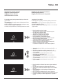
• Schema bifamiliare 2 (364622)
• Two-family diagram 2 (364622)
• Schéma bi-familiale 2 (364622)
• Schema Zweifamilienhaus 2 (364622)
• Esquema bifamiliar 2 (364622)
• Schema tweegezins 2 (364622)
• Esquema bifamiliar 2 (364622)
N
= –
= –
T = –
S = –
P
= –
–
=
B
BUS
P
= –
= –
= –
M
N
= –
=
=
–
OFF ON
B
BUS
P
= –
= –
= –
M
N
= –
=
=
*1
OFF ON
BUS
PL S+
S-
A
• A Pulsante locale apertura serratura.
B Chiamata al piano.
S+ S- 18 V; 4 A impulsivi. 250 mA mantenimento (30 Ω max).
• A Door lock release local pushbutton.
B Floor call.
S+ S- 18 V; 4 A impulsive. 250 mA holding current (30 Ω max).
• A Bouton local ouverture serrure.
B Appel à l’étage.
S+ S- 18 V; 4 A impulsifs. 250 mA entretien (30 Ω max).
• A Lokale Schlossöffnungstaste.
B Etagenruf.
S+ S- 18 V; 4 A impulsstrom. 250 mA Haltestrom (30 Ω max).
• A Pulsador local apertura cerradura.
B Llamada al piso.
S+ S- 18 V; 4 A por impulsos. 250 mA mantenimiento (30 Ω max).
• A Lokale knop opening slot.
B Oproep aan verdieping.
S+ S- 18 V; 4 A impulsief; 250 mA onderhoud (30 Ω max).
• A Botão local de abertura da fechadura.
B Chamada ao piso.
S+ S- 18 V; 4 A instantâneos. 250 mA continuos (30 Ω max).

8
• Dati dimensionali
• Dimensional data
• Données
dimensionnelles
• Maße
• Datos dimensionales
• Formaatgegevens
• Dados dimensionais
• Altezza consigliata salvo diversa normativa vigente.
• Recommended height, unless different regulations are specified.
• Hauteur conseillée sauf autre norme en vigueur.
• Empfohlene Höhe falls die gesetzlichen Vorschriften nichts anderes vorschreiben.
• Altura recomendada salvo normativa vigente diferente.
• Aanbevolen hoogte behoudens andere normen in voege.
• Altura aconselhada a não ser se a norma em vigor for diferente.
160 – 165 cm
135 – 140 cm
164 mm
165 mm
20,5 mm
176 mm
98 mm
31 mm
• Campo di ripresa
• Field of view
• Éclairage cadrage caméra
• Aufnahmebereich
• Campo de filmación
• Campo de filmagem
• Opnameveld
50 cm
105 cm
60 cm
50cm
160 cm

Video - Kit
9
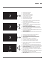
• Posto esterno
• Entrance panel
• Poste extérieur
• Türstation
• Placa exterior
• Externe plaats
• Unidade externa
1. Réglage du volume
Activation/désactivation tonalité de conrmation
ouverture serrure
2. Logement congurateurs
1. Adjustment volume
2. Enabling/disabling of door lock opening
conrmation tone
3. Congurator seat
1. Einstellung der Lautstärke
2. Aktivierung/Deaktivierung des Bestätigungssignals
nach erfolgter Türönung
3. Sitz der Konguratoren.
1. Regolazione del volume
2. Abilitazione/disabilitazione tono conferma
apertura serratura
3. Sede conguratori
1. Regulação do volume
2. Activação/desactivação do sinal de
conrmação da abertura da fechadura
3. Alojamento congurador
1. Regulación del volumen
2. Habilitación/deshabilitación del tono de
conrmación de apertura de la cerradura
3. Alojamiento conguradores
1. De geluidssterkte regelen
2. Activering/desactivering toon bevestiging
opening slot
3. Plaats van de conguratiemodules
ON OFF
ON OFF
1
3
2

10
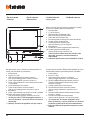
• Posto interno
• Handset
• Poste interne
• Hausstation
• Unidad interior
• Intern punt
• Unidade interna
Alla pressione i tasti si illuminano ed emettono un
“beep” (disattivabile da procedura).
1. Altoparlante
2. Display 5” (16:9)
3. LED segnalazione esclusione suoneria
LED rosso lampeggiante: suoneria esclusa
4. Tasto a soramento apertura serratura *
5. Tasto a soramento per attivazione posto estero
/ ciclamento
6. Guide tattili per non vedenti
7. Tasto disattivazione comunicazione
LED rosso lampeggiante: chiamata in corso
8. Microfono
9. Tasto a soramento comando luci scale / preferiti
10. Tasto attivazione comunicazione
LED verde lampeggiante: chiamata in arrivo
* Se alla pressione, i LED lampeggiano bianco, è
attiva la funzione "serratura sicura" ed il tasto è
disattivato.
* * Teleloop funzione disponibile solo per 364618
À la pression, les touches s’illuminent et émettent un «bip»
(désactivable à travers la procédure prévue à cet eet).
1. Haut-parleur
2. Écran 5” (16:9)
3. Voyant de signal exclusion sonnerie
Voyant rouge clignotant : sonnerie exclue
4. Touche à eeurement d’ouverture serrure (*)
Touche à eeurement d’activation poste
externe/cyclage
5. Guides tactiles pour non-voyants
6. Touche désactivation communication
Voyant rouge clignotant : appel en cours
7. Micro
8. Touche à eeurement commande lumières
escaliers / favoris
9. Touche activation communication
Voyant vert clignotant : arrivée d’un appel
* Si, à la pression, les voyants clignotent sur le
blanc, la fonction «serrure sécurisée» est active et
la touche est désactivée.ed il tasto è disattivato.
* * Fonction Téléloop disponible uniquement pour
364618
When pressed, the keys light up and emit a “beep”
(that can be deactivated by procedure).
1. Loudspeaker
2. 5” (16:9) display
3. Bell exclusion notication LED
Red LED ashing: bell excluded
4. Door lock release touch key *
5. Entrance panel/scrolling activation touch key
6. Tactile guides for the blinds
7. Communication enabling key
Red LED ashing: call in progress
8. Microphone
9. Favourites/staircase light control touch key
10. Communication enabling key
Green LED ashing: incoming cal
* If the LEDs flash white when pressed, the “safe
door lock” function is active and the key is
deactivated.
* * Inductive loop function only available for 364618
2
7
3
5
4*
8
6
1
10 9* *

Video - Kit
11
Bei Betätigung leuchten die Tasten auf und geben
einen "Piepton" ab (kann durch eine Prozedur
deaktiviert werden.)
1. Lautsprecher
2. Display 5” (16 : 9)
3. LED- Meldung Läutwerk ausgeschlossen
Rote LED blinkt: Läutwerk ausgeschlossen
4. Berührungstaste Schlossöner*
5. Berührungstaste zum Aktivieren der Türstation
und Taktieren
6. Taktile Hilfe für Sehbehinderte
7. Taste zur Deaktivierung der Kommunikation
Rote LED blinkt: Anruf im Gang
8. Mikrophon
9. Berührungstaste Treppenlicht / Favoriten
10. Taste zur Aktivierung der Kommunikation
Grüne LED blinkt: eintreen eines Anrufs
* Wenn die LEDs beim Drücken weiß blinken, ist
die Funktion „Schloss-Sicherheit“ aktiv und die
Taste ist deaktiviert.
* * Die Teleloop-Funktion ist nur für 364618 verfügbar
Con la presión, los botones se iluminan y emiten un
“beep” (desactivable según el procedimiento.)
1. Altavoz
2. Pantalla 5” (16:9)
3. LED de señalización de exclusión timbre
LED rojo parpadeante: timbre excluido
4. Botón de membrana apertura cerradura*
5. Botón de membrana para activación placa de
exterior / vista cíclica
6. Guías táctiles para invidentes
7. Botón desactivación comunicación
LED rojo parpadeante: llamada corriente
8. Micrófono
9. Botón de membrana para accionamiento de
luces escaleras / favoritos
10. Botón activación comunicación
LED verde parpadeante: llamada entrante
* Si con la presión, los LEDs parpadean en color
blanco, se activa la función "cerradura segura" y
el botón se desactiva.
* * Función Teleloop disponible solamente para
364618
De toetsen gaan branden en laten een “piep” (kan
met de procedure gedeactiveerd worden) horen
wanneer erop gedrukt wordt.
1. Luidspreker
2. Display 5” (16:9)
3. Led melding uitsluiting beltoon
Rode led knippert : beltoon uitgesloten
4. Touch-toetsen slotontgrendeling*
5. Touch-toets voor activering buitenpost/cyclische
weergave
6. Tastgeleiders voor blinden
7. Toets deactivering communicatie
Rode led knippert : lopende oproep
8. Microfoon
9. Touch-toets traphuisverlichting / favorieten
10. Toets activering communicatie
Groen led knippert: binnenkomende oproep
* De functie “veilig slot” is geactiveerd en de
toets is gedeactiveerd als de witte leds knip-
peren wanneer op de toets gedrukt wordt.
* * De Teleloop-functie is uitsluitend beschikbaar
voor 364618
Ao carregar as teclas iluminam-se e emitem um “bip”
(pode ser desativado através de procedimento.)
1. Altifalante
2. Ecrã 5” (16:9)
3. LED de sinalização de exclusão da campainha
LED vermelho intermitente: campainha excluída
4. Tecla de toque abertura da fechadura *
5. Tecla de toque para ativação unidade externa /
ativação cíclica
6. Guias táteis para não videntes
7. Tecla de desactivado de comunicação
LED vermelho intermitente: chamada em
andamento
8. Microfone
9. Tecla de toque de comando luzes das escadas/
favoritos
10. Tecla de ativação de comunicação
LED verde intermitente: chamada em chegada
* Se ao carregar, os LED piscam em branco,
está ativa a "fechadura segura" e a tecla é
desativada.
* * Função Teleloop disponível apenas para 364618

12
1. Micro-interrupteur pour fonction Slave/Master
2. Microinterrupteur ON/OFF fonction «serrure
sécurisée». ON=
Activer la fonction avec le dispositif non
alimenté
3. Logement des configurateurs.
4. Microinterrupteur ON / OFF de fin de ligne.
5. Bornes de branchement au BUS SCS 2 fils
6. Bornes de branchement d’un bouton externe
d’appel à l’étage
P
M
N
BUS
ON
OFF
MasterSlave
ON
CTS
1
2
BTICINO
V.le Borri, 231
21100 (VA) ITALY
Made in Italy
7. Joystick pour réglages et programmations
1. Slave / Master function microswitch
2. Line termination ON / OFF micro-switch.
ON=
To activate the function with device not
powered
3. Configurator socket
4. Line termination ON / OFF micro-switch.
5. 2 wires SCS BUS connection clamps.
6. Clamps for the connection of an external call to
the floor pushbutton
P
M
N
BUS
ON
OFF
MasterSlave
ON
CTS
1
2
BTICINO
V.le Borri, 231
21100 (VA) ITALY
Made in Italy
7. Joystick for adjustments and programming
1. Microinterruttore per funzione Slave / Master
2. Microinterruttore ON / OFF funzione “serratura
sicura”. ON=
Attivare la funzione con dispositivo non
alimentato
3. Sede dei configuratori
4. Microinterruttore ON / OFF di terminazione di tratta
5. Morsetti per il collegamento al BUS SCS 2 FILI
6. Morsetti per il collegamento di un pulsante
esterno di chiamata al piano
P
M
N
BUS
ON
OFF
MasterSlave
ON
CTS
1
2
BTICINO
V.le Borri, 231
21100 (VA) ITALY
Made in Italy
7. Joystick per regolazioni e programmazioni
• Posto interno
• Handset
• Poste interne
• Hausstation
• Unidad interior
• Intern punt
• Unidade interna
1. Mikroschalter für die Funktion Slave / Master
2. Mikroschalter ON / OFF für die Funktion „Schloss-
Sicherheit“ ON=
Die Funktion mit stromloser Vorrichtung
aktivieren
3. Sitz der Konfiguratoren.
4. Mikroschalter ON / OFF am Ende der Strecke.
5. Klemmen zum Anschluss an BUS, SCS, 2-Draht
6. Klemmen zum Anschluss an eine externe
Etagenruftaste
7. Joystick für Regelung und Programmierung
P
M
N
BUS
ON
OFF
MasterSlave
ON
CTS
1
2
BTICINO
V.le Borri, 231
21100 (VA) ITALY
Made in Italy
45 6 7
1
3
2

Video - Kit
13
1. Microinterruptor para función Slave / Master
2. Microinterruptor ON / OFF función "cerradura
segura". ON=
Activar la función con dispositivo no
alimentado
3. Alojamiento de los configuradores.
4. Microinterruptor ON / OFF final de tramo.
5. Bornes para la conexión al BUS SCS 2 hilos
6. Bornes para la conexión de un pulsador externo
de llamada a la planta
P
M
N
BUS
ON
OFF
MasterSlave
ON
CTS
1
2
BTICINO
V.le Borri, 231
21100 (VA) ITALY
Made in Italy
7. Joystick para regulaciones y programaciones
1. Microinterruptor para função Slave / Master
2. Microinterruptor ON / OFF função “fechadura
segura”. ON=
Ativar a função com dispositivo não alimentado
3. Sede dos configuradores.
4. Micro-interruptor ON / OFF de terminação do
segmento.
5. Bornes para a conexão ao BUS SCS DE 2 fios.
6. Bornes para a conexão de um botão externo de
chamada no piso
P
M
N
BUS
ON
OFF
MasterSlave
ON
CTS
1
2
BTICINO
V.le Borri, 231
21100 (VA) ITALY
Made in Italy
7. Joystick para regulações e programações
1. Microschakelaar voor Slave-/Master-functie
2. Microschakelaar ON / OFF functie “veilig slot”.
ON=
Activeer de functie wanneer het
apparaat niet wordt gevoed
3. Plaats van de configuratoren.
4. Microschakelaar ON / OFF voor de afsluiting van
het traject.
5. Aansluitklemmen voor de verbinding met de SCS
2-Draads BUS
6. Aansluitklemmen voor de verbinding van een
externe knop op de verdieping
P
M
N
BUS
ON
OFF
MasterSlave
ON
CTS
1
2
BTICINO
V.le Borri, 231
21100 (VA) ITALY
Made in Italy
7. Joystick voor regelingen en programmeringen

14
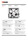
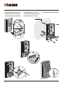
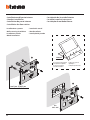
• Installazione posto esterno
• Entrance panel installation
•
Installation du poste extérieur
• Installation der Türstation
•
Instalación de la placa exterior
• Installatie externe plaats
•
Instalação da unidade externa
Ø 5 mm (max)
3
1
2
4
°
°
°
°
5
6
7

Video - Kit
15
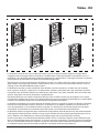
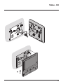
CLAC
1
CLAC
4
CLAC
2
CLAC
5
CLAC
3
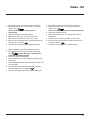
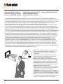
• La telecamera non deve essere installata di fronte a grandi sorgenti luminose, oppure in luoghi dove il
soggetto ripreso rimanga molto in controluce. Le telecamere a colori presentano, in condizioni di scarsa
luminosità, una sensibilità inferiore rispetto alle telecamere in bianco/nero. Si consiglia pertanto, in ambienti
poco illuminati di prevedere una fonte di illuminazione aggiuntiva.
• The camera must not be installed in front of large light sources, or in places where the subject viewed remains in
deep shadow. In poor lighting conditions colour cameras are less sensitive than black/white cameras. An extra
lighting source should be added in poorly lit rooms.
• La télécaméra ne doit pas être installée en face de fortes sources lumineuses, ou bien dans des endroits
où le sujet pris reste très à contre-jour. Les télécaméras couleurs présentent, dans des conditions de faible
luminosité, une sensibilité inférieure aux télécaméras noir/blanc. Il est donc conseillé, dans des milieux peu
éclairés, de prévoir une source de lumière supplémentaire.
• Die Kamera darf nicht vor starken Lichtquellen oder an Orten installiert werden, wo das Subjekt sich im Gegen-
licht befindet. Farbkameras besitzen bei schlechter Beleuchtung eine geringere Empfindlichkeit als Schwarz/Weiß
Kameras. Wir empfehlen daher eine zusätzliche Beleuchtungsquelle vorzusehen.
• La telecámara no debe ser instalada delante de fuentes luminosas grande en lugares en donde el individuo
filmado se encuentre demasiado en contraluz. Las telecámaras en colores presentan, en condiciones de
escasa luminosidad, una sensibilidad inferior respecto a las telecámaras en blanco/negro. Por lo tanto es
aconsejable en ambientes escasamente iluminados prever una fuente de iluminación extra.
• Installeer de camera niet tegenover grote lichtbronnen of op plaatsen waar de opname van het onderwerp door
sterk tegenlicht wordt gestoord. Camera’s met zijn bij een zwakke verlichting minder gevoelig dan zwart-wit ca-
mera’s. Daarom is het raadzaam om zwak verlichte omgevingen van extra verlichting te voorzien.
• A câmara não deve ser montada diante de fortes fontes de luz, ou então em lugares onde o elemento que
deve ser filmado fique muito em contraluz. As câmaras em cores apresentam, quando há pouca luminosida-
de, uma sensibilidade inferior em relação às câmaras em branco e preto. Portanto, recomenda-se, quando
os ambientes forem pouco iluminados providenciar uma fonte de iluminação adicional.

16
• Se si manifestasse il disturbo del fischio, (effetto Larsen), ridurre prima la potenza del microfono
, agendo con un cacciavite sul potenziometro corrispondente, fino ad un livello accettabile. Qualora il
fenomeno persista, agire sul potenziometro dell’altoparlante in modo da eliminare l’inconveniente.
Se il volume è troppo basso, aumentare prima il volume dell’altoparlante ed eventualmente anche quello
del microfono, tenendo presente che è preferibile una trasmissione chiara e priva di disturbi, che una al
limite dell’innesco (Larsen).
• In case of a whistle (Larsen effect), first reduce the microphones
power, adjusting the corresponding potenti-
ometers with a screw driver, until an acceptable level is reached. Should the whistle persist, adjust the loudspeakers
volume in order to eliminate the trouble. If the volume is too low level then, increase first the potentiometer of
the loudspeaker and secondly the one for the microphone, bearing in mind that a clear and noise free reception is
preferable than one just before whistling (Larsen).
• Lors de sifflement (effet de Larsen), reduire d’abord la puissance du micro
sur le potentiomètre corres-
pondant, à l’aide d’un tournevis, jusqu’à l’obtention d’un niveau satisfaisant. Si le sifflement persiste, régler
le potentiomètre du hautparleur jusqu’à l’élimination de celui-ci. Si le volume est trop bas, augmenter
d’abord la puissance du haut-parleur et éventuellement celle du micro, en considérant qu’une réception
claire et sans parasite est préférable à une communication à la limite de l’accrochage (effet de Larsen).
• Beim etwaigen Auftreten eines Pfeiftones (Larsen-Effekt), zuerst die Lautstärke des Mikrophones
bis auf einen
annehmbaren Wert herabsetzen, indem man das entsprechende Potentiometer mit einem Schraubendreher ein-
stellt. Sollte die Störung weiterhin bestehen, dann das Potentiometer des Lautsprechers bis zur Beseitigung des
Pfeiftones einstellen. Ist die Lautstärke nun zu niedrig, dann zuerst die des Lautsprechers und erst danach evtl. auch
die des Mikrophones erhohen, wobei ein deutlicher und störungsfreier Empfang einem an der Störungsgrenze lie-
gendem (Larsen-Effekt) vorzuziehen ist.
• Si se manifesta el silbido de acoplamiento, (efecto Larsen), reducir primero la potencia del micrófono
, girando con un destornillador el potenciómetro correspondiente, hasta obtener un nivel aceptable. Si el
fenómeno persistiera, regular el potenciómetro del altavoz hasta eliminar la interferencia. Si el volumen
es demasiado bajo, aumentar primero el volumen del altavoz y eventualmente también el del micrófono,
teniendo en cuenta que es preferible una transmissión clara y limpia de interferencias, que una al limite del
acoplo (Larsen).
• Als er een fluittoon hoorbaar is (effect van Larsen): verminder eerst het vermogen van de microfoon
met behulp
van een schroevendraaier zijn stroomregelaar zo te regelen dat de geluidssterkte van het gefluit aanvaardbaar
is. Als het verschijnsel niet verdwijnt, dan moet u ook de stroomregelaar van de luidspreker bijstellen. Als de
geluidssterkte nu te klein is, verhoog dan eerst de geluidssterkte van de luidspreker en daarna eventueel ook die
van de microfoon, en denk er bij het bijstellen aan dat een duidelijk hoorbaar en ongestoord geluid beter is dan een
harder geluid op de grens van het Larsen effect.
• Se se manifestar uma interferência no som (efeito de Larsen), começar por diminuir a potência do microfone
, rodando o potenciómetro correspondente com uma chave de parafusos, até obter um nível aceitável.
Se o fenómeno persistir, regular o potenciómetro do altifalante de modo a eliminar o problema. Se o
volume estiver demasiado baixo, começar por aumentar o volume do altifalante e depois, se necessário,
o do microfone, tendo presente que é melhor ter uma transmissão clara e sem interferências, que uma no
limiar de início de efeitos Larsen.

Video - Kit
17
• Configurazione posto esterno
• Entrance panel configuration
• Configuration poste extérieur
• Konfiguration Türstation
• Configuración placa exterior
• Configuratie externe plaats
•
Configuração unidade externa
– 1 2 3 4 5 6 7
4 s 1 s 2 s 3 s
*
6 s 8 s 10 s
*
Funzionamento come pulsante per max. 10 sec. dopodichè entra in stand-by.
Per estendere tale funzionamento oltre i 10 sec. utilizzare l’attuatore
346210 configurato con MOD=5.
* Operation as pushbutton for 10 sec. max after which it goes in stand-by.
In order to extend this type of operation over 10 seconds, use the actuator,
item 346210 configured with MOD=5.
* Fonctionnement comme bouton pendant 10 sec. max., ensuite passe
en stand-by. Pour étendre ce fonctionnement au-delà de 10 sec.,
utiliser l’actionneur 346210 configuré sur MOD=5.
* Die Tastenfunktion dauert max. 10 sec.; danach schaltet sie auf Standby.
Um diese Funktion zu verlängern und mehr als 10 sec. dauern zu lassen, den
Aktor 346210 verwenden und mit MOD=5 konfigurieren.
* Funcionamiento como pulsador durante al máx.10 s. después se pone
en standby. Para ampliar dicho funcionamiento a más de 10 s., use el
actuador art. 346210 configurado con MOD = 5.
* 10 sec. lange werking als knop, vervolgens vindt de overschakeling naar
stand-by plaats. Laat deze functie langer dan 10 sec. duren met behulp
van de actuator 346210 die als MOD=5 is geconfigureerd.
* Funcionamento como botão por um máximo de 10 segundos, depois
disto dispõe-se em standby. Para prolongar este funcionamento por mais
de 10 segundos, utilizar o atuador 346210 configurado com MOD=5.s
- Tutte le volte che si modifica la configurazione è necessario togliere e ridare l’alimentazione all’impianto, attendendo circa 1 minuto.
- Every time the configuration is altered the system must be switched off and back on again, waiting for about 1 minute.
- Chaque fois que l’on modifie la configuration, il faut retirer, puis redonner l’alimentation à l’installation, après avoir attendu environ 1 minute.
- Jedes Mal, wenn die Konfiguration geändert wird, den Strom abschalten, etwa 1 Minute warten und dann wieder einschalten.
- Cada vez que modifica la configuración, es necesario cortar y volver a dar alimentación a la instalación, después de esperar
aproximadamente 1 minuto.
- Na iedere wijziging in de configuratie moet de installatie ongeveer 1 minuut van het elektriciteitsnet worden afgesloten.
- Todas as vezes que se modificar a configuração é necessário ligar e desligar a instalação da energia eléctrica, esperando cerca de 1 minuto.
P
N
S
- Possono non essere configurati
- They do not need to be configured
-
Ils peuvent ne pas être configurés
- Brauchen nicht konfiguriert zu werden
- Pueden no precisar configuración
- Kunnen niet worden geconfigureerd
- Podem não serconfigurados
T
- Temporizzatore serratura (vedi tabella)
- Door lock timer relay (see table)
-
Temporisation serrure (voir tableau)
-
Zeitgeber schlossrelaiscerradura (siehe Tabelle)
- Temporizador relé cerradura
(véase la tabla)
- Timer deurslotrelais
(zie de tabel)
-
Tem
porizador do relé da fechadura (veja a tabela)
P T S N

18
1
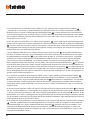
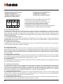
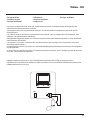
• Installazione del posto interno
• Handset installation
• Installation du poste interne
• Installation der Hausstation
• Instalación de la unidad interior
• Installatie van het intern punt
• Instalação da unidade interna
• Installazione a parete
• Wall mounting installation
• Installation murale
• Wand-Installation
• Instalación mural
• Wandinstallatie
• Instalação de parede
Ø max 5 mm - Ø máx 5 mm
Ø макс 5 mm- Ø maks 5 mm
344692
x 2
- Da acquistare separatamente
- To be purchased separately
- À acheter séparément
- Getrennt zu erwerben
- Comprar por separado
- Apart kopen
- A adquirir separadamente
1
Box
502E - 503E

Video - Kit
19
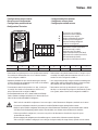
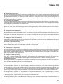
2
4
3

20
N P M
• Il dispositivo deve essere configurato solo fisicamente.
• The device must be only physically configured.
• Le dispositif doit être configuré seule physiquement.
• Das Gerät darf nur physisch konfiguriert werden.
• El dispositivo se ha de configurar solo físicamente.
• Het apparaat hoeft uitsluitend fysiek te worden geconfigureerd.
• O dispositivo deve ser configurado apenas fisicamente.
N - numero del posto interno
I configuratori inseriti nelle sedi N del dispositivo assegnano ad ogni videocitofono un numero di riconosci-
mento all’interno dell’impianto. I posti interni devono essere configurati in modo progressivo. Nel caso di posti
interni collegati in parallelo (in appartamenti senza 346850, max 3), questi dovranno essere configurati con il
medesimo configuratore N. In parallelo al videocitofono di base è possibile installare citofoni, videocitofoni e/o
suonerie supplementari.
P – associazione del posto esterno
I configuratori inseriti nelle sedi P del dispositivo identificano il PE associato, cioè il primo posto esterno da
autoaccendere con la prima pressione del tasto e quale serratura con videocitofono a riposo viene attivata
premendo il tasto serratura.
M – modalità di funzionamento
I configuratori inseriti nelle sedi M del dispositivo assegnano la modalità di funzionamento ai 3 tasti program-
mabili secondo le indicazioni riportate di seguito.
• Configurazione posto
interno
•
Handset
configuration
• Configuration
poste interne
• Konfiguration
Hausstation
• Configuración
unidad interior
• Configuratie
intern punt
•
Configuração
unidade interna
N - internal unit number
The configurators connected to the N sockets of the device assign an identification number within the system to
each video internal unit. The internal units must be configured in progressive order. Internal units with parallel con-
nection (max 3 are allowed inside apartments without item 346850) must be configured using the same N configu-
rator. In parallel with the main video internal unit, additional internal units, video internal units and/or ringtones
may be installed.
P – entrance panel association
The configurators connected to the P sockets of the device identify the associated EP, which is the first entrance panel
that switches itself on when the pushbutton is pressed the first time, as well as which door lock is activated when
pressing the door lock pushbutton while the video internal unit is idle.
M – operating mode
The configurators connected to the M sockets of the device assign the operating modes to the 3 programmable keys
based on the following indications.
N - numéro du poste interne
Les configurateurs placés dans les logements N du dispositif attribuent à chaque vidéophone un numéro de
reconnaissance à l’intérieur de l’installation. Les potes internes doivent être configurés de manière progres-
sive. Dans le cas de postes internes reliées en parallèle (dans des appartements sans 346850, max, 3), ceux-ci
doivent être configurés avec le même configurateur N. En parallèle au vidéophone de base, il est possible
d’installer des interphones, des vidéophones et/ou des sonneries supplémentaires.
P – association du poste interne
Les configurateurs placés dans les logements P du dispositif identifient le PE associé, à savoir le premier poste
externe qui doit s’allumer automatiquement à la première pression sur la touche et la serrure, avec vidéophone
au repos, qui est activée en appuyant sur la touche serrure.
M – modalité de fonctionnement
Les configurateurs placés dans les logements M du dispositif attribuent la modalité de fonctionnement aux 3
touches programmables en fonction des indications figurant ci-après.
La pagina si sta caricando...
La pagina si sta caricando...
La pagina si sta caricando...
La pagina si sta caricando...
La pagina si sta caricando...
La pagina si sta caricando...
La pagina si sta caricando...
La pagina si sta caricando...
La pagina si sta caricando...
La pagina si sta caricando...
La pagina si sta caricando...
La pagina si sta caricando...
La pagina si sta caricando...
La pagina si sta caricando...
La pagina si sta caricando...
La pagina si sta caricando...
La pagina si sta caricando...
La pagina si sta caricando...
La pagina si sta caricando...
La pagina si sta caricando...
La pagina si sta caricando...
La pagina si sta caricando...
La pagina si sta caricando...
La pagina si sta caricando...
La pagina si sta caricando...
La pagina si sta caricando...
La pagina si sta caricando...
La pagina si sta caricando...
-
 1
1
-
 2
2
-
 3
3
-
 4
4
-
 5
5
-
 6
6
-
 7
7
-
 8
8
-
 9
9
-
 10
10
-
 11
11
-
 12
12
-
 13
13
-
 14
14
-
 15
15
-
 16
16
-
 17
17
-
 18
18
-
 19
19
-
 20
20
-
 21
21
-
 22
22
-
 23
23
-
 24
24
-
 25
25
-
 26
26
-
 27
27
-
 28
28
-
 29
29
-
 30
30
-
 31
31
-
 32
32
-
 33
33
-
 34
34
-
 35
35
-
 36
36
-
 37
37
-
 38
38
-
 39
39
-
 40
40
-
 41
41
-
 42
42
-
 43
43
-
 44
44
-
 45
45
-
 46
46
-
 47
47
-
 48
48


Bticino 364622 Istruzioni per l'uso
- Tipo
- Istruzioni per l'uso
in altre lingue
- English: Bticino 364622 Operating instructions
- français: Bticino 364622 Mode d'emploi
- español: Bticino 364622 Instrucciones de operación
- Deutsch: Bticino 364622 Bedienungsanleitung
- Nederlands: Bticino 364622 Handleiding
- português: Bticino 364622 Instruções de operação
Documenti correlati
-
Bticino 364612 Istruzioni per l'uso
-
-
-
-
-
-
-
-
-
