Techly ICA-PLB 161M Manuale utente
- Categoria
- Supporti da parete per schermi piatti
- Tipo
- Manuale utente
La pagina sta caricando ...

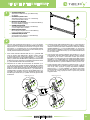
MULTIPLE DESKTOP MONITOR ARM WITH CLAMP
SLIM LCD LED TV TILTING WALL MOUNT
2
www.techly.com
ATTENZIONE: Questa staffa per la
TV deve essere ssata alla parete
in modo sicuro. Se il montaggio
non è stato effettuato in modo
corretto e stabile, ciò potrebbe causare la caduta
della staffa, determinando lesioni o danni a cose
e persone.
CAUTION: This TV mount must
be securely attached to the
vertical wall. If the mount
is not properly installed it
may fall, resulting in possible injury and/or
damage.
ACHTUNG: Diese Fernseher-
Halterung muss sicher an der
Wand befestigt werden. Wird
die Montage nicht auf korrekte
und stabile Weise durchgeführt, könnte dies
zum Herunterfallen der Halterung und dadurch
zu Sach- oder Personenschaden führen.
IT
Gentile Cliente,
grazie per aver scelto un prodotto
Techly.
Istruzioni disimballaggio
• Aprire il cartone con cura, rimuovere il contenuto
e distenderlo su un cartone o altro materiale
protettivo per evitare danni.
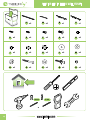
• Vericare che il contenuto della confezione
corrisponda alla lista delle parti nella pagina
successiva per assicurarsi che tutti i componenti
siano presenti e non siano danneggiati. Non
utilizzare parti difettose o danneggiate.
• Leggere attentamente le istruzioni riportate
nel presente manuale prima di procedere
all’installazione.
• Tenere sempre questo manuale per future
consultazioni.
Nota: i componenti e il materiale di ssaggio
forniti in questa confezione non sono indicati
per le installazioni su muri con intelaiatura in
acciaio o su muri con mattoni di cemento. Se
il materiale di ssaggio di cui avete bisogno
non è incluso, consultate la vostra ferramenta
locale per individuare il materiale di montaggio
indicato per la vostra applicazione. Il produttore
non si assume alcuna responsabilità in caso di
ancoraggio non corretto. Assicurarsi dell'integrità
del muro prima di procedere all'installazione.
Rispettare tassativamente il peso massimo
dell'apparecchiatura supportata indicato nella
confezione.
Importanti informazioni
sulla sicurezza
Leggere cortesemente le istruzioni prima
di cominciare l’installazione e seguire
scrupolosamente tutte le indicazioni contenute qui.
Utilizzare adeguati dispositivi di sicurezza durante
l’intallazione.
Contattare del personale qualicato per effettuare
l’installazione:
• Se non avete compreso le indicazioni contenute
in questo manuale o avete dei dubbi in merito alla
sicurezza dell’installazione.
• Se non siete sicuri circa la tipologia del muro
dove effettuare l’installazione del supporto.
Non utilizzate il prodotto per uno scopo o in una
congurazione non espressamente specicata in
queste istruzioni. Si declina qualsiasi responsabilità
per danni derivanti da un errato assemblaggio,
errato montaggio o uso non corretto del prodotto.
Al termine delle operazioni di montaggio assicurarsi
che il tutto sia stato effettuato a regola d'arte.
EN
Dear Customer,
thanks for choosing a Techly product.
Unpacking Instructions
• Carefully open the carton, remove contents and
lay out on cardboard or other protective surface
to avoid damage.
• Check package contents against the Supplied
Parts List in the next page to assure that all
components were received undamaged. Do not
use damaged or defective parts.
• Carefully read all instructions before attempting
installation.
• Please keep this user's manual for future
consultations.
Note: The mounting components and hardware
supplied in this package are not designed for
installations to walls with steel studs or to cinder
block walls. If the hardware you need for your
installation is not included, please consult your
local hardware store for proper mounting hardware
for the application. We are not responsible in
case the mount is not properly installed. Before
proceeding, please make sure the wall is suitable
for installation. Respect the maximum weight
limitation printed on the box.
Important
Safety Information
Please read this instruction before beginning the
installation, and carefully follow all herein contained
recommendations. Use proper safety equipment
during installation.
Please call a qualied installation contractor for
help if you:
• Don't understand these directions or have any
doubts about the safety of the installation.
• Are uncertain about the nature of your wall,
consult a qualied installation contractor.
Do not use this product for any purpose or in
any conguration not explicitly specied in this
instruction. We hereby disclaim any and all
liability for injury or damage arising from incorrect
assembly, incorrect mounting, or incorrect use of
this product.
At the end of the installation make sure the
procedure was correctly observed.
DE
Sehr geehrter Kunde,
danke, dass Sie sich für ein Produkt
von Techly entschieden haben.
Anweisungen zum Auspacken
• Öffnen Sie den Karton vorsichtig, entnehmen Sie
den Inhalt und breiten Sie ihn auf einem Karton
oder anderem schützenden Material aus, um
Schäden zu vermeiden.
• Überprüfen Sie, ob der Inhalt der Verpackung
der Teileliste auf der nächsten Seite entspricht,
um sicherzustellen, dass alle Bauteile vorhanden
und nicht beschädigt sind. Verwenden Sie keine
defekten oder schadhaften Teile.
• Lesen Sie, bevor Sie mit der Installation
beginnen, die Anweisungen in dieser Anleitung
aufmerksam durch.
• Bewahren Sie diese Anleitung zum späteren
Nachschlagen stets auf.
Hinweis: Die in dieser Verpackung enthaltenen
Bauteile und das Befestigungsmaterial sind nicht
für Wandinstallationen mit Stahlrahmen oder
auf Zementsteinwänden geeignet. Sollte das
Befestigungsmaterial, das Sie benötigen, nicht im
Lieferumfang enthalten sein, wenden Sie sich an
Ihren Eisenwarenhändler vor Ort, um das für Ihren
Bedarf erforderliche Montagematerial festzustellen.
Der Hersteller haftet nicht im Fall unkorrekter
Verankerung. Versichern Sie sich vor der
Installation der Unversehrtheit der Wand. Beachten
Sie unbedingt das auf der Verpackung angegebene
Höchstgewicht des Geräts.
Wichtige Informationen
zur Sicherheit
Lesen Sie vor der Installation bitte alle Anweisungen
und befolgen Sie alle hier enthaltenen Angaben
genau. Verwenden Sie bei der Installation geeignete
Sicherheitsvorrichtungen.
Wenden Sie sich in den folgenden Fällen zum
Ausführen der Installation an Fachleute:
• Wenn Sie die in dieser Anleitung enthaltenen
Angaben nicht verstanden haben oder Zweifel
hinsichtlich der Sicherheit der Installation haben.
• Wenn Sie nicht sicher sind, ob die Mauer, an der
der Träger installiert werden soll, geeignet ist.
Verwenden Sie das Produkt nicht für Zwecke
oder in einer Konguration, die in dieser Anleitung
nicht ausdrücklich genannt werden. Jegliche
Haftung aufgrund von Schäden durch fehlerhaften
Zusammenbau, falsche Montage oder unkorrekte
Verwendung des Produkts ist ausgeschlossen.
Nach den Montagevorgängen sicherstellen, dass
alle Schritte fachgerecht ausgeführt wurden.
La pagina sta caricando ...
La pagina sta caricando ...

1
2
MULTIPLE DESKTOP MONITOR ARM WITH CLAMP
SLIM LCD LED TV TILTING WALL MOUNT
5
www.techly.com
M4 D i a mete r B olt
M6 D i a mete r B olt
Dia g ram 2
d
h
l
b
f
j
m
c
M5 D i a mete r B olt
e
i
l
b
M8 D i a mete r B olt
g
k
m
c
n
n
n
n
a 2
a 1
r
A1
R
A2
EN
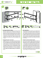
Assemble the Wall plate
Assemble the Wall Plate by 4pcs M5x6 bolt(r)
as diagram.
IT
Assemblare la placca a muro
Assemblare la placca a muro con 4 viti M5x6 (r)
come mostrato dallo schema.
DE
Montieren Sie die Wandtafel
Montieren Sie die Wandplatte mit 4 Schrauben M5x6 (r)
wie in der Abbildung gezeigt,
FR
Assembler la plaque murale
Assembler la plaque murale avec 4 vis M5x6 (R)
comme indiqué dans le schéma
ES
Montar la placa de la pared.
Montar la placa de pared con 4 tornillos M5x6 (r)
como se muestra en el diagrama
PL
Zamontować tablicę na ścianie
Zmontowania płyty ściennej z 4 śrub M5x6 (R),
jak pokazano na schemacie
M4 D iameter B o lt
M6 D ia me te r B olt
Dia g r a m 2
d
h
l
b
f
j
m
c
M5 D iameter B o lt
e
i
l
b
M8 D ia me te r B olt
g
k
m
c
n
n
n
n
a 2
a 1
r
B
N
N
N
C
N
C
M
M
K
G
J
B
L
I
E
F
L
H
D
EN
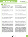
First of all, verify the diameter of the bolt (d, e ,f ,g) your TV requires.
Once you have determined the correct diameter, please see the relative
diagram below. You will thread the bolt into the TV using the correct
lock washer (h, i, j, k) and washer (l,m). You can use the Plastic Space(n)
if the bolt is too long. Please make sure the monitor brackets (b, c) are
vertically centered and level with each other.
IT
Prima di tutto, vericate il diametro delle viti (d, e, f, g) richieste dalla
vostra TV. Appena avete determinato il diametro corretto, visionate
lo schema sotto riportato. Dovete quindi inlare le viti nel retro della
televisione utilizzando le corrette rondelle dentellate (h, i, j, k) e rondelle
piane (l, m). Potete usare dei distanziatori in plastica (n) se la vite dovesse
risultare troppo lunga. Assicuratevi che le staffe di supporto del monitor
(b, c) siano centrate verticalmente e allo stesso livello.
DE
Überprüfen Sie als erstes den Durchmesser der Schrauben (d, e,
f, g), die Sie für Ihren Fernseher benötigen. Sobald Sie den korrekten
Durchmesser festgestellt haben, nehmen Sie die Abbildung unten zur
Hand. Dann müssen Sie die Schraube in die Rückseite des Fernsehers
einsetzen und dazu die korrekten gezahnten (h, i, j, k) und achen (l, m)
Unterlegscheiben verwenden. Sie können die Kunststoff-Space (n) zu
verwenden, wenn der Bolzen zu lang ist. Vergewissern Sie sich, dass
die Halterungen des Monitors (b, c) vertikal und auf der gleichen Höhe
zentriert sind.
FR
Avant toute chose, vérier le diamètre des vis (d, e, f, g) en fonction de la
TV. Une fois le diamètre correct trouvé, consulter le schéma ci-dessous.
Insérer les vis dans la partie arrière du téléviseur en utilisant les rondelles
dentelées adaptées (h, i, j, k) et les rondelles plates (l, m). Vous pouvez
utiliser l'espace en plastique (n) si le boulon est trop long. S'assurer que
les crochets de supports de l'écran (b, c) sont centrés verticalement et
sont au même niveau.
ES
Como primera cosa, controlar el diámetro de los tornillos (d, e, f, g) que
la tele necesita. Tras haber determinado el diámetro correcto, visualicen
el esquema que se muestra a continuación: Tendrán que introducir
los tornillos en la parte trasera de la tele utilizando arandelas correctas
dentadas (h, i, j, k) y arandelas llanas (l, m). Usted puede utilizar el espacio
plástico (n) si el perno es demasiado largo. Asegúrense de que los estribos
de soporte del monitor (b, c) estén centradas en vertical y al mismo nivel.
PL
Przede wszystkim należy sprawdzić czy średnica śrub (d, e, f, g) jest
właściwa dla telewizora. Po ustaleniu średnicy śrub spójrz na diagram
obok. Śruby należy przykręcić używając odpowiednich podkładek
ząbkowanych (h, i, j, k) oraz podkładek (l, m). Możesz wykorzystać
przestrzeń Plastic (n), jeśli śruba jest zbyt długi. Należy zwrócić uwagę
aby uchwyty (b, c) były przykręcone równo w pionie oraz poziomie
względem siebie.

MULTIPLE DESKTOP MONITOR ARM WITH CLAMP
SLIM LCD LED TV TILTING WALL MOUNT
6
www.techly.com
3
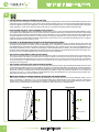
EN
Wood stud mounting:
The wall plate (a) must be mounted to two wood studs at least
16"(406mm) apart. Use a stud nder to locate two adjacent studs.
It is a good idea to verify where the studs are located with an awl
or thin nail shown in the diagram. Pre-drill a 2.4" (60mm) deep
hole at the desired height in each stud using a 5/32" (4mm) drill
bit. Make sure these holes are in the center area of the studs and
level with each other. Use the wall plate as a template to mark the
location of the second hole in each stud. Drill 2.4" (60mm) deep
holes using the 5/32" (4mm) drill bit in the marked locations.Attach
the wall plate to the wall using the 4pcs lag bolts (o) and 4pcs lag
bolt washers (p).
IT
Installazione su pareti con intelaiatura in legno
La placca a muro (a) deve essere montata su assi di legno ad
almeno 406mm di distanza. Utilizzate l’apposito strumento per
individuare due assi vicine. Potrebbe essere una buona idea per
vericare dove le assi sono posizionate utilizzare un punteruolo o
un chiodo sottile come mostrato nello schema. Praticate un foro
2.4” di profondità (circa 60mm) all’altezza desiderata in ciascuna
asse utilizzando una punta da 5/32” (4mm). Assicuratevi che i
fori siano posizionati nella parte centrale delle assi e che siano
allo stesso livello. Utilizzate la placca a muro come sagoma per
segnare la posizione del secondo foro su ciascuna asse. Praticate
gli altri fori con profondità 60mm (2.4”) con una punta da 5/32”
(4mm) nelle posizioni segnate. Fissate la placca a muro. usando le
4 viti per i tasselli (o) e le 4 rondelle per i tasseli (p).
EN
Mounting the Wall Plate to the Wall
Brick, Solid Concrete and Concrete Block mounting: Use the wall
plate(a) as a template to mark 4 hole locations on the wall. Two in
the top row of slots and two more in the bottom row. Make sure
these holes are leveled and there is at least 6" (150mm) distance
between any two holes. Pre-drill these holes with a 3/8" (10mm)
masonry bit to at least 2.4" (60mm) in depth. Insert a concrete an-
chor (q) into each of these holes. Make sure. the anchor is seated
completely ush with the concrete surface even if there is a layer
of drywall or other material in front. Attach the wall plate to the
wall using 4pcs lag bolts(o) and 4pcs lag bolt washers(p), shown
in diagram.
IT
Montaggio della placca a muro sul muro
Installazione su mattone, cemento armato o blocchi di calcestruzzo.
Utiliizare la placca a muro come sagoma per segnare la posizione
dei 4 fori da effettuare sul muro. Due fori sono situati nella parte
superiore e altri due nella parte inferiore della staffa. Assicuratevi che
i fori siano a livello e che ci siano almeno 150mm (6”) di distanza tra
due fori. Praticare i fori con una punta da trapano da 3/8” (10mm) in
modo tale che abbiano almeno 2.4” di profondità (60mm). Inserire
un tassello (q) in ciascuno di questi fori. Assicurarsi che ciascun
tassello sia inserito completamente e sia a lo con la supercie in
calcestruzzo, anche se, frontalmente, vi è uno strato in cartongesso
o di altro materiale. Fissare la placca a muro al muro utilizzando le 4
viti per i tasselli (o), le 4 rondelle dei tasselli (p) come mostrato nello
schema.
Dia g r a m 4 A Dia g r a m 4 B
a
b, c
b, c
a
s a fety b ol t
wa l l
wa l l
16 i n c h
16 i n c h
16 i n c h
Dia g r a m 3 BDia g r a m 3 A
S tu d F i nd er
o
p
q
P
Q
O
2
1
1
2
1
2
2
1
60 mm
ø 10 mm
2
1
2
1
2
2
1
31
60 mm
ø 4 mm
Dia g ra m 4 A Dia g ra m 4 B
a
b, c
b, c
a
s a fe ty b o lt
wa l l
wa l l
16 i n c h
16 i n c h
16 i n c h
Dia g ra m 3 BDia g ra m 3 A
S tu d F in der
o
p
P
O
La pagina sta caricando ...
La pagina sta caricando ...
-
 1
1
-
 2
2
-
 3
3
-
 4
4
-
 5
5
-
 6
6
-
 7
7
-
 8
8


Techly ICA-PLB 161M Manuale utente
- Categoria
- Supporti da parete per schermi piatti
- Tipo
- Manuale utente
in altre lingue
- English: Techly ICA-PLB 161M User manual
- français: Techly ICA-PLB 161M Manuel utilisateur
- español: Techly ICA-PLB 161M Manual de usuario
- Deutsch: Techly ICA-PLB 161M Benutzerhandbuch
- polski: Techly ICA-PLB 161M Instrukcja obsługi