Genius Euro Breeze 06 Istruzioni per l'uso
- Tipo
- Istruzioni per l'uso

EURO BREEZE 06
EURO BREEZE 06

AVVERTENZE PER LíINSTALLATORE
OBBLIGHI GENERALI PER LA SICUREZZA
1) ATTENZIONE! È importante per la sicurezza delle persone seguire attenta-
mente tutta l’istruzione. Una errata installazione o un errato uso del prodotto
può portare a gravi danni alle persone.
2) Leggere attentamente le istruzioni prima di iniziare l’installazione del prodot-
to.
3) I materiali dell’imballaggio (plastica, polistirolo, ecc.) non devono essere
lasciati alla portata dei bambini in quanto potenziali fonti di pericolo.
4) Conservare le istruzioni per riferimenti futuri.
5) Questo prodotto è stato progettato e costruito esclusivamente per l’utilizzo
indicato in questa documentazione. Qualsiasi altro utilizzo non espressamente
indicato potrebbe pregiudicare l’integrità del prodotto e/o rappresentare
fonte di pericolo.
6) GENIUS declina qualsiasi responsabilità derivata dall’uso improprio o diverso
da quello per cui l’automatismo è destinato.
7) Non installare l’apparecchio in atmosfera esplosiva: la presenza di gas o fumi
infiammabili costituisce un grave pericolo per la sicurezza.
8) Gli elementi costruttivi meccanici devono essere in accordo con quanto
stabilito dalle Norme EN 12604 e EN 12605.
Per i Paesi extra-CEE, oltre ai riferimenti normativi nazionali, per ottenere un
livello di sicurezza adeguato, devono essere seguite le Norme sopra riporta-
te.
9) GENIUS non è responsabile dell’inosservanza della Buona Tecnica nella co-
struzione delle chiusure da motorizzare, nonché delle deformazioni che do-
vessero intervenire nell’utilizzo.
10) L’installazione deve essere effettuata nell’osservanza delle Norme EN 12453
e EN 12445. Il livello di sicurezza dell’automazione deve essere C+D.
11) Prima di effettuare qualsiasi intervento sull’impianto, togliere l’alimentazione
elettrica e scollegare le batterie.
12) Prevedere sulla rete di alimentazione dell’automazione un interruttore onni-
polare con distanza d’apertura dei contatti uguale o superiore a 3 mm. È
consigliabile l’uso di un magnetotermico da 6A con interruzione onnipolare.
13) Verificare che a monte dell’impianto vi sia un interruttore differenziale con
soglia da 0,03 A.
14) Verificare che l’impianto di terra sia realizzato a regola d’arte e collegarvi le
parti metalliche della chiusura.
15) L’automazione dispone di una sicurezza intrinseca antischiacciamento costi-
tuita da un controllo di coppia. E' comunque necessario verificarne la sogli di
intervento secondo quanto previsto dalle Norme indicate al punto 10.
16) I dispositivi di sicurezza (norma EN 12978) permettono di proteggere eventuali
aree di pericolo da Rischi meccanici di movimento, come ad Es. schiaccia-
mento, convogliamento, cesoiamento.
17) Per ogni impianto è consigliato l’utilizzo di almeno una segnalazione luminosa
nonché di un cartello di segnalazione fissato adeguatamente sulla struttura
dell’infisso, oltre ai dispositivi citati al punto “16”.
18) GENIUS declina ogni responsabilità ai fini della sicurezza e del buon funziona-
mento dell’automazione, in caso vengano utilizzati componenti dell’impian-
to non di produzione GENIUS.
19) Per la manutenzione utilizzare esclusivamente parti originali GENIUS.
20) Non eseguire alcuna modifica sui componenti facenti parte del sistema
d’automazione.
21) L’installatore deve fornire tutte le informazioni relative al funzionamento
manuale del sistema in caso di emergenza e consegnare all’Utente utilizzato-
re dell’impianto il libretto d’avvertenze allegato al prodotto.
22) Non permettere ai bambini o persone di sostare nelle vicinanze del prodotto
durante il funzionamento.
23) Tenere fuori dalla portata dei bambini radiocomandi o qualsiasi altro datore
di impulso, per evitare che l’automazione possa essere azionata involontaria-
mente.
24) Il transito tra le ante deve avvenire solo a cancello completamente aperto.
25) L’utente utilizzatore deve astenersi da qualsiasi tentativo di riparazione o
d’intervento e deve rivolgersi solo ed esclusivamente a personale qualificato
GENIUS o centri d’assistenza GENIUS.
26) Tutto quello che non è previsto espressamente in queste istruzioni non è
permesso
IMPORTANT NOTICE FOR THE INSTALLER
GENERAL SAFETY REGULATIONS
1) ATTENTION! To ensure the safety of people, it is important that you read all
the following instructions. Incorrect installation or incorrect use of the
product could cause serious harm to people.
2) Carefully read the instructions before beginning to install the product.
3) Do not leave packing materials (plastic, polystyrene, etc.) within reach of
children as such materials are potential sources of danger.
4) Store these instructions for future reference.
5) This product was designed and built strictly for the use indicated in this
documentation. Any other use, not expressly indicated here, could compro-
mise the good condition/operation of the product and/or be a source of
danger.
6) GENIUS declines all liability caused by improper use or use other than that for
which the automated system was intended.
7) Do not install the equipment in an explosive atmosphere: the presence of
inflammable gas or fumes is a serious danger to safety.
CONSIGNES POUR L'INSTALLATEUR
R»GLES DE S…CURIT…
1) ATTENTION! Il est important, pour la sécurité des personnes, de suivre à la
lettre toutes les instructions. Une installation erronée ou un usage erroné
du produit peut entraîner de graves conséquences pour les personnes.
2) Lire attentivement les instructions avant d'installer le produit.
3) Les matériaux d'emballage (matière plastique, polystyrène, etc.) ne doivent
pas être laissés à la portée des enfants car ils constituent des sources
potentielles de danger.
4) Conserver les instructions pour les références futures.
5) Ce produit a été conçu et construit exclusivement pour l'usage indiqué dans
cette documentation. Toute autre utilisation non expressément indiquée
pourrait compromettre l'intégrité du produit et/ou représenter une source
de danger.
6) GENIUS décline toute responsabilité qui dériverait d'usage impropre ou
différent de celui auquel l'automatisme est destiné.
7) Ne pas installer l'appareil dans une atmosphère explosive: la présence de
gaz ou de fumées inflammables constitue un grave danger pour la sécurité.
8) Les composants mécaniques doivent répondre aux prescriptions des Normes
EN 12604 et EN 12605.
Pour les Pays extra-CEE, l'obtention d'un niveau de sécurité approprié exige
non seulement le respect des normes nationales, mais également le respect
des Normes susmentionnées.
9) GENIUS n'est pas responsable du non-respect de la Bonne Technique dans la
construction des fermetures à motoriser, ni des déformations qui pourraient
intervenir lors de l'utilisation.
10) L'installation doit être effectuée conformément aux Normes EN 12453 et EN
12445. Le niveau de sécurité de l'automatisme doit être C+D.
11) Couper l'alimentation électrique et déconnecter la batterie avant toute
intervention sur l'installation.
12) Prévoir, sur le secteur d'alimentation de l'automatisme, un interrupteur
omnipolaire avec une distance d'ouverture des contacts égale ou supérieure
à 3 mm. On recommande d'utiliser un magnétothermique de 6A avec
interruption omnipolaire.
13) Vérifier qu'il y ait, en amont de l'installation, un interrupteur différentiel avec
un seuil de 0,03 A.
14) Vérifier que la mise à terre est réalisée selon les règles de l'art et y connecter
les pièces métalliques de la fermeture.
15) L'automatisme dispose d'une sécurité intrinsèque anti-écrasement, formée
d'un contrôle du couple. Il est toutefois nécessaire d'en vérifier le seuil
d'intervention suivant les prescriptions des Normes indiquées au point 10.
16) Les dispositifs de sécurité (norme EN 12978) permettent de protéger des
zones éventuellement dangereuses contre les Risques mécaniques du
mouvement, comme l'écrasement, l'acheminement, le cisaillement.
8) The mechanical parts must conform to the provisions of Standards EN 12604
and EN 12605.
For non-EU countries, to obtain an adequate level of safety, the Standards
mentioned above must be observed, in addition to national legal regulations.
9) GENIUS is not responsible for failure to observe Good Technique in the
construction of the closing elements to be motorised, or for any deformation
that may occur during use.
10) The installation must conform to Standards EN 12453 and EN 12445. The safety
level of the automated system must be C+D.
11) Before attempting any job on the system, cut out electrical power and
disconnect the batteries.
12) The mains power supply of the automated system must be fitted with an all-
pole switch with contact opening distance of 3mm or greater. Use of a 6A
thermal breaker with all-pole circuit break is recommended.
13) Make sure that a differential switch with threshold of 0.03 A is fitted upstream
of the system.
14) Make sure that the earthing system is perfectly constructed, and connect
metal parts of the means of the closure to it.
15) The automated system is supplied with an intrinsic anti-crushing safety device
consisting of a torque control. Nevertheless, its tripping threshold must be
checked as specified in the Standards indicated at point 10.
16) The safety devices (EN 12978 standard) protect any danger areas against
mechanical movement Risks, such as crushing, dragging, and shearing.
17) Use of at least one indicator-light is recommended for every system, as well
as a warning sign adequately secured to the frame structure, in addition to
the devices mentioned at point “16”.
18) GENIUS declines all liability as concerns safety and efficient operation of the
automated system, if system components not produced by GENIUS are used.
19) For maintenance, strictly use original parts by GENIUS.
20) Do not in any way modify the components of the automated system.
21) The installer shall supply all information concerning manual operation of the
system in case of an emergency, and shall hand over to the user the warnings
handbook supplied with the product.
22) Do not allow children or adults to stay near the product while it is operating.
23) Keep remote controls or other pulse generators away from children, to
prevent the automated system from being activated involuntarily.
24) Transit through the leaves is allowed only when the gate is fully open.
25) The end user has to be refrained to any tempted of repairing end he mast
contact only qualified Genius’ s personnel, or Genius’s technical after sale
offices.
26) Anything not expressly specified in these instructions is not permitted.

1
ITALIANO
INDICE
1. DESCRIZIONE E CARATTERISTICHE TECNICHE pag.2
3. PREDISPOSIZIONI ELETTRICHE (impianto standard) pag.2
2. DIMENSI0NI pag.2
4. INSTALLAZI0NE DELL'AUTOMAZIONE pag.3
4.1. VERIFICHE PRELIMINARI pag.3
4.2. POSIZIONAMENTO BRACCI TELESCOPICI pag.3
4.3. POSIZIONAMENTO OPERATORE/LONGHERONE pag.3
4.4. SEQUENZA DI MONTAGGIO pag.3
4.5. REGOLAZIONE DEI CONTRAPPESI pag.4
5. MONTAGGIO GRUPPO MOTORIDUTTORE pag.4
6. MESSA IN FUNZIONE pag.4
6.1. COLLEGAMENTO SCHEDA ELETTRONICA pag.4
7. PROVA DELL'AUTOMAZIONE pag.5
8. FUNZIONAMENTO MANUALE pag.5
9. RIPRISTINO DEL FUNZIONAMENTO NORMALE pag.5
10. MANUTENZIONE pag.5
11. RIPARAZIONI pag.5
DICHIARAZIONE CE DI CONFORMITÀ PER MACCHINE
(DIRETTIVA 98/37/CE)
Fabbricante: GENIUS S.p.A.
Indirizzo: Via Padre Elzi, 32 - 24050 - Grassobbio BERGAMO - ITALIA
Dichiara che: L'operatore mod. EURO BREEZE 06 - EURO BREEZE 06 C - EURO BREEZE 06 24V
• è costruito per essere incorporato in una macchina o per essere assemblato con altri macchinari per costituire una macchina ai
sensi della Direttiva 98/37/CE;
• è conforme ai requisiti essenziali di sicurezza delle seguenti altre direttive CEE:
73/23/CEE e successiva modifica 93/68/CEE.
89/336/CEE e successiva modifica 92/31/CEE e 93/68/CEE
inoltre dichiara che non è consentito mettere in servizio il macchinario fino a che la macchina in cui sarà incorporato o di cui
diverrà componente sia stata identificata e ne sia stata dichiarata la conformità alle condizioni della Direttiva 98/37/CE.
Grassobbio, 01-06-2006
L’amministratore delegato
D.Gianantoni
Note per la lettura dell'istruzione
Leggere completamente questo manuale di installazione prima di iniziare l'installazione del prodotto.
Il simbolo evidenzia note importanti per la sicurezza delle persone e l'integrità dell'automazione.
Il simbolo richiama l'attenzione su note riguardanti le caratteristiche od il funzionamento del prodotto.

2
ITALIANO
2x1.5
3x0.5
2x1.5 + GROUND
2x0.5
2x0.5
4x0.5
2x1.5
3x0.5
2x0.5
2x0.5
4x0.5
5x1.5 + GROUND
2x1.5 + GROUND
3
1
4
5
5
6
1
2
3
4
5
5
6
1
2
3
4
5
6
7
8
9
10
100
175
50
115
685
1300 - 1500 - 2000
AUTOMAZIONE EURO BREEZE 06
L’automazione EURO BREEZE 06 consente di automatizzare porte
basculanti a contrappesi di garages residenziali.
E' costituita da un operatore elettromeccanico, un'apparec-
chiatura elettronica di comando con lampada di cortesia e un
carter di protezione integrati in un unico monoblocco da ap-
plicare al telo della basculante con gli opportuni accessori.
Il sistema irreversibile garantisce il blocco meccanico della por-
ta quando il motore non è in funzione e quindi non occorre
installare alcuna serratura; uno sblocco manuale rende
manovrabile la porta in caso di black-out o disservizio.
La sicurezza antischiacciamento è garantita da un dispositivo
elettronico regolabile.
L'automazione EURO BREEZE 06 consente anche l'applicazione
di due operatori (EURO BREEZE 06 C + EURO BREEZE 06) sulla
stessa porta.
L'automazione EURO BREEZE 06 è stata progettata e costruita per
controllare l’accesso veicolare. Evitare qualsiasi altro diverso
utilizzo.
1retraC
2)lanoitpo(etnasluP
3acinorttelearutaihccerappA
4arutaihccerappaerotinetnoC
5enorehgnoL
6enoizatoridoreb
lA
7occolbS
8erottudirotomoppurG
9occolbsidevaihC
01)lanoitpo(redocnE
TAB. 1 CARATTERISTICHE TECNICHE MOTORIDUTTORI
OLLEDOM
60EZEERBORUE
otnelV032 V032 V42
enoizatnemilA zH05~V032cdV42
atibrossaaznetoP W082W053W07
atibrossaetnerroC A2.1A5.1A3
xamaippoC mN052mN003mN052
otnupsiderotasnednoC V004Fµ8V004Fµ01/
enoizetorpomreT C°041/
erotomledirigidoremuN nim/g009nim/g0041
enoizudiri
dotroppaR 007:1
eralognaàticoleV ces/°8ces/°21
3SozzilituidazneuqerF %03%001
aro/ilciC
)asrocenifaznes(02
)asro
cenifnoc(03
05
etneibmaarutarepmeT C°55+/C°02-
azzehgraL
)m(atropxam
erotarepo13.33
irotarepo254
)m(atropxamazzet
lA 3
atropxamoseP m/gK01
2
erotarepooseP gK5.7
enoizetorpidodarG
13PI
)arutaihccerappaaznes(44PI
erotarepoinoisnemiD 2.giFideV
2. DIMENSI0NI
3. PREDISPOSIZIONI ELETTRICHE (impianto standard)
* Quote in mm
1C60EZEERBORUEerotarepO4evaihcaetnasluP
260EZEERBORUEerotarepO5elullecotoF
3erotaiggepmaL6azzerucisidatsoC
²mmnie
sserpseonosivaciedinoizeseL•
1. DESCRIZIONE E CARATTERISTICHE TECNICHE
FIG.1
F
IG.2
F
IG.3

3
ITALIANO
A
B
C
S1
S2
=
=
=
=
~10cm
~10cm
~10cm
A
B
=
=
4. INSTALLAZI0NE DELL'AUTOMAZIONE
4.1. VERIFICHE PRELIMINARI
Per la sicurezza e per un corretto funzionamento dell’automa-
zione, verificare l’esistenza dei seguenti requisiti:
• La struttura della porta deve essere idonea per essere
automatizzata. In particolare verificare che le dimensioni della
porta siano conformi a quelle indicate nelle caratteristiche
tecniche e sia sufficientemente robusta.
• Controllare l'efficienza dei cuscinetti e dei giunti della porta.
• Verificare che la porta sia priva di attriti; eventualmente
pulire ed oliare le guide con lubrificante al silicone, evitando
di utilizzare grasso.
• Verificare che la porta sia correttamente bilanciata.
• Rimuovere le chiusure meccaniche della porta, affinchè sia
l'automatismo a bloccarla in chiusura.
• Verificare l’esistenza di una efficiente presa di terra per il
collegamento del motoriduttore.
L'operatore EURO BREEZE 06 automatizza porte basculanti a
contrappesi di diverse tipologie. In fig. 4 sono rappresentate le
più diffuse:
a) a telo unico debordante
b) a telo snodato debordante
c) a telo unico non debordante con guide orizzontali
4.4. SEQUENZA DI MONTAGGIO
L'installazione inizia a basculante chiusa e operatore sbloccato
(vedi capitolo 8).
1) Definire il posizionamento dell'albero dell'operatore come
segue:
• basculante a telo unico debordante (fig. 8)
L'asse di rotazione dell'al-
bero dell'operatore deve
essere, a basculante chiu-
sa, circa 10 cm più in bas-
so rispetto all'asse di rota-
zione della porta. Il punto
di attacco dei bracci te-
lescopici deve essere il più
vicino possibile al punto
di fissaggio del braccio
della porta.
• basculante a telo snodato (fig. 9)
L'asse di rotazione dell'al-
bero dell'operatore deve
essere, a basculante chiu-
sa, circa 10 cm più in bas-
so rispetto all'asse di rota-
zione delle cerniere di ar-
ticolazione della porta (rif.
A).
Il punto di attacco dei
bracci telescopici deve
essere il più vicino possibile
al punto di fissaggio delle
cerniere della porta (rif. B).
• basculante con guide orizzontali (fig. 10)
L'asse di rotazione dell'al-
bero dell'operatore deve
coincidere con la linea di
mezzeria tra i due cusci-
netti.
Il punto di attacco dei
bracci telescopici deve
essere il più vicino possibi-
le al punto di congiunzio-
ne delle guide superiore e
verticale.
2) Fissare verticalmente il longherone sui rinforzi del telo
basculante con viti adeguate alla struttura della porta; è
consigliabile l'utilizzo di inserti filettati.
• Posizionare il longherone in modo che l'estremità dove
c'è il riferimento "E", sia rivolta verso l'alto. Questo riferi-
mento indica dove andrà ad essere posizionata l'ap-
parecchiatura.
• Il longherone ha una serie di fori Ø 8mm che consento-
no, una volta fissato, di installare l'operatore a varie
altezze.
• Verificare che la posizione di fissaggio del longherone
consenta il montaggio dell'operatore rispettando la
posizione dell'albero precedentemente determina-
ta.
• Nel caso di installazione di due operatori sulla stessa
porta, entrambi gli alberi devono essere allineati alla
stessa altezza.
3) Fissare l'operatore al longherone utilizzando la viteria in do-
tazione come da fig. 11.
4) Saldare le staffe superiori di aggancio dei bracci telescopici
rispettando, per il posizionamento, le indicazioni relative al
tipo di basculante.
Nel caso dei bracci curvi con installazione sovrapposta, è
possibile saldare le staffe direttamente sui bracci esistenti
della porta.
Fissare le guaine dei bracci telescopici alle staffe utilizzando
i perni e la viteria in dotazione come da fig. 11.
5) Innestare completamente i tubi di trasmissione sull'albero e
tagliarli a misura come in figg. 6 e 7.
Se si utilizzano i finecorsa (opzionali), inserire prima le
camme, come in fig. 11.
4.2. POSIZIONAMENTO BRACCI TELESCOPICI
Lo spazio tra braccio di
bilanciamento esistente e infisso
(quota "S1" di fig. 5) deve essere
almeno 15 mm. per consentire la
rotazione dei bracci telescopici
affiancati.
In caso contrario è possibile utiliz-
zare i bracci telescopici curvi che
permettono l'installazione
sovrapposta ai bracci di
bilanciamento esistenti, verifican-
do che lo spazio fra telo della
basculante e infisso sia almeno
20 mm. (quota "S2" di fig. 5).
4.3. POSIZIONAMENTO OPERATORE/LONGHERONE
Rispettando le misure riportate in Tab.1, utilizzare un solo opera-
tore al centro della porta come in fig. 6 oppure due operatori ai
lati della porta come in fig. 7.
L'operatore è predisposto per installare il gruppo motoriduttore
in modo da avere l'albero di rotazione a due diverse altezze
(vedi capitolo 5).
Le istruzioni seguenti sono valide per entrambe le possibilità di
montaggio anche se fanno riferimento all'installazione dell'ope-
ratore con l'uscita dell'albero di rotazione del motoriduttore al
centro dell'applicazione.
FIG.4
F
IG.5
F
IG.6 FIG.7
F
IG.8
F
IG.9
F
IG.10

4
ITALIANO
FCC
FCA
2
2
9
3
4
4
3
2
2
5
5
6
6
7
7
8
8
9
10
10
11
1
~ 1cm
~
1cm
~ 1cm
~
1cm
A
B
~ 1cm
~1cm
A
B
6) Inserire le staffe nei tubi di trasmissione e fissarle con viti sul telo
della porta mantenendo un corretto allineamento.
7) Serrare i grani posti sulle boccole dei tubi di trasmissione.
8) Portare la basculante in apertura e adattare la lunghezza
dei bracci telescopici come segue:
• bracci dritti (fig. 12)
Tagliare la guaina in prossimità del tubo di trasmissione (rif.
A). Introdurre il braccio nella guaina e tagliare in prossi-
mità del perno di rotazione (rif. B).
1enorehgnoL
2icipocseleticcarbiedoicnaggaidaffatS
3enoissimsartidobuT
4)lanoitpo(asrocenifammaC
5enoissimsarti
dobutledaffatS
6oiggarresidonarG
7ottirdoiccarbledaniauG
8ottirdoiccarB
9ovrucoiccarbledaniauG
01ovrucoiccarB
11o
ccolbsidevaihC
• bracci curvi (fig. 13)
Simulare il posizionamento del braccio telescopico come
indicato in figura 13. Tagliare la guaina nel punto A e il
braccio nel punto B.
Lasciare un gioco di circa 1 cm in prossimità dei punti di
battuta.
9) Accoppiare il braccio al tubo di trasmissione ed eseguire
robuste saldature.
4.5. REGOLAZIONE DEI CONTRAPPESI
Al termine dell'installazione meccanica verificare il bilanciamento
della basculante, che potrebbe risultare variato dal peso del-
l'operatore e degli accessori; se necessario, adeguare i con-
trappesi.
Un bilanciamento ottimale si ha quando la porta, in posizione
intermedia (45°) e con l'operatore sbloccato, rimane in equili-
brio.
Verificare inoltre, muovendo la porta manualmente, che il mo-
vimento di apertura e chiusura sia lineare e non presenti sussulti
o irregolarità.
5. MONTAGGIO GRUPPO MOTORIDUTTORE
In base alle esigenze, è possibile montare il gruppo motoridutto-
re in due modi:
• Con l'albero di rotazione in alto (fig. 14)
Il supporto scheda viene fissato al motoriduttore mediante 4
viti che stringono dadi inseriti nelle apposite guide.
Il fissaggio del motoriduttore in questo modo permette il suc-
cessivo montaggio dell'encoder (optional).
• Con l'albero di rotazione in basso (fig. 15)
Il supporto scheda viene fissato alla calotta del motore elet-
trico mediante 4 viti.
Il fissaggio del motoriduttore in questo modo non permette il
successivo montaggio dell'encoder (optional).
Il carter è predisposto per entrambe le applicazioni (da notare
che lo sblocco viene a trovarsi in posizioni differenti).
6. MESSA IN FUNZIONE
6.1. COLLEGAMENTO SCHEDA ELETTRONICA
Prima di effettuare qualsiasi tipo di intervento sull'appa-
recchiatura elettronica (collegamenti, programma-
zione, manutenzione) togliere sempre l’alimentazio-
ne elettrica.
Seguire i punti 10, 11, 12, 13, 14 degli OBBLIGHI GENERALI PER LA
SICUREZZA.
Seguendo le indicazioni di fig.3 predisporre le canalizzazioni ed
effettuare i collegamenti elettrici dell’apparecchiatura elettro-
nica con gli accessori prescelti.
Separare sempre i cavi di alimentazione da quelli di comando
e di sicurezza (pulsante, ricevente, fotocellule ecc.). Per evitare
qualsiasi disturbo elettrico utilizzare guaine separate.
Seguire poi le istruzioni dell'apparecchiatura elettronica pro-
grammandola secondo le proprie esigenze.
FIG.11
F
IG.12
F
IG.13

5
ITALIANO
B
A
OK ENCODER NO ENCODER
6.2. VERIFICA DEL SENSO DI ROTAZIONE
1) Togliere alimentazione all'impianto.
2) Portare manualmente la porta a metà apertura.
3) Bloccare l'operatore (vedi capitolo 9)
4) Ripristinare la tensione di alimentazione.
5) Inviare un impulso di apertura (START) e verificare che si co-
mandi un'apertura della porta.
Nel caso si comandi una chiusura, è necessario invertire sulla
morsettiera della scheda le fasi del motore elettrico (cavi marro-
ne e nero).
Nell'applicazione con due operatori, ai morsetti "COM,OP,CL",
della scheda di comando e della scheda porta luce di corte-
sia, assegnare la stessa colorazione dei cavi e, dovendo inverti-
re le fasi, invertirle per entrambi i motori.
6.3. REGOLAZIONE DEI FINECORSA (OPZIONALI)
Aprire la porta fino al punto desiderato; regolare la camma fino
all' attivazione del micropulsante FCA (fig. 11).
Chiudere la porta; regolare la camma fino all' attivazione del
micropulsante FCC (fig. 11).
Se si utilizza una centrale di comando con rallentamen-
ti, anticipare l'attivazione dei micropulsanti.
Serrare le viti poste sulle camme.
6.4. MONTAGGIO CARTER
Fissare il carter serrando le quattro viti laterali.
Applicare al carter i due tappi di plastica da montare a pres-
sione nelle asole laterali non utilizzate dall'albero dell'operatore.
Applicare al carter il tappo di plastica da montare a pressione
nell'asola frontale non utilizzata per accedere al sistema di sbloc-
co.
7. PROVA DELL'AUTOMAZIONE
Procedere alla verifica funzionale accurata dell'automazione
e di tutti gli accessori ad essa collegati.
Consegnare al Cliente la pagina "Guida per l'Utente" e illustrare
il corretto funzionamento e utilizzo dell'automazione.
8. FUNZIONAMENTO MANUALE
L'operatore è dotato di uno sblocco d'emergenza azionabile
dall'interno; è possibile, a richiesta, applicare una serratura sul
telo che permette l'azionamento dello sblocco dall'esterno.
Nel caso sia necessario azionare manualmente la porta a cau-
sa di mancanza di alimentazione elettrica o disservizio dell'au-
tomazione, è necessario agire sul dispositivo di sblocco come
segue:
- Dall'interno (fig. 17)
Inserire la chiave a brugola in dotazione e ruotare in senso
orario di circa mezzo giro fino all'arresto.
In base al tipo d'installazione, lo sblocco può trovarsi sul
lato destro (A) o sinistro (B).
- Dall'esterno (fig. 18)
1) Aprire lo sportellino di protezione ed inserire la chiave.
2) Ruotare in senso antiorario fino all'arresto ed estrarre il corpo
serratura.
3) Inserire la chiave a brugola in dotazione e ruotare in senso
antiorario di circa mezzo giro fino all'arresto.
9. RIPRISTINO DEL FUNZIONAMENTO NORMALE
Per evitare che un impulso involontario possa azionare la porta
durante la manovra, prima di ribloccare l'operatore togliere
alimentazione all'impianto.
• Dall'interno (fig. 17)
Inserire la chiave a brugola in dotazione e ruotare in senso
antiorario di circa mezzo giro fino all'arresto.
In base al tipo d'installazione, lo sblocco può trovarsi sul
lato destro (A) o sinistro (B).
• Dall'esterno (fig. 18)
1) Inserire la chiave a brugola in dotazione e ruotare in senso
orario di circa mezzo giro fino all'arresto.
2) Estrarre la chiave a brugola ed inserire il corpo serratura.
3) Ruotare la chiave in senso orario fino a quando è possibile
estrarla; richiudere lo sportellino di protezione.
10. MANUTENZIONE
Effettuare almeno semestralmente le seguenti operazioni:
• Verifica della corretta regolazione di coppia del motore.
• Controllo dei rulli e guide di scorrimento della porta; eventua-
le pulizia e lubrificazione.
• Controllo efficienza del sistema di sblocco.
• Controllo efficienza dei dispositivi di sicurezza.
11. RIPARAZIONI
L’utente utilizzatore deve astenersi da qualsiasi tentativo di ri-
parazione o d’intervento e deve rivolgersi solo ed esclusivamen-
te a personale qualificato GENIUS o centri d’assistenza GENIUS.
FIG.15FIG.14
FIG.16
F
IG.17

6
ENGLISH
CE DECLARATION OF CONFORMITY FOR MACHINES
(DIRECTIVE 98/37/CE)
Manufacturer: GENIUS S.p.A.
Address: Via Padre Elzi, 32 - 24050 - Grassobbio BERGAMO - ITALY
Declares that: EURO BREEZE 06 - EURO BREEZE 06 C - EURO BREEZE 06 24V mod. operator
• is built to be integrated into a machine or to be assembled with other machinery to create a machine under the provisions of
Directive 98/37/CE;
• conforms to the essential safety requirements of the following EEC directives:
73/23 EEC and subsequent amendment 93/68/EEC.
89/336 EEC and subsequent amendment 92/31/EEC and 93/68/EEC
and also declares that the machinery must not be put into service until the machine in which it will be integrated or of which it will
become a component has been identified and declared as conforming to the provisions of Directive 98/37/CE.
Grassobbio, 01-06-2006
The Managing Director
D.Gianantoni
INDEX
1. DESCRIPTION AND TECHNICAL SPECIFICATIONS pag.7
3. ELECTRICAL INSTALLATION LAYOUT (standard system) pag.7
2. DIMENSIONS pag.7
4. INSTALLING THE AUTOMATION SYSTEM pag.8
4.1. PRELIMINARY CHECKS pag.8
4.2. POSITIONING TELESCOPIC ARMS pag.8
4.3. POSITIONING OPERATOR/BACK PLATE pag.8
4.4. ASSEMBLY SEQUENCE pag.8
4.5. ADJUSTING THE COUNTERWEIGHTS pag.9
5. MOUNTING GEARED MOTOR UNIT pag.9
6. START-UP pag.9
6.1. CONNECTING ELECTRONIC CARD pag.9
7. TESTING THE AUTOMATION SYSTEM pag.10
8. MANUAL OPERATION pag.10
9. RETURNING TO NORMAL OPERATION pag.10
10. MAINTENANCE pag.10
11. REPAIRS pag.10
Notes on reading the instruction
Read this installation manual to the full before you begin installing the product.
The symbol indicates notes that are important for the safety of persons and for the good condition of the automated system
The symbol draws your attention to the notes on the characteristics and operation of the product.

7
ENGLISH
2x1.5
3x0.5
2x1.5 + GROUND
2x0.5
2x0.5
4x0.5
2x1.5
3x0.5
2x0.5
2x0.5
4x0.5
5x1.5 + GROUND
2x1.5 + GROUND
3
1
4
5
5
6
1
2
3
4
5
5
6
1
2
3
4
5
6
7
8
9
10
100
175
50
115
685
1300 - 1500 - 2000
EURO BREEZE 06 AUTOMATION SYSTEM
The EURO BREEZE 06 automation system is designed to operate
residential counterbalanced up-and-over garage doors.
It consists of an electromechanical operator, a control unit with
courtesy light and a protective cover integrated into a single
unit to be mounted on the garage door panel using the relevant
accessories.
The irreversible system locks the door mechanically when the
motor is not running, so a lock is not required. A manual release
device allows the door to be operated in the case of a power
failure or malfunction.
Anti-crushing safety is assured by an adjustable electronic
device.
The EURO BREEZE 06 automation system allows two operators
(EURO BREEZE 06 C + EURO BREEZE 06) to be installed on the
same door.
The EURO BREEZE 06 automation system has been designed and
constructed for vehicle access control. Do not use for any other
purpose.
TABLE. 1 GEARED MOTOR TECHNICAL SPECIFICATIONS
2. DIMENSIONS
3. ELECTRICAL INSTALLATION LAYOUT (standard system)
• values in mm
1. DESCRIPTION AND TECHNICAL SPECIFICATIONS
LEDOM
60EZEERBORUE
otnelV032 V032 V42
ylppusrewoP zH05~V032cdV42
noitpmusnocrewoP W082W053W07
wardtnerruC A2.1A5.1A3
euqrot.xaM mN052mN003mN052
roticap
acegruS V004Fµ8V004Fµ01/
gnidniwnotuotuclamrehT C°041/
deepsrotoM nim/g009nim/g0041
oitarnoitcudeR 007:1
yticolev
ralugnA ces/°8ces/°21
3SelcycytuD %03%001
ruoh/selcyC
)hctiwstimiltuohtiw(02
)hctiwstimilhtiw(03
05
egnarerutar
epmeT C°55+/C°02-
rood.xaM
)m(htdiw
rotarepo13.33
srotarepo254
)m(thgiehrood.xaM 3
thgiewrood.xaM m/gK01
2
thgiewrotarepO gK5.7
noitcetorpgnisuoH
13PI
)sdractuohtiw(44PI
snoisnemidrotarepO 2.gifees
1revoC
2)lanoitpo(nottuB
3tinulortnoC
4xobtinulortnoC
5etalpkcaB
6tfahsevirD
7ecivedesaeleR
8tinurotomderaeG
9yekesael
eR
01)lanoitpo(redocnE
1rotarepoC60EZEERBORUE4hctiwsyeK
2rotarepo60EZEERBORUE5sllecotohP
3thgilgnihsalF6egdeytefaS
²mmnidesserpxeerasnoi
tces-ssorcelbacehT•
FIG.1
F
IG.2
F
IG.3

8
ENGLISH
A
B
C
S1
S2
=
=
=
=
~10cm
~10cm
~10cm
A
B
=
=
4. INSTALLING THE AUTOMATION SYSTEM
4.1. PRELIMINARY CHECKS
To ensure safe, proper operation of the automation system, check
the following:
• The door’s structure must be suitable for automation. Make
particularly sure that dimensions of the door meet the
requirements given in the technical specifications and that
the door is sufficiently robust.
• Check the condition of the door bearings and joints.
• Check that the door moves smoothly; If necessary clean the
tracks and lubricate them with a silicone based lubricant.
Do not use grease.
• Check that the door is correctly balanced.
• Remove the mechanical door locks so that when the door is
closed it is locked only by the automation system.
• Check that there is an effective earth connection for the
geared motor.
The EURO BREEZE 06 automation system is designed to operate
various types of counterbalanced up-and-over garage doors.
Fig. 4 shows the most common types:
a) single section outward swinging
b) double section outward swinging
c) single section inward swinging with horizontal tracks
4.3. POSITIONING OPERATOR/BACK PLATE
In accordance with the measurements given in Table 1, install
either a single operator at the centre of the door as shown in fig.
6 or two operators at the sides of the door as shown in fig. 7.
The operator is designed so that the geared motor unit can be
installed with the drive shaft at two different heights (see section
5).
The following instructions apply to both assembly options,
although they refer specifically to installation of the operator
with the geared motor unit output shaft at the centre.
4.4. ASSEMBLY SEQUENCE
Begin installation with the garage door closed and the operator
released (see section 8).
1) Determine the position of the operator shaft as follows:
• single section outward swinging garage door (fig. 8)
When the door is closed,
the axis of rotation of the
drive shaft must be about
10 cm lower than the axis
of rotation of the door.
The telescopic arms must
be attached as close as
possible to the point
where the door arm is
fixed.
• double section garage door (fig. 9)
When the door is closed,
the axis of rotation of the
drive shaft must be about
10 cm below the axis of
rotation of the door hinge.
(A).
The telescopic arms must
be attached as close as
possible to the point
where the hinges are fixed
to the door. (B).
• garage door with horizontal guides (fig. 10)
The axis of rotation of the
drive shaft must be
halfway between the two
bearings.
The telescopic arms must
be attached as close as
possible to the point
where the upper and
vertical guides meet.
2) Fix the back plate to the reinforcement ribbing of the door
panel using suitable screws for the door’s structure. It is
advisable to use nuts and bolts.
• Position the back plate in such a way that the end
with the reference marking E is facing upwards.
This reference marking indicates the point at which
the control unit is to be positioned.
• The back plate has a series of Ø 8mm holes which,
when it is fixed, allow the operator to be installed at
various heights.
• Check that the fixing position of the back plate allows
the operator to be installed in accordance with the
previously determined shaft position.
• In double operator installations, both shafts must be
aligned at the same height.
3) Fix the operator to the back plate using the nuts and bolts
provided, as shown in fig. 11.
4) Weld the upper telescopic arm fixing brackets in the position
described in the instructions for the specific type of garage
door.
In the case of curved arm installation, the brackets can be
welded directly to the existing door arms.
Fix the outer profiles of the telescopic arms to the brackets
using the pins and the nuts and bolts provided, as shown in
fig. 11.
5) Fit the transmission shafts firmly onto the drive shaft and cut
them to size as shown in figs. 6 and 7.
If limit switches are used (optional), first fit the cams as
shown in fig. 11.
4.2. POSITIONING TELESCOPIC ARMS
The gap between the existing
balancing arm and the frame
(distance ”S1” in fig. 5) must be
at least 15 mm to allow the
straight telescopic arms to rota-
te correctly.
If not, it is possible to use curved
telescopic arms which can be
installed over the top of existing
balancing arms. Check that the
gap between the door panel
and the frame is at least 20 mm
(distance ”S2” in fig. 5).
FIG.4
F
IG.5
F
IG.6 FIG.7
F
IG.8
F
IG.9
F
IG.10

9
ENGLISH
FCC
FCA
2
2
9
3
4
4
3
2
2
5
5
6
6
7
7
8
8
9
10
10
11
1
~ 1cm
~
1cm
~ 1cm
~
1cm
A
B
~ 1cm
~1cm
A
B
6) Mount the brackets on the transmission shafts and fasten
them to the door panel using screws, taking care to maintain
perfect alignment.
7) Tighten the grub screws on the transmission shaft bushings.
8) Open the garage door and adjust the length of the
telescopic arms as follows:
• straight arms (fig. 12)
Cut the outer profile at the position of the transmission
shaft. (A). Push the inner profile of the telescopic arm
into the outer profile and cut off at the position of the
rotation pin. (B).
• curved arms (fig. 13)
Place the telescopic arm in position as shown in figure 13.
Cut the outer profile of the telescopic arm at point A.
Cut the inner profile at point B.
Leave a gap of about 1 cm at the ends of both profiles.
9) Fit the inner profile of the telescopic arm to the transmission
shaft and weld securely.
4.5. ADJUSTING THE COUNTERWEIGHTS
On completing mechanical installation, check whether the door
has become unbalanced by the weight of the operator and
accessories. If necessary, change the counterweights.
For optimum balancing, the door should remain in equilibrium in
an intermediate position (45°) with the operator released.
Also check that the door opens and closes smoothly without
jerky or irregular movements.
5. MOUNTING GEARED MOTOR UNIT
Depending on requirements, the geared motor unit can be
mounted in two different ways:
•With the drive shaft at the top (fig. 14)
The card support is fixed to the geared motor by means of 4
bolts which engage with nuts inserted in the guides.
Fastening the gearmotor in this way enables you to next install
the encoder (optional).
•With the drive shaft at the bottom (fig. 15)
The card support is fixed to the electric motor cap by means of
4 screws.
Fastening the gearmotor in this way does not enable you to
next install the encoder (optional).
The cover is designed for both applications (note that in the two
cases the release device is located in different positions).
6. START-UP
6.1. CONNECTING ELECTRONIC CARD
Before carrying out any operation on the control unit
(connections, programming, maintenance), be sure
to switch off the power supply.
Follow points 10, 11, 12, 13 and 14 of the GENERAL SAFETY
OBLIGATIONS.
As shown in fig.3, prepare the conduits and make the electrical
connections between the control unit and the chosen
accessories.
Always route the power cables separately from the control and
safety cables (pushbuttons, receivers, photocells, etc.). Use se-
parate sheaths to avoid electrical disturbance.
Follow the instructions provided with the control unit and program
it according to your requirements.
1etalpkcaB
2tekcarbgnitnuommracipocseleT
3tfahsnoissimsnarT
4)lanoitpo(machctiwstimiL
5tekcarbtfahsnoissimsnar
T
6wercsburggniruceS
7eliforpretuomrathgiartS
8mrathgiartS
9eliforpretuomradevruC
01mradevruC
11yekesaeleR
FIG.11
F
IG.12
F
IG.13

10
ENGLISH
B
A
OK ENCODER NO ENCODER
6.2. CHECKING DIRECTION OF ROTATION
1) Turn off the power supply to the system.
2) Move the door manually to its half open position.
3) Lock the operator (see section 9)
4) Turn the power supply back on.
5) Send an open signal (START) and check that this causes the
door to open.
If the door closes, invert the electric motor phase wires on the
card terminal block (brown and black wires).
In the double operator installation, connect the same colour
wires to the COM, OP and CL terminals on the control card and
the courtesy light card. If you have to invert the wires, invert
them on both motors.
6.3. ADJUSTMENT OF LIMIT SWITCHES (OPTIONAL)
Open the door as far as required, then turn the cam until it just
trips microswitch FCA (fig. 11).
Close the door, then turn the cam until it just trips microswitch
FCC (fig. 11).
If you are using a control unit with deceleration, advance
the activation of the microswitches.
Tighten the screws on the cams.
6.4. MOUNTING COVER
Fasten the cover in place by tightening the four screws at the
sides.
Push the 2 plastic caps onto the side slots on the cover not used
by the operator shaft.
Push the plastic cap onto the unused front slot on the cover for
gaining access to the release system.
7. TESTING THE AUTOMATION SYSTEM
Thoroughly test operation of the automation system and all
accessories connected to it.
Give the customer the page entitled ”User’s Guide” and
demonstrate how the automation system is used.
8. MANUAL OPERATION
The operator is equipped with an emergency release device
that can be operated from inside the garage. On request, a
lock can be fitted to the door panel to allow the release device
to be operated from outside.
If the door has to be operated manually due to a power failure
or a malfunction of the automation system, operate the release
device as follows:
- From inside (fig. 17)
Insert the hex wrench provided and turn clockwise about half
a turn until the stop is reached.
Depending on the type of installation, the release device
may be on the right (A) or left (B).
- From outside (fig. 18)
1) Open the safety door and insert the wrench.
2) Turn anticlockwise as far as possible and remove the lock
unit.
3) Insert the hex wrench provided and turn anticlockwise about
half a turn until the stop is reached.
9. RETURNING TO NORMAL OPERATION
To prevent an accidental movement from activating the door
during the operation, disconnect the power supply from the
system before locking the operator again.
- From inside (fig. 17)
Insert the hex wrench provided and turn anticlockwise about
half a turn until the stop is reached.
Depending on the type of installation, the release device
may be on the right (A) or left (B).
- From outside (fig. 18)
1) Insert the hex wrench provided and turn clockwise about
half a turn until the stop is reached.
2) Remove the hex wrench and insert the lock unit.
3) Turn the wrench clockwise so that it can be removed; close
the safety door again.
10. MAINTENANCE
Carry out the following operations at least every six months:
•Check that the motor torque is set correctly.
•Check the door’s rollers and sliding guides; clean and lubricate
if necessary.
•Check the efficiency of the release system.
•Check the efficiency of the safety devices.
11. REPAIRS
The end user has to be refrained to any tempted of repairing
end he mast contact only qualified Genius’ s personnel, or
Genius’s technical after sale offices.
FIG.15FIG.14
FIG.16
F
IG.17

11
FRANÇAIS
DÉCLARATION CE DE CONFORMITÉ POUR MACHINES
(DIRECTIVE 98/37/CE)
Fabricant: GENIUS S.p.A.
Adresse: Via Padre Elzi, 32 - 24050 - Grassobbio BERGAMO - ITALIE
Déclare que: L’opérateur mod. EURO BREEZE 06 - EURO BREEZE 06 C - EURO BREEZE 06 24V
• est construit pour être incorporé dans une machine ou pour être assemblé à d’autres appareillages, afin de constituer une
machine conforme aux termes de la Directive 98/37/CE;
• est conforme aux conditions essentielles requises par les directives CEE suivantes:
73/23/CEE et modification 93/68/CEE successive.
89/336/CEE et modification 92/31/CEE et 93/68/CEE successive.
et déclare, en outre, qu’il est interdit de mettre en service l’appareillage jusqu’à ce que la machine dans laquelle il sera
incorporé ou dont il deviendra un composant ait été identifiée et jusqu’à ce que la conformité aux conditions de la Directive
98/37/CE en ait été déclarée.
Grassobbio, le 01-06-2006
L’administrateur Délégué
D.Gianantoni
INDEX
1. DESCRIPTION ET CARACTÉRISTIQUES TECHNIQUES pag.12
3. PRÈCÂBLAGE (installation standard) pag.12
2. DIMENSI0NS pag.12
4. INSTALLATION pag.13
4.1. VERIFICATIONS PRELIMINAIRES pag.13
4.2. POSITIONNEMENT DES BRAS TÉLESCOPIQUES pag.13
4.3. POSITIONNEMENT DE L’OPÉRATEUR/LONGERON pag.13
4.4. MONTAGE pag.13
4.5. RÉGLAGE DES CONTREPOIDS pag.14
5. MONTAGE DU GROUPE MOTORÉDUCTEUR pag.14
6. MISE EN MARCHE pag.14
6.1. BRANCHEMENT PLATINE ÉLECTRONIQUE pag.14
7. ESSAI DE L’AUTOMATISME pag.15
8. FONCTIONNEMENT MANUEL pag.15
9. RÉTABLISSEMENT DU FONCTIONNEMENT NORMAL pag.15
10. ENTRETIEN pag.15
11. RÉPARATIONS pag.15
Remarques pour la lecture de l’instruction
Lire ce manuel d’installation dans son ensemble avant de commencer l’installation du produit.
Le symbole souligne des remarques importantes pour la sécurité des personnes et le parfait état de l’automatisme.
Le symbole attire l'attention sur des remarques concernant les caractéristiques ou le fonctionnement du produit.

12
FRANÇAIS
2x1.5
3x0.5
2x1.5 + GROUND
2x0.5
2x0.5
4x0.5
2x1.5
3x0.5
2x0.5
2x0.5
4x0.5
5x1.5 + GROUND
2x1.5 + GROUND
3
1
4
5
5
6
1
2
3
4
5
5
6
1
2
3
4
5
6
7
8
9
10
100
175
50
115
685
1300 - 1500 - 2000
AUTOMATISME EURO BREEZE 06
L’automatisme EURO BREEZE 06 est prévu pour la motorisation
de portes basculantes équilibrées par contrepoids et destinées
à équiper des garages de particuliers.
L’automatisme est un monobloc composé d’un opérateur
électromécanique, d’une armoire de manoeuvre électronique
avec lampe de courtoisie et d’un carter, ou capot, protecteur
à monter sur le tablier de la porte à l’aide d’accessoires.
Le système irréversible garantit le verrouillage de la porte lorsque
le moteur est arrêté ne nécessitant pas l’installation d’une serrure;
Un dispositif de déverrouillage manuel permet de manoeuvrer
la porte en cas de panne de courant ou de défaillance du
système.
La sécurité anti-écrasement est assurée par un dispositif
électronique réglable.
L’automatisme EURO BREEZE 06 permet aussi le montage de
deux opérateurs (EURO BREEZE 06 C + EURO BREEZE 06) sur la
même porte.
L’automatisme EURO BREEZE 06 a été développé et mis au point
pour le contrôle d’accès de tous trafics. Eviter toute autre
utilisation.
1. DESCRIPTION ET CARACTÉRISTIQUES TECHNIQUES
TABL. 1 CARACT…RISTIQUES TECHNIQUES MOTOR…DUCTEURS
2. DIMENSI0NS
• cotes en mm
3. PRÈCÂBLAGE (installation standard)
1retraC
2)noitpo(riossuoP
3euqinortceléervueonamederiomrA
4ervueonamederiomraterffoC
5noregnoL
6noitatorederbrA
7e
galliuorrevéD
8ruetcudérotomepuorG
9egalliuorrevédedélC
01)noitpo(ruedocnE
ELEDOM
60EZEERBORUE
otnelV032 V032 V42
noitatnemilA zH05~V032cdV42
ecnassiuP W082W053W07
eébrosbaétisnetnI A2.1A5.1A3
mumixamelpuoC mN052mN003mN052
edru
etasnednoC
egarraméd
V004Fµ8V004Fµ01/
euqimrehtnoitcetorP
tnemeluorne
C°041/
ruetomnoitatoredessetiV nim/g009nim
/g0041
noitcudéredtroppaR 007:1
erialugnaessetiV ces/°8ces/°21
noitasilitu’decneuqérF %03%001
h/selcyC
02)esruoc
edniftêrrasnas(
03)esruocedniftêrraceva(
05
etnaibmaerutarépmeT C°55+/C°02-
ixamruegraL
)m(etrop
ruetarépo13.33
sruetarépo254
)m(etropixamruetuaH 3
etropixamsdioP m/gK01
2
ruetaréposdioP gK5.7
noitcetorpedérgeD
13PI
)eéuqrabmeenitalpsnas(44PI
ruetaréposnoisnemiD 2.gifriov
1C60EZEERBORUEruetarépO4élcàriossuoP
260EZEERBORUEruetarépO5seuqirtcelé-otohpselulleC
3tnatongilcueF6étirucésedehcnarT
²mmneseémirpxetnosselbâcsedsnoitcesseL•
FIG.1
F
IG.2
F
IG.3

13
FRANÇAIS
A
B
C
S1
S2
=
=
=
=
~10cm
~10cm
~10cm
A
B
=
=
4. INSTALLATION
4.1. VERIFICATIONS PRELIMINAIRES
Pour la sécurité et un fonctionnement correct de l’automatisme,
il faut satisfaire les exigences suivantes:
• La structure de la porte doit pouvoir être motorisable. En
particulier, s’assurer de la correspondance des dimensions
de la porte avec celles qui sont indiquées dans les
caractéristiques techniques et de sa robustesse.
• S’assurer de l’état et de l’efficacité des galets et des joints de
la porte.
• S’assurer de l’absence de frottements; Nettoyer et graisser les
rails avec un lubrifiant au silicone, si nécessaire; éviter d’utiliser
de la graisse.
• S’assurer de l’équilibrage correct de la porte.
• Déposer les systèmes de blocage mécaniques de la porte,
afin que ce soit l’automatisme qui la verrouille lors de la
fermeture.
• S’assurer de la présence d’une prise de terre efficace pour la
connexion du motoréducteur.
L’opérateur EURO BREEZE 06 motorise différents types de portes
basculantes à contrepoids. La fig. 4 montre les types de portes
basculantes les plus courantes:
a) à tablier monobloc débordant
b) à tablier articulé débordant
c) à tablier monobloc non débordant avec rails horizontaux
4.2. POSITIONNEMENT DES BRAS TÉLESCOPIQUES
La distance entre le bras
d’équilibrage existant et le
dormant (cote ”S1” fig. 5) doit
être au moins de 15 mm. pour
permettre la rotation des bras
télescopiques côte à côte.
Si ce n’est pas le cas, utiliser des
bras télescopiques coudés qui
peuvent se monter au-dessus des
bras d’équilibrage existants sans
interférer avec ceux-ci et
s’assurer que la distance entre le
tablier de la porte et le dormant
est au moins de 20 mm. (cote ”S2”
fig. 5).
4.3. POSITIONNEMENT DE L’OPÉRATEUR/LONGERON
En respectant les dimensions indiquées dans le Tabl. 1, poser un
seul opérateur au milieu du tablier comme indiqué fig. 6 ou bien
deux opérateurs sur les côtés du tablier comme indiqué fig. 7.
L’opérateur est prévu pour monter le groupe motoréducteur de
manière à avoir l’arbre de rotation à deux différentes hauteurs
(voir chapitre 5).
Les présentes instructions sont valables pour les deux possibilités
de montage même si elles se reportent à l’installation de
l’opérateur avec l’arbre de sortie du motoréducteur au milieu
du tablier.
4.4. MONTAGE
Le montage doit commencer porte basculante fermée et
opérateur déverrouillé (voir chapitre 8).
1) Déterminer le positionnement de l’arbre de l’opérateur de la
manière suivante:
• porte basculante à tablier
monobloc débordant (fig.
8)
Porte basculante fermée,
l’axe de rotation de l’arbre
de l’opérateur doit se
situer environ 10 cm plus
bas que l’axe de rotation
de la porte. Le point
d’attache des bras
télescopiques doit être le
plus proche possible du point de fixation du bras de la porte.
• porte basculante à tablier
articulé (fig. 9)
Porte basculante fermée,
l’axe de rotation de l’arbre
de l’opérateur doit se
situer environ 10 cm plus
bas que l’axe de rotation
des charnières
d’articulation de la porte
(rep. A).
Le point d’attache des
bras télescopiques doit
être le plus proche possible
du point de fixation des charnières de la porte (rep. B).
• porte basculante avec rails horizontaux (fig. 10)
L’axe de rotation de
l’arbre de l’opérateur doit
coïncider avec la ligne
médiane entre les deux
galets.
Le point d’attache des
bras télescopiques doit
être le plus proche possible
du point de jonction des
rails supérieur et vertical.
2) Fixer verticalement le longeron sur les renforts du tablier au
moyen des vis adaptées à la structure de la porte; utiliser de
préférence des inserts filetés.
•Placer le longeron de manière que l’extrémité portant
le repère ”E”, soit tournée vers le haut. Ce repère
précise l’emplacement de l’armoire de manoeuvre.
• En outre, la série de trous de Ø 8mm percés sur le
longeron permet de monter l’opérateur à différentes
hauteurs.
• S’assurer que la position d’ancrage du longeron
permet le montage de l’opérateur, en respectant la
position de l’arbre précédemment déterminée.
• Dans le cas de montage de deux opérateurs sur la
porte, les arbres doivent être alignés à la même
hauteur.
3) Fixer le longeron en utilisant la visserie fournie comme indiqué
fig. 11.
4) Souder les pattes supérieures de fixation des bras
télescopiques en respectant, pour le positionnement, les
indications relatives au type de porte basculante.
Dans le cas de bras coudés, il est possible de souder les pattes
directement sur les bras existants de la porte.
Fixer les gaines des bras télescopiques aux pattes en utilisant
les axes et la visserie fournie comme indiqué fig. 11.
5) Engager à fond les tubes de transmission sur l’arbre et les
couper à la mesure comme indiqué fig. 6 et 7.
En cas d’utilisation des arrêts fin de course (option),
monter d’abord les cames comme indiqué Fig. 11.
FIG.4
F
IG.5
F
IG.6 FIG.7
F
IG.8
F
IG.9
F
IG.10

14
FRANÇAIS
FCC
FCA
2
2
9
3
4
4
3
2
2
5
5
6
6
7
7
8
8
9
10
10
11
1
~ 1cm
~
1cm
~ 1cm
~
1cm
A
B
~ 1cm
~1cm
A
B
6) Monter les pattes sur les tubes de transmission et les fixer au
moyen des vis sur le tablier, tout en maintenant un alignement
correct.
7) Serrer les vis sans tête sur les douilles, ou bagues, des tubes de
transmission.
8) Porte basculante ouverte, adapter la longueur des bras
télescopiques de la manière suivante:
• bras droits (fig. 12)
Couper la gaine à proximité du tube de transmission (rep.
A). Engager le bras dans la gaine et couper à proximité
de l’axe de rotation (rep. B).
• bras courbes ou coudés (fig. 13)
Simuler le positionnement du bras télescopiques comme
indiqué figure 13. Couper la gaine au point A et le bras
au point B.
Laisser un jeu d’environ 1 cm à proximité des points de
butée.
9) Assembler le bras au tube de transmission et souder (exécuter
des soudures épaisses).
4.5. RÉGLAGE DES CONTREPOIDS
L’installation mécanique terminée, s’assurer de l’équilibrage
correct de la porte basculante, qui pourrait avoir été modifié
par le poids de l’opérateur et des accessoires montés; ajuster les
contrepoids, si nécessaire.
Pour un équilibrage correct en position intermédiaire (45°) et
avec l’opérateur déverrouillé, la porte ne doit ni monter ni
descendre.
S’assurer en outre que la porte se manoeuvre facilement à la
main.
5. MONTAGE DU GROUPE MOTORÉDUCTEUR
En fonction des exigences, il est possible de monter le groupe
motoréducteur:
• Avec l’arbre de rotation orienté vers le haut (fig. 14)
Le support de platine est fixé au motoréducteur par 4 vis qui
bloquent des écrous insérés dans des guides appropriés.
La fixation du motoréducteur de cette manière permet le
montage successifde l’encodeur (en option).
•Avec l’arbre de rotation orienté vers le bas (fig. 15). Le support
de platine est fixé à la calotte du moteur électrique par 4 vis.
La fixation du motoréducteur de cette manière ne permet
pas le montage successif de l’encodeur (en option).
Le carter est prévu pour être monté sur les deux applications (à
noter que la position du déverrouillage variera).
6. MISE EN MARCHE
6.1. BRANCHEMENT PLATINE ÉLECTRONIQUE
Avant toute intervention sur l’armoire de manoeuvre
électronique (branchements, programmation,
entretien), toujours couper l’alimentation en énergie
électrique.
Respecter les prescriptions des points 10, 11, 12, 13, 14 des RÈGLES
DE SÉCURITÉ.
En suivant les indications de la fig.3, poser les canalisations et
effectuer les branchements électriques de l’armoire de
manoeuvre électronique avec les accessoires choisis.
Toujours séparer les câbles d’alimentation de ceux de
commande et de sécurité (poussoir, récepteur, cellules photo-
électriques, etc.). Pour éviter tout parasitage électrique, utiliser
des fourreaux séparés.
Suivre ensuite les instructions de l’armoire de manoeuvre
électronique en la programmant en fonction de ses besoins
précis.
1noregnoL
2seuqipocselétsarbsednoitaxifedettaP
3noissimsnartedebuT
4)noitpo(esruocednifemaC
5noissimsnartedebu
tuderreuqéettaP
6etêtsnassiV
7tiordsarbudeniaG
8tiordsarB
9éduocuoebruocsarbudeniaG
01éduocuoebruocsarB
11egalliu
orrevédedélC
FIG.11
F
IG.12
F
IG.13

Leggere attentamente le istruzioni prima di utilizzare il prodotto e conservarle
per eventuali necessità future.
NORME GENERALI DI SICUREZZA
Le automazioni EURO BREEZE 06, se correttamente installate ed utilizzate,
garantiscono un elevato grado di sicurezza.
Alcune semplici norme di comportamento possono evitare inoltre
inconvenienti accidentali:
- Non sostare assolutamente sotto la porta basculante.
- Non sostare e non permettere a bambini, persone o cose di sostare nelle
vicinanze dell’automazione, specialmente durante il funzionamento.
- Tenere fuori dalla portata dei bambini, radiocomandi o qualsiasi altro
datore d’impulso che possa azionare la porta.
- Non permettere ai bambini di giocare con l’automazione.
- Non contrastare volontariamente il movimento della porta.
- Evitare che rami o arbusti possano interferire col movimento della porta.
- Mantenere efficienti e ben visibili i sistemi di segnalazione luminosa.
- Non tentare di azionare manualmente la porta se non dopo averla
sbloccata.
- In caso di malfunzionamenti, sbloccare la porta per consentire l’accesso
ed attendere l’intervento tecnico di personale qualificato.
- Una volta predisposto il funzionamento manuale, prima di ripristinare il
funzionamento normale, togliere alimentazione elettrica all’impianto.
- Non eseguire alcuna modifica sui componenti facenti parte il sistema
d’automazione.
- L’utente utilizzatore deve astenersi da qualsiasi tentativo di riparazione
o d’intervento e deve rivolgersi solo ed esclusivamente a personale
qualificato GENIUS o centri d’assistenza GENIUS.
- Far verificare almeno semestralmente l’efficienza dell’automazione, dei
dispositivi di sicurezza e del collegamento di terra da personale quali-
ficato.
DESCRIZIONE
L'automazione EURO BREEZE 06 è ideale per automatizzare porte basculanti
a contrappesi di garages residenziali.
È costituita da un operatore elettromeccanico, un'apparecchiatura
elettronica di comando, una lampada di cortesia e un carter di protezione
integrati in un unico monoblocco da applicare al telo della basculante
con gli opportuni accessori.
Il sistema irreversibile garantisce il blocco meccanico della porta quando
il motore non è in funzione e quindi non occorre installare alcuna serratura;
uno sblocco manuale rende manovrabile la porta in caso di black-out
o disservizio.
La sicurezza antischiacciamento è garantita da un dispositivo elettronico
regolabile.
L'automazione EURO BREEZE 06 consente anche l'applicazione di due
operatori (EURO BREEZE 06 C + EURO BREEZE 06) sulla stessa porta.
La porta normalmente si trova chiusa; quando la centralina elettronica
riceve un comando di apertura tramite il radiocomando o qualsiasi altro
datore di impulso, aziona il motore elettrico ottenendo la rotazione della
porta fino alla posizione di apertura che consente l’accesso.
Se è stato impostato il funzionamento automatico, la porta si richiude da
sola dopo il tempo di pausa selezionato.
Se è stato impostato il funzionamento semiautomatico, è necessario
inviare un secondo impulso per ottenere la richiusura.
Un impulso di apertura dato durante la fase di apertura, provoca sempre
l’arresto del movimento.
Un impulso di apertura dato durante la fase di richiusura, provoca
l’inversione del movimento.
Un impulso di stop (se previsto) arresta sempre il movimento.
Per il dettagliato comportamento della porta nelle diverse logiche di
funzionamento, fare riferimento al Tecnico d’installazione.
Nelle automazioni possono essere presenti dispositivi di sicurezza
(fotocellule) che impediscono la richiusura della basculante quando un
ostacolo si trova nella zona da loro protetta.
Le automazioni EURO BREEZE 06 dispongono, di serie, di un dispositivo di
sicurezza antischiacciamento che limita la coppia trasmessa alla porta.
L’apertura manuale è possibile solo intervenendo sull’apposito sistema
di sblocco.
La segnalazione luminosa indica il movimento in atto della porta.
La luce di cortesia si attiva alla partenza del motore e permane per un
tempo di circa 90 secondi dal suo spegnimento.
FUNZIONAMENTO MANUALE
L'operatore EURO BREEZE 06 è dotato di uno sblocco d'emergenza
azionabile dall'interno; è possibile, a richiesta, applicare una serratura sul
telo che permette l'azionamento dello sblocco dall'esterno.
Nel caso sia necessario azionare manualmente la porta a causa di
mancanza di alimentazione elettrica o disservizio dell'automazione, è
necessario agire sul dispositivo di sblocco come segue:
- Dall'interno (fig. 1)
Inserire la chiave a brugola in dotazione e ruotare in senso orario di circa
mezzo giro fino all'arresto.
Attenzione: in base al tipo d'installazione, lo sblocco può trovarsi sul lato
destro (A) o sinistro (B).
- Dall'esterno (fig. 2)
1) Aprire lo sportellino di protezione ed inserire la chiave.
2) Ruotare in senso antiorario fino all'arresto ed estrarre il corpo serratura.
3) Inserire la chiave a brugola in dotazione e ruotare in senso antiorario
di circa mezzo giro fino all'arresto.
Guida per l'utente - End-user guide - Instructions pour l'utilisateur -
Instrucciones para el usuario - Benutzerinformation
EURO BREEZE 06
ITALIANO
Fig. 1
B
A
Fig. 2

Read the instructions carefully before using the product and keep for future
reference.
GENERAL SAFETY RULES
If correctly installed and operated, EURO BREEZE 06 automation systems
ensure a high level of safety.
However, some simple rules should be followed to avoid accidents:
- Do not stand underneath the garage door.
- Do not stand in the vicinity of the automation or allow anyone else,
especially children, to do so and do not place objects in the vicinity of
the automation. This is particularly important during operation.
- Keep remote controls and other control devices out of the reach of
children to prevent them from accidentally operating the door.
- Do not allow children to play with the automation.
- Do not deliberately obstruct the movement of the door.
- Make sure that branches or bushes do not interfere with the movement
of the door.
- Keep the luminous signalling systems efficient and clearly visible.
- Do not attempt to operate the door manually without first releasing it.
- In the event of a malfunction, release the gate to allow access and call
a qualified technician for service.
- After setting manual operation, disconnect the electricity supply from the
system before returning to normal operation.
- Do not make any modifications to components belonging to the
automation system.
- The end user has to be refrained to any tempted of repairing end he mast
contact only qualified Genius’ s personnel, or Genius’s technical after
sale offices.
- At least once every six months have the automation, the safety devices
and the earth connection checked by a qualified technician.
DESCRIPTION
The EURO BREEZE 06 automation system is ideal for operating residential
counterbalanced up-and-over garage doors.
It consists of an electromechanical operator, a control unit with courtesy
light and a protective cover integrated into a single unit to be mounted
on the garage door panel using the relevant accessories.
The irreversible system locks the door mechanically when the motor is not
running, so a lock is not required. A manual release device allows the door
to be operated in the case of a power failure or malfunction.
Anti-crushing safety is assured by an adjustable electronic device.
The EURO BREEZE 06 automation system allows two operators (EURO
BREEZE 06 C + EURO BREEZE 06) to be installed on the same door.
The door is normally closed. When the control unit receives an opening
signal via the radio control or another control device, it activates the
electric motor which rotates the door to the open position to allow access.
If automatic operation has been set, the door closes again after the
selected pause time.
If semiautomatic operation has been set, a second signal must be given
to close the door again.
Giving an opening signal while the door is opening always causes the door
to stop moving.
Giving an opening signal while the door is closing causes the door to
reverse its direction of movement.
A stop signal (if available) always stops the door.
Ask the installation engineer if you need further information on operation
of the door in the various operating logics.
The automation systems may include safety devices (photocells) which
prevent the door from closing when an obstacle lies within the area they
are protecting.
The EURO BREEZE 06 automation systems are provided as standard with
an anti-crushing safety device which limits the torque transmitted to the
door.
The door can be opened manually using the release system.
The light flashes to indicate that the gate is moving.
The courtesy light comes on when the motor starts and remains on for about
90 seconds after it has stopped.
MANUAL OPERATION
The EURO BREEZE 06 operator is equipped with an emergency release
device that can be operated from inside the garage. On request, a lock
can be fitted to the door panel to allow the release device to be operated
from outside.
If the door has to be operated manually due to a power failure or a
malfunction of the automation system, operate the release device as
follows:
- From inside (fig. 1)
Insert the hex wrench provided and turn clockwise about half a turn until
the stop is reached.
Warning: depending on the type of installation, the release device may
be on the right (A) or left (B).
- From outside (fig. 2)
1) Open the safety door and insert the wrench.
2) Turn anticlockwise as far as possible and remove the lock unit.
3) Insert the hex wrench provided and turn anticlockwise about half a turn
until the stop is reached.
RETURNING TO NORMAL OPERATION
To prevent an accidental movement from activating the door during the
operation, disconnect the power supply from the system before locking
the operator again.
- From inside (fig. 1)
Insert the hex wrench provided and turn anticlockwise about half a turn
until the stop is reached.
Warning: depending on the type of installation, the release device may
be on the right (A) or left (B).
- From outside (fig. 2)
1) Insert the hex wrench provided and turn clockwise about half a turn until
the stop is reached.
2) Remove the hex wrench and insert the lock unit.
3) Turn the wrench clockwise so that it can be removed; close the safety
door again.
ENGLISH
FRANÇAIS
Lire attentivement les instructions avant d’utiliser le produit et conserver la
notice d’instructions pour toute consultation future.
CONSIGNES DE SECURITE
Les automatismes EURO BREEZE 06, si correctement installés et utilisés,
garantissent un haut degré de sécurité.
L’observation des simples règles de comportement suivantes permettra
d’éviter de fâcheux inconvénients:
- Ne pas stationner sous la porte basculante.
- Ne pas stationner et empêcher quiconque de stationner à proximité de
l’automatisme, notamment pendant son fonctionnement. Ne pas laisser
traîner d’objets sous la porte basculante.
- Tenir à l’écart des enfants toutes radiocommandes ou n’importe quel
autre générateur d’impulsions, afin d’éviter toute manoeuvre accidentelle
de la porte.
- Empêcher les enfants de jouer avec l’automatisme.
- Ne pas arrêter volontairement le mouvement de la porte basculante.
- Eviter que des branches ou arbustes puissent interférer avec le mouvement
de la porte basculante.
- Toujours maintenir propres, efficaces et visibles les systèmes de signalisation
lumineuse.
- Ne pas tenter d’actionner manuellement la porte se ce n’est qu’après
son déverrouillage.
- En cas de mauvais fonctionnement, déverrouiller la porte basculante
pour permettre l’accès et attendre l’intervention d’un technicien spécialisé.
- Une fois le fonctionnement manuel prédisposé, séparer l’installation de
sa source d’alimentation en énergie électrique avant de rétablir le
fonctionnement normal.
- Ne pas procéder à des modifications des composants du système de
motorisation.
- Ne pas chercher à réparer ou à intervenir sur le produit. L’utilisateur doit
faire appel uniquement aux techniciens Genius ou au centre d’assistance
technique Genius.
- Faire vérifier semestriellement au moins l’efficacité de l’automatisme, des
dispositifs de sécurité et de la mise à la terre par un personnel qualifié.
RIPRISTINO DEL FUNZIONAMENTO NORMALE
Per evitare che un impulso involontario possa azionare la porta durante
la manovra, prima di ribloccare l'operatore togliere alimentazione
all'impianto.
- Dall'interno (fig. 1)
Inserire la chiave a brugola in dotazione e ruotare in senso antiorario di
circa mezzo giro fino all'arresto.
Attenzione: in base al tipo d'installazione, lo sblocco può trovarsi sul lato
destro (A) o sinistro (B).
- Dall'esterno (fig. 2)
1) Inserire la chiave a brugola in dotazione e ruotare in senso orario di circa
mezzo giro fino all'arresto.
2) Estrarre la chiave a brugola ed inserire il corpo serratura.
3) Ruotare la chiave in senso orario fino a quando è possibile estrarla;
richiudere lo sportellino di protezione.

DESCRIPTION
L’automatisme EURO BREEZE 06 constitue la solution idéale pour la
motorisation de portes basculantes à contrepoids et destinées à équiper
des garages de particuliers.
L’automatisme EURO BREEZE 06 est un monobloc composé d’un opérateur
électromécanique, d’une armoire de manoeuvre électronique avec
lampe de courtoisie et d’un carter, ou capot, protecteur à monter sur le
tablier de la porte à l’aide d’accessoires.
Le système irréversible garantit le verrouillage de la porte lorsque le moteur
est arrêté ne nécessitant pas l’installation d’une serrure; Un dispositif de
déverrouillage manuel permet de manoeuvrer la porte en cas de panne
de courant ou de défaillance du système.
La sécurité anti-écrasement est assurée par un dispositif électronique
réglable.
L’automatisme EURO BREEZE 06 permet aussi le montage de deux
opérateurs (EURO BREEZE 06 C + EURO BREEZE 06) sur la même porte.
La porte est normalement fermée; après la réception d’une commande
d’ouverture par une radiocommande ou n’importe quel autre générateur
d’impulsions, la centrale électronique actionne le moteur électrique qui
soulève la porte jusqu’en position horizontale pour permettre l’accès.
En cas de programmation du fonctionnement automatique, la porte
basculante se fermera après la temporisation sélectionnée.
En cas de programmation du fonctionnement semi-automatique, par
contre, il faudra délivrer une deuxième impulsion pour la fermeture de la
porte basculante.
Une impulsion d’ouverture délivrée pendant la phase d’ouverture
provoque toujours l’arrêt du mouvement de la porte basculante.
Une impulsion de stop délivrée pendant la phase de fermeture provoque
l’inversion du mouvement de la porte basculante.
Une impulsion de stop (s’il y en a un) arrête toujours le mouvement de la
porte basculante.
Pour le comportement détaillé de la porte basculante dans les différentes
logiques de fonctionnement, s’adresser à l’installateur.
Les automatismes peuvent être équipés de dispositifs, ou organes, de
sécurité (cellules photo-électriques) qui empêchent la fermeture de la
porte basculante en présence d’un obstacle dans leur champ de
surveillance. Les automatismes EURO BREEZE 06 disposent, de série, d’une
sécurité anti-écrasement qui permet de limiter la force transmise (couple)
à la porte basculante.
L’ouverture manuelle n’est donc possible qu’en manoeuvrant le système
de déverrouillage adéquat. La signalisation lumineuse indique l’ouverture
ou la fermeture de la porte basculante.
L’éclairage de courtoisie s’enclenche au démarrage du moteur et reste
allumé pendant environ 90 secondes après son arrêt.
FONCTIONNEMENT MANUEL
L’opérateur EURO BREEZE 06 comporte un dispositif de déverrouillage
manoeuvrable de l’intérieur; Sur demande, il est possible d’installer une
serrure sur le tablier pour permettre la manoeuvre du dispositif de
déverrouillage de l’extérieur.
Au cas où il faut manoeuvrer manuellement la porte basculante à la suite
d’une coupure de courant ou d’une défaillance de l’automatisme, agir
sur le dispositif de déverrouillage de la manière suivante:
- De l’intérieur (fig. 1)
Insérer la clé à six pans creux fournie et la tourner dans le sens des aiguilles
d’une montre d’un demi-tour environ, jusqu’à l’arrêt.
Attention: en fonction du type d’installation, le dispositif de déverrouillage
peut se situer sur le côté droit (A) ou gauche (B).
- De l’extérieur (fig. 2)
1) Ouvrir le petit couvercle de protection et insérer la clé.
2) Tourner la clé dans le sens inverse des aiguilles d’une montre et extraire
le corps de la serrure.
3) Insérer la clé à six pans creux fournie et la tourner dans le sens inverse
des aiguilles d’une montre d’un demi-tour environ, jusqu’à l’arrêt.
RÉTABLISSEMENT DU FONCTIONNEMENT NORMAL
Pour éviter qu’une impulsion involontaire puisse actionner la porte
basculante pendant la manoeuvre, il faut couper le courant au système
avant de rebloquer l’opérateur.
- De l’intérieur (fig. 1)
Insérer la clé à six pans creux fournie et la tourner dans le sens inverse des
aiguilles d’une montre d’un demi-tour environ, jusqu’à l’arrêt.
Attention: en fonction du type d’installation, le dispositif de déverrouillage
peut se situer sur le côté droit (A) ou gauche (B).
- De l’extérieur (fig. 2)
1) Insérer la clé à six pans creux fournie et la tourner dans le sens des
aiguilles d’une montre d’un demi-tour environ, jusqu’à l’arrêt.
2) Extraire la clé à six pans creux et insérer le corps de serrure.
3) Tourner la clé dans le sens des aiguilles d’une montre jusqu’à son
extraction; refermer le petit couvercle de protection.
ESPAÑOL
Lea detenidamente las instrucciones antes de iniciar la instalación del
equipo y consérvelas para consultas futuras.
ADVERTENCIAS GENERALES
Los mecanismos automáticos EURO BREEZE 06, cuando se instalan y
utilizan correctamente, garantizan un elevado nivel de seguridad.
Unas sencillas normas de actuación pueden evitar que se produzcan
accidentes:
- No permanecer, en ningún caso, bajo la puerta basculante.
- No pararse debajo ni permitir la detención de niños, personas o cosas
cerca del mecanismo automático, especialmente mientras está
funcionando.
- Mantener fuera del alcance de los niños los mandos a distancia y
cualquier emisor de impulsos capaz de accionar la puerta.
- No permitir que los niños jueguen con el automatismo.
- No oponer resistencia al movimiento de la puerta basculante.
- Evitar que ramas o arbustos puedan estorbar el movimiento de la
puerta.
- Mantener en buen estado y plena visibilidad los sistemas de señalización
luminosa.
- No tratar de accionar manualmente la puerta hasta no haberla
desbloqueada.
- En caso de fallo, desbloquear la puerta para permitir el acceso y solicitar
la intervención de personal técnico cualificado.
- Una vez reactivado el funcionamiento manual, antes de restablecer la
modalidad normal, desconectar la alimentación eléctrica de la
instalación.
- No efectuar ninguna modificación en los componentes del sistema
automático.
- El utilizador no tiene que intentar reparaciones o intervenciones y tiene
que contactar solamente personal encargado GENIUS o centros
autorizados GENIUS.
- Controlar cada seis meses, con la intervención de un técnico, la eficacia
del automatismo, de los dispositivos de seguridad y de la conexión a
tierra.
DESCRIPCIÓN
El mecanismo automático EURO BREEZE 06 es ideal para automatizar
puertas basculantes contrapesadas de los garajes comunitarios.
Está constituido por un actuador electromecánico, un equipo electrónico
de mando con lámpara de cortesía y una caja de protección, todo ello
integrado en un solo bloque que se aplica en la hoja de la puerta
basculante con los accesorios adecuados.
El sistema irreversible garantiza el bloqueo mecánico de la puerta cuando
el motor no está funcionando y, por lo tanto, no hace falta instalar
ninguna cerradura; un desbloqueo manual permite maniobrar la puerta
en el caso de que se corte la corriente o por fallo del sistema.
La seguridad antiaplastamiento está garantizada por un dispositivo
electrónico regulable.
El mecanismo de automatización EURO BREEZE 06 permite también la
aplicación de dos actuadores (EURO BREEZE 06 C + EURO BREEZE 06) en
la misma puerta.
La puerta está normalmente cerrada; cuando la centralita electrónica
recibe una orden de apertura mediante el radiomando o cualquier otro
emisor de impulsos, activa el motor eléctrico que hace rotar la puerta
hasta la posición de apertura que permite el acceso.
Si está programada para el funcionamiento automático, la puerta se
vuelve a cerrar sola tras el tiempo de pausa seleccionado.
Si está programado el funcionamiento semiautomático, hay que enviar
un segundo impulso para que se cierre.
Un impulso de apertura emitido durante la fase de apertura, provoca
siempre la detención del movimiento.
Un impulso de apertura emitido durante la fase de cierre, provoca la
inversión del movimiento.
Un impulso de stop (si lo hay) detiene siempre el movimiento.
Para informarse detalladamente del funcionamiento de la puerta en las
diferentes lógicas de funcionamiento, consultar al técnico instalador.
El mecanismo de automatización puede contar con dos dispositivos de
seguridad (células fotoeléctricas) que impiden que la puerta basculante
se vuelva a cerrar cuando hay un obstáculo en la zona que protegen.
Los mecanismos de automatización EURO BREEZE 06 están provistos, de
serie, de un dispositivo de seguridad antiaplastamiento que limita el par
transmitido a la puerta.
La apertura manual sólo se puede efectuar accionando el sistema de
desbloqueo.
La señalización luminosa indica que la puerta está en movimiento.
La luz de cortesía se activa con el arranque del motor y permanece
encendida alrededor de 90 segundos.

FUNCIONAMIENTO MANUAL
El actuador EURO BREEZE 06 está provisto de un desbloqueo de emergencia
accionable desde el interior; Sobre pedido, se puede poner una cerradura
en la puerta para accionar el desbloqueo desde el exterior.
En el caso de que se deba accionar manualmente la puerta a causa de
un corte de energía o de un fallo del actuador, se deberá utilizar el
dispositivo de desbloqueo tal como se indica:
- Desde el interior (fig. 1)
Introducir la llave Allen y girarla en sentido horario alrededor de medio
giro hasta que se pare.
Advertencia: según el tipo de instalación, el desbloqueo puede estar en
el lado derecho (A) o izquierdo (B).
- Desde el exterior (fig. 2)
1) Abrir la portezuela de protección e insertar la llave.
2) Girar en sentido antihorario hasta que se detenga y sacar el cuerpo
de la cerradura.
3) Insertar la llave Allen y girar en sentido antihorario alrededor de medio
giro hasta que se detenga.
REANUDACIÓN DEL FUNCIONAMIENTO NORMAL
Para evitar que un impulso involuntario pueda activar la puerta durante
la maniobra, cortar la corriente de la instalación antes de volver a
bloquear el actuador.
- Desde el interior (fig. 1)
Insertar la llave Allen y girarla en sentido antihorario alrededor de medio
giro hasta que se detenga.
Advertencia: según el tipo de instalación, el desbloqueo puede estar en
el lado derecho (A) o izquierdo (B).
- Desde el exterior (fig. 2)
1) Insertar la llave Allen y girar en sentido horario alrededor de medio giro
hasta que se detenga.
2) Sacar la llave Allen e insertar el cuerpo de la cerradura.
3) Girar la llave en sentido horario hasta que se pueda extraer; cerrar la
portezuela de protección.
Die Anleitungen vor Gebrauch des Produkts aufmerksam durchlesen und
für künftigen Bedarf aufbewahren.
ALLGEMEINE SICHERHEITSNORMEN
Bei fachgerechter Installation und korrektem Gebrauch gewährleistet die
Antriebsautomatik EURO BREEZE 06 einen hohen Sicherheitsgrad.
Durch die Beachtung einiger einfacher Verhaltensnormen können eventuelle
Gefahrensituationen weitgehend vermieden werden:
- Der Aufenthalt unter dem Kipptor ist streng verboten.
- Das Abstellen von Gegenständen und der Aufenthalt in unmittelbarer
Nähe der Antriebsautomatik ist nicht zulässig und Kindern oder anderen
Personen zu verbieten; dies ist insbesondere beim Bewegungsablauf des
Tors zu beachten.
- Fernbedienungen oder sonstige Impulsgeber, die eine Bewegung des
Tors auslösen können, sind außerhalb der Reichweite von Kindern
aufzubewahren.
- Kindern ist das Spielen mit der Antriebsautomatik zu verbieten.
- Den Bewegungsablauf des Kipptors nicht willkürlich behindern.
- Die Behinderung der Torbewegung durch Äste oder Büsche ist zu
vermeiden.
- Das Leuchtsignalsystem muß stets funktionstüchtig und gut sichtbar sein.
- Eine manuelle Betätigung des Tors darf erst nach der Entriegelung
erfolgen.
- Bei Betriebsstörungen das Kipptor zwecks Durchfahrt entriegeln und den
technischen Eingriff des qualifizierten Fachpersonals abwarten.
- Nach der Schaltung auf manuellen Betrieb ist die Anlage zur
Wiederaufnahme des normalen Betriebs zuvor von der Stromversorgung
zu trennen.
- Änderungen an Komponenten des Antriebssystems sind untersagt.
- Der Benutzer muss sich enthalten von jegliche Reparatur versuch oder
eingriff und muss sich anschließlich an qualifizierte GENIUS personal
wenden oder an autorisierte GENIUS Kundendienststellen.
- Die Funktionstüchtigkeit der Antriebsautomatik, Sicherheitsvorrichtungen
und Erdung ist mindestens alle sechs Monate durch technisches
Fachpersonal überprüfen zu lassen.
BESCHREIBUNG
Die Antriebsautomatik EURO BREEZE 06 ist für den Antrieb von
Gegengewicht-Kipptoren an Garagen von Einfamilienhäusern geeignet.
Das kompakte Gerät, das mit dem entsprechenden Zubehör auf dem
Torblatt angebracht wird, besteht aus einem elektromechanischen Antrieb,
einer elektronischen Steuereinheit, einer Service-Lampe und einem
Schutzgehäuse.
Das System ist selbsthemmend ausgeführt, so daß das Tor bei stehendem
Motor mechanisch verriegelt wird und sich die Installation von Schlössern
somit erübrigt; Für etwaige Stromausfälle oder Betriebsstörungen ist eine
manuelle Entriegelung vorgesehen.
Des weiteren ist das System mit einem einstellbaren elektronischen
Einklemmschutz-System ausgestattet.
Die Antriebsautomatik EURO BREEZE 06 ermöglicht auch den Einsatz zweier
Antriebe (EURO BREEZE 06 C + EURO BREEZE 06) an einem Tor.
Im Normalzustand ist das Tor geschlossen; bei Empfang eines
Öffnungssignals durch die Funksteuerung bzw. sonstige Impulsgeber
betätigt das elektronische Steuergerät den E-Motor und bewirkt somit eine
Tordrehung bis zur Öffnungsstellung, die eine Durchfahrt ermöglicht.
Im automatischen Betrieb schließt das Tor selbsttätig nach Ablauf der
gewählten Pausenzeit.
Im halbautomatischen Betrieb schließt das Tor dagegen erst nach Ausgabe
eines weiteren Schließsignals.
Ein während der Öffnungsphase erteilter Öffnungsimpuls bewirkt stets den
Stillstand der Bewegung.
Ein während der Schließphase erteilter Öffnungsimpuls bewirkt die
Umkehrung der Bewegung.
Ein Stoppimpuls (sofern vorgesehen) bewirkt stets den Stillstand der
Bewegung.
Über das genaue Verhalten des Tors in den einzelnen Betriebslogiken gibt
der Installateur gern Auskunft.
Mit den eventuell vorhandenen Sicherheitsvorrichtungen (Lichtschranken)
der Antriebe wird eine Torschließung bei Hindernissen im Wirkungsbereich
dieser Vorrichtungen verhindert.
Die Antriebe EURO BREEZE 06 ist serienmäßig mit einem Einklemmschutz-
System zur Begrenzung des Drehmoments an das Tor ausgerüstet.
Eine manuelle Öffnung ist nur anhand des entsprechenden
Entriegelungssystems möglich.
Die Leuchtsignale machen auf die Torbewegung aufmerksam.
Die Service-Lampe leuchtet beim Start des Motors auf und bleibt bis ca.
90 s nach Anhalten des Motors eingeschaltet.
MANUELLER BETRIEB
Der Antrieb EURO BREEZE 06 ist mit einer Notentriegelung versehen, welche
von der Innenseite betätigt werden kann; auf Anfrage kann ein Schloß auf
dem Torblatt zur Entriegelung von außen angebracht werden.
Sollte infolge von Stromausfällen bzw. Betriebsstörungen ein manueller
Torbetrieb erforderlich sein, muß wie folgt auf das Entriegelungssystem
zurückgegriffen werden:
- von innen (Abb. 1)
Inbusschlüssel aus dem Zubehör einsetzen und um ca. eine halbe Umdrehung
bis zum Anschlag nach rechts drehen.
Achtung: je nach Installationsart befindet sich die Entriegelung entweder
rechts (A) oder links (B).
- von außen (Abb. 2)
1) Schutzklappe öffnen und Schlüssel einsetzen.
2) Bis zum Anschlag nach links drehen und das Schloß entnehmen.
3) Inbusschlüssel aus dem Zubehör einsetzen und um ca. eine halbe
Umdrehung bis zum Anschlag nach links drehen.
WIEDERHERSTELLUNG DES NORMALEN BETRIEBS
Bevor der Antrieb wieder blockiert wird, ist die Stromzufuhr der Anlage zu
unterbrechen, damit jegliche Torbewegung durch einen irrtümlichen
Steuerimpuls vermieden wird.
- von innen (Abb. 1)
Inbusschlüssel aus dem Zubehör einsetzen und um ca. eine halbe Umdrehung
bis zum Anschlag nach links drehen.
Achtung: je nach Installationsart befindet sich die Entriegelung entweder
rechts (A) oder links (B).
- von außen (Abb. 2)
1) Inbusschlüssel aus dem Zubehör einsetzen und um ca. eine halbe
Umdrehung bis zum Anschlag nach rechts drehen.
2) Inbusschlüssel entnehmen und Schloß einsetzen.
3) Schlüssel nach rechts drehen, bis er entnommen werden kann;
Schutzklappe wieder schließen.
DEUTSCH
La pagina sta caricando ...
La pagina sta caricando ...
La pagina sta caricando ...
La pagina sta caricando ...
La pagina sta caricando ...
La pagina sta caricando ...
La pagina sta caricando ...
La pagina sta caricando ...
La pagina sta caricando ...
La pagina sta caricando ...
La pagina sta caricando ...
La pagina sta caricando ...
La pagina sta caricando ...
La pagina sta caricando ...
La pagina sta caricando ...
La pagina sta caricando ...
-
 1
1
-
 2
2
-
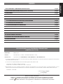 3
3
-
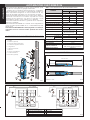 4
4
-
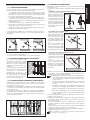 5
5
-
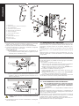 6
6
-
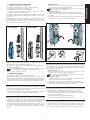 7
7
-
 8
8
-
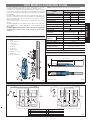 9
9
-
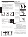 10
10
-
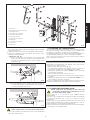 11
11
-
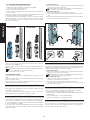 12
12
-
 13
13
-
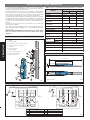 14
14
-
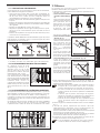 15
15
-
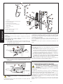 16
16
-
 17
17
-
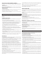 18
18
-
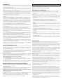 19
19
-
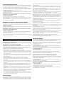 20
20
-
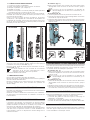 21
21
-
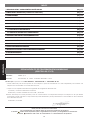 22
22
-
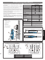 23
23
-
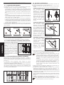 24
24
-
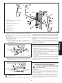 25
25
-
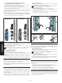 26
26
-
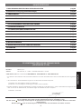 27
27
-
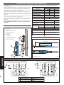 28
28
-
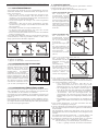 29
29
-
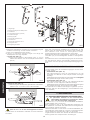 30
30
-
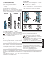 31
31
-
 32
32
-
 33
33
-
 34
34
-
 35
35
-
 36
36


Genius Euro Breeze 06 Istruzioni per l'uso
- Tipo
- Istruzioni per l'uso
in altre lingue
Documenti correlati
-
Genius Euro Breeze 06 Istruzioni per l'uso
-
-
-
-
-
-
-
-
-
