Thermo Fisher Scientific ALPS5000 Automated Plate Sealer Manuale utente
- Tipo
- Manuale utente

ALPS5000 Automated Plate Sealer
User Manual
MNLALPS5000 • Revision A • October 2020

IMPORTANT Read this instruction manual. Failure to follow the instructions in this manual can result in
damage to the unit, injury to operating personnel, and poor equipment performance.
CAUTION All internal adjustments and maintenance must be performed by qualified service personnel.
Material in this manual is for informational purposes only. The contents and the product it describes are
subject to change without notice. Thermo Fisher Scientific makes no representations or warranties with
respect to this manual. In no event shall Thermo be held liable for any damages, direct or incidental, arising
from or related to the use of this manual.
© 2020 Thermo Fisher Scientific Inc. All rights reserved.

Contents
Safety Considerations .................................................. 1
Introduction ................................................................. 2
Unpacking ALPS5000 System ................................. 2
Repositioning the Transit Plate Prior to First Use ...... 2
Installing the Magnetic Foil Guide ............................. 3
Packing List ............................................................. 4
Principle of Operation................................................... 5
Installation.................................................................... 6
Intended Use............................................................ 6
Operating Environment ................................................ 7
Connecting the Voltage Supply ................................ 7
Foil/Film Loading and Unloading .................................. 8
Standard Foils.......................................................... 8
Loading the ALPS5000 with Heat Sealing Film......... 8
Adjusting the Foil Position ........................................ 9
Operation Procedure and Optimization ........................ 10
Temperature and Time Settings ............................... 10
Commands, Indicators and Warnings....................... 10
Setting the Sealing Operation................................... 10
ALPS5000 User Interface............................................. 11
Initial Set Up............................................................. 11
Main Screen............................................................. 11
Settings.................................................................... 13
Loading/Unloading a Foil.......................................... 14

Programs ................................................................. 15
Service..................................................................... 17
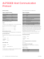
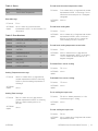
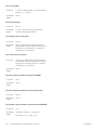
ALPS5000 Host Communication Protocol ................... 18
Specifications of ALPS5000......................................... 21
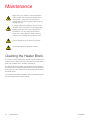
Maintenance ................................................................ 22
Cleaning the Heater Block........................................ 22
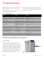
Troubleshooting........................................................... 23
Preparing ALPS5000 for Shipment........................... 23
Regulatory Information ................................................. 26
Product Safety ......................................................... 26
EMI/EMC ................................................................. 26
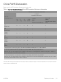
China RoHS Declaration........................................... 27
CE Declaration ......................................................... 28
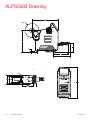
ALPS5000 Drawing ..................................................... 32
Warranty...................................................................... 33
WEEE Compliance ...................................................... 34
Contact Information .................................................... 37

ALPS5000 Safety Considerations | 1
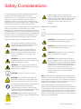
Safety Considerations
It is important that ALPS5000 is installed and operated in
compliance with all applicable Heath and Safety
requirements. It is your responsibility to ensure that you
identify and comply to all relevant Health and Safety
regulations. Failure to do so may result in damage to the
equipment and could cause personal injury. Read this guide
carefully before handling or operating this equipment.
Under no circumstances will the supplier of this equipment be
liable for any incidental, consequential or any special
damages of any kind whatsoever, including but not limited to
lost profits arising from, or in anyway connected with the use
of this equipment or this Instruction manual. If the equipment
is used in a manner not specified by the manufacturer, the
protection provided by the equipment may be impaired.
Warning Symbols Used In Accordance With IEC 417:
MAINS SWITCH SYMBOLS
I = ON
0 = OFF
Below are important safety precautions that apply to this
product:
Note: The ALPS5000 is supplied for direct connection to a
nominal 115 VAC or 240 VAC mains supply. The equipment
can be used at a minimum of 108V to account for variation in
supply when connected to nominal 115VAC, and a maximum
of 250V when connected to nominal 240VAC.
It is not recommended to use solvents to clean the unit.
Certain components become hot during the correct operation
of this equipment. These components are marked and care
should be taken to avoid personal injury. The electrical supply
must be disconnected, prior to the removal of any safety
guards. Thermo Fisher Scientific accepts no responsibility for
the misuse of this equipment.
This symbol used alone indicates important
operating instructions which reduce the risk of
injury or poor performance of the unit.
CAUTION: This symbol, in the context of a
CAUTION, indicates a potentially hazardous
situation which if not avoided could result in
minor to moderate injury or damage to the
equipment.
WARNING: This symbol indicates potentially
hazardous situations which, if not avoided, could
result in serious injury or death.
WARNING: This symbol indicates situations
where dangerous voltages exist and potential for
electrical shock is present.
CAUTION: Protective Conductor Terminal
CAUTION: HOT SURFACE/HOT AREA, This
Instrument is fitted with an internal heater with a
Maximum temperature of 199°C when in use.
This symbol indicates a need to use gloves during
the indicated procedures. If performing
decontamination procedures, use chemically
resistant gloves. Use insulated gloves for handling
samples and when using liquid nitrogen.
CAUTION: Keep hands clear during priming
process to avoid risk of finger entanglement and
entrapment.
Before installing, using or maintaining this
product, please be sure to read this manual and
product warning labels carefully. Failure to follow
these instructions may cause this product to
malfunction, which could result in injury or
damage.
WARNING: Do not operate this instrument in an
atmosphere containing explosive gases.
WARNING: Only approved supplied mains cord
set must be used with this instrument.
WARNING: If it is required to use an extension
lead, the lead MUST be earthed.
CAUTION: Safety guards must be used at all
times of operation of the unit. At no time should
the sealing film be in place whilst the unit is being
transported.The ALPS5000 is designed to be
operated with a maximum sealing temperature of
199°C. This unit should be switched on 10
minutes prior to use to reach the set temperature.
This unit should only be used in a suitable
ventilated area.

2 | Introduction ALPS5000
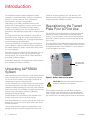
Introduction
The ALPS5000 System has been designed for robotic
integration, or stand alone sealing, offering a fast effective
solution for the heat-sealing of micro well plates for
experimentation, storage or transportation.
Heat sealing is now widely considered to be the most
effective way of sealing plates for assays, thermal cyclers,
storage and shipping. The extensive range of sealing
materials now available for our new instrument, gives a
permanent or peel-able high integrity seal for all plate material
types.
The range includes ultra clear materials for colorimetric or
fluorimetric assays, along with solvent resistant seals with
exceptional low temperature (-80° C) storage characteristics
and a breathable gas permeable seal.
The new ALPS5000 has a compact footprint saving bench
space. It features a serial port allowing RS232 and external
foot switch operation for robotic control and a touch screen
for manual operation.
Both seal time and temperature are fully adjustable. The unit
has built-in sensors to monitor and provide error output
warning signals. The unit produces no waste material and
seals plates of different heights.
ALPS5000 is designed to be integrated into robotic platforms
from all leading automation companies.
Unpacking ALPS5000
System
When unpacking your ALPS5000 unit, visually inspect the unit
for any damage which may have occurred during shipping.
Do not use the unit if there is any damage. Check that all
components are present. See packing list.
The unit is supplied in a re-usable crate and a transit bracket
that must be retained in case the unit requires servicing. To
reposition the transit bracket prior to first use, follow the steps
given in the manual. The ALPS5000 is a fragile instrument and
requires proper packaging for shipping. Inadequate
packaging can lead to damage.
Use appropriate PPE and necessary tools available in the
facility to remove the unit from the crate properly.
Once the ALPS5000 is on a bench, open the door using a flat
screw driver. Cut and remove the zip tie used to secure the
foil feed mechanism.
Thermo Fisher Scientific accepts no responsibility for any
damage incurred during return shipping unless the unit is
packed in the same packaging as it was delivered. This
equipment must be lifted using the appropriate lifting and
carrying equipment available in the facility.
Repositioning the Transit
Plate Prior to First Use
The ALPS5000 comes shipped with a transit plate installed
internally to protect the instrument from damage during
shipping. The transit plate is used to secure the internal foil
guide with a cable tie as well as to prevent the plate shuttle
from moving.
The transit plate must be retained should the instrument need
to be shipped in the future. The transit plate is easily removed
and repositioned within the ALPS5000 for normal operation
via the provided thumb screws.
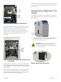
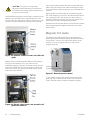
Figure 1. Unlock front service panel
Use flat bladed screwdriver or similar object, rotate slot
screw, located on the ALPS5000 door, approximately 90°
CCW. This will unlock and drop down front service panel to
gain access to the main sealing area and front of the machine.
CAUTION: Machine should be switched off and
all power removed from the system.
Turn 90° using a
flat bladed screw
driver

ALPS5000 Introduction | 3
Figure 2. Remove Transit plate and Cable Tie
Cut the exposed cable tie and remove from the unit. If the
cable tie (or a portion of the cable tie) falls into the unit, cut it
carefully and remove from the unit prior to operation.
The transit plate is secured onto the ALPS5000 with two
thumb screws. Unscrew and remove the screws and use
caution to not drop the transit plate onto or into the
ALPS5000.
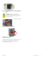
Figure 3. Vertically Flipped and Repositioned
Transit Plate
Vertically rotate the transit plate so that the back side of the
plate is facing forward. The caution symbols should be visible
and the cable tie hole should be higher and to the right side of
the ALPS5000.
With the transit plate repositioned, use the lower holes in the
plate to attach the transit plate back to the ALPS5000. Be
sure to finger tighten the thumb screws so that the plate or
screws do not come loose during operation.
Raise the front service panel back in to place and turn the slot
screw approximately 90 degrees clockwise to secure the
panel in place.
Installing the Magnetic Foil
Guide
The Magnetic Foil Guide must be installed onto its platform
and correctly aligned prior to use, and for proper function of
the ALPS5000.
1. To access the Magnetic Foil Guide platform via the side
service panel, use a 2.5 mm Allen key (provided) to
remove the 4 screws as shown.
Figure 4. Removal of service panel
CAUTION: This panel is not interlocked.
Machine should be switched off and all power
removed from the system before gaining access
to side service panel.
Remove 4 screws using
2.5mm Allen keys provided

4 | Introduction ALPS5000
Figure 5. Service panel to access magnetic foil
guide
Figure 6. Aligning magnetic foil guide with
receiving holes on the platform
2. Hold the finger tab on the Magnetic Foil Guide. Ensure
the white reflector is facing up and the long flat edge
faces towards the rear of the ALPS5000. Lower the
Magnetic Foil Guide down onto the platform.
3. Ensure that both location dowels at either end of the
Magnetic Foil Guide must align with the receiving holes
on the platform. The magnet will secure the Foil Guide in
place if positioned correctly.
Figure 7. Fin Alignment
4. Check that the three metal fins on the foil guide align
exactly with the corresponding fins on the platform. If
they are misaligned, lift the foil guide up using the finger
tab and attach again.
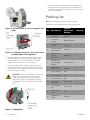
Packing List
Note: This packing list includes re-order numbers.
Check that your package contains the following items:
CAUTION: The foil trimming blade is hazardously
sharp. Do not extend any part of your hand
farther than necessary into the ALPS5000 to
place the foil guide onto its platform. HANDLE
THE MAGNET FOIL GUIDE WITH THE FINGER
TAB.
No. Description
Thermo
Fisher Part
Number
Quantity
1ALPS5000 AB-5000 1
2Instruction
manual MNLALPS5000 1
3Plate locators
set of 3 AB5-067 1
4Communication
lead 4 metre AB5-P311 1
5
Foil Spool w/
Clutch
Assembly
AB5-A020 1
6
96 Well PCR
Plate Support
Adapter
AB-0563/1000 1
7Excess Foil
Removal Tool AB5-094 1
8mains lead U.K N/A 1
9mains lead U.S N/A 1
10 E.U. mains lead N/A 1
11 5 Amp anti-
surge fuse 5050-10010 2
12 2.5 mm Allen
key 2022-10008 1
13 Mains Lead
China N/A 1
14 Magnetic Foil
Guide AB5-A007 1

ALPS5000 Principle of Operation | 5
Principle of Operation
The unsealed plate is placed on a shuttle which extends from
the front of the sealer, allowing full access with a robotic arm
or stacking system. The shuttle is drawn into the unit
automatically. The plate sealing operation will vary based on
user settings & set sealing time. The shuttle thereafter returns
the shuttle and the plate to its original start position.
The sealer can operate as a part of an automated system or in
stand alone mode. Each roll of sealing film is sufficient for
approximately five thousand plates. The cutting system cuts
the film to cover the entire plate surface with a variable total
length of 119 mm-128 mm allowing peelable or automation
compatible applications. See Figure 8 below.
The rolls of sealing film are either aluminum or clear laminates
and are able to produce permanent, pierce-able or peel-able
seals with polypropylene, polystyrene, polythene or COC
plates.
To keep the size and weight to a minimum, the unit is fully
electronic and all parameters such as temperature and time
are fully adjustable to ensure a perfect, even seal with different
plates and film formats.
User safety has been carefully considered during the design
process to eliminate risk of contact with hot surfaces or the
internal mechanism during operation.
Figure 8. 384 Well Sealed Plate.

6 | Installation ALPS5000
Installation
The machine should be installed on a sturdy bench to avoid
any vibration during operation. When locating the machine,
there should be enough space allowed for the shuttle to move
out without hitting anything or anybody.
The reduced weight compared to the previous model does
make the ALPS5000 much easier to move into a suitable
position.
Intended Use
ALPS5000 Plate Sealer is intended to be used for the heat-
sealing of microplates during experimentation, storage or
transportation. This device is not intended to be used as a
Medical Device.
CAUTION: Use appropriate lifting and carrying
equipment available in the facility during unit
movement from one place to another place. Also
use any necessary PPE during unit movement.

ALPS5000 Operating Environment | 7
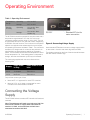
Operating Environment
The ALPS5000 should be operated in an environment with a
temperature range between 15°C and 40°C and a non-
condensing relative humidity range of 10% to 80%. The unit
should be kept at least 4" from the side of walls, neighboring
ALPS5000 units and furniture. The unit should not be placed
adjacent to equipment that radiates heat that could impact
the operating environment as listed in Table 1. The unit should
be kept out of draught and air currents as they will have an
adverse effect on the temperature stability of the sealing
platen. The ALPS5000 will not seal if the temperature is not at
the set temperature. So, if the sealing platen is subjected to
draught, then the time between cycles may be increased.
The mains plug supplied with this unit is fitted with the
following fuse:
Only refit the correct type of fuse.
• Must be IEC 127 approved for use in EEC countries.
• Must be C.S.A. or UL listed or recognized for use in
Canada or the United States of America.
Connecting the Voltage
Supply
The ALPS5000 utilizes a standard IEC inlet which is fused and
switched.
Note: The equipment will work at a minimum of 108 V to
account for variation in supply when connected to
nominal 115 VAC, and a maximum of 250 V when
connected to nominal 240 VAC.
Figure 9. Connecting Voltage Supply
Insert standard IEE lead and connect to voltage supply switch
on the rocker I=0 switch and check all guards are fitted.
The displays mounted on the front of the unit should illuminate
with the Thermo Scientific logo.
Table 1. Operating Environment
Temperature
Range
Operating
Storage
15°C to 40°C
20°C to 40°C
Relative
Humidity
Operating
Storage
10% to 80% Non
condensing
10% to 80% Non-
condensing
Supply Fuses fitted
in Plug
Fuses fitted in rear
inlet
230 V 13 Ampere T5AH 250 V
115 V No Fuses T5AH 250 V
RS 232 Standard IEC inlet for
mains connection

8 | Foil/Film Loading and Unloading ALPS5000
Foil/Film Loading and Unloading
Standard Foils
The different types of foils that can be used include the Easy
Peel, Clear Seal, Easy Pierce, and Easy Pierce Strong Foil
Heat Seals.
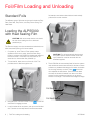
Loading the ALPS5000
with Heat Sealing Film
The Electrical supply must be connected and switched on to
allow automated priming of foil once loaded.
1. On power up, once Thermo Fisher splash screen
appears and the unit is ready, press the Start Setup
button to continue. ALPS5000 will initialize and default to
the home screen. The screen may stay blank for 30
seconds to a minute when first powered up.
2. To load the foil, allow one turn of the roll of foil. This
provides slack to feed through the unit.
3. Navigate to the “Foil load” screen. Press to start the
automatic foil engage process.
4. Loop foil under tie bar as shown, and up into the foil feed
slot. Continue to manually feed foil until the automated
foil retention mechanism takes hold and mechanically
pulls the foil into the machine.
5. The ALPS5000 will automatically feed foil into the system
until the internal sensors are reached. It will then continue
to feed on a predetermined length of foil which is suitable
for trimming and easy to reach. Press which has
now replaced the load button. Once the foil has been
trimmed, the shuttle will extend from the unit to allow
access into the machine and permits you to remove
excess cut off length. This will ensure a straight first edge.
CAUTION: We recommend that the unit should
be cool when loading the film to eliminate
possible injury.
CAUTION: Film will automatically feed through
the system and the waste trimmed via the trim
cycle, waste film must be removed with the
tweezers supplied.
Foil feed slot
Foil feed tie bar

ALPS5000 Foil/Film Loading and Unloading | 9
6. Once the excess piece of foil has been removed from the
machine, press Done to proceed as prompted. The unit
will now prime itself ready for the first use.
7. To unload foil at any time, navigate to the Load Foil
Screen and press . Foil will feed out from back of
machine.
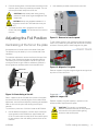
Adjusting the Foil Position
Centralizing of the foil on the plate
As supplied, the foil is set to be in the center of the plate.
The position may be varied by 2 mm on either side of the
centerline.
To make this adjustment, remove the foil and foil spool from
the rear of the machine and loosen the stainless steel nut.
This allows you to move the plastic nuts left to right, thus
moving the foil left to right. When a satisfactory position is
found, tighten the stainless steel nut and reload the foil.
Figure 10. Centralizing of the foil
Seal 3-4 plates to let the foil settle in the center of the plate
and check if the foil is centrally aligned. If this needs further
adjustment, remove foil and adjust by loosening the stainless
steel nut from the foil spool and winding the foil spool
centrally.
To remove any miss cuts of foil from inside the ALPS5000:
• Use flat bladed screwdriver or similar object, rotate slot
screw located on ALPS5000 door approximately 90°
CCW. This will unlock and drop down front service panel
to gain access to the main sealing area and front of the
machine.
• Use tweezers provided to remove any miss cuts.
Figure 11. Removal of service panel
To gain further access to the machine via side service panel,
use a 2.5 mm Allen key (provided) and remove the 4 screws
as shown. Remove panel to reveal magnetic foil guide.
Figure 12. Magnetic Foil guide
Remove magnetic foil guide using the finger tab and get rid of
any sliver or miss cuts of foil.
Figure 13. Finger Tab
Replace magnetic foil guide squarely in position on two
location dowels. Replace service panel.
CAUTION: Keep hands clear during priming
process to avoid risk of finger entanglement and
entrapment.
CAUTION: Always use supplied tweezers if it is
required to remove foil.The heater block may be
HOT.
Plastic Nut
Stainless Steel Nut
Fine Pitch Thread
CAUTION: This panel is not interlocked.
Machine should be switched off and all power
removed from the system before gaining
access to side service panel.
Remove 4 screws using
2.5mm Allen key provided

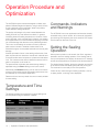
10 | Operation Procedure and Optimization ALPS5000
Operation Procedure and
Optimization
The ALPS5000 system has been designed to reliably seal
plates of different heights and plastics, using a variety of films,
to give a seal with varying properties, these components
require different sealing conditions.
The quality and strength of the seal created between the
sealing films will vary with different conditions. In general,
increasing either the sealing temperature or duration of seal,
gives a stronger, more complete seal. However, over-sealing
on a regular basis is not recommended as applying more heat
can cause damage and distortion to the plate being sealed.
This in turn would reduce the number of times a particular
plate can be re-sealed. Therefore a balance has to be
achieved that gives an acceptable seal with the minimal plate
damage.
Another optimization factor is the sealing surface area of the
plate. A plate with thin raised rims around each tube will have
a reduced surface area compared to a plate with wide raised
rims. This means that less heat is needed to seal the thin rim
plate in comparison to the wide rim.
The pressure that the heater plate exerts during sealing is
adjustable using the Force setting on the home screen.
Alternatively the Distance setting can be used to control the
amount of downward travel the heat sealing plate moves from
the detected top of the plate independent.
Plates that do not have any raised rims are not usually suitable
for heat-sealing.
Temperature and Time
Settings
The following table gives a guide line of typical sealing time
and temperature range for different materials.
Commands, Indicators
and Warnings
The ALPS5000 runs on an application software that is easily
accessible using a touch screen. All commands, indications
and warnings are relayed by the touch sensitive LCD Display
Panel located on the front of the unit.
Setting the Sealing
Operation
With a plate in position on the shuttle, the ‘Start’ segment is
pressed to start the sealing operation. If the sealing plate is
not up to temperature, the display will show that it is ‘Heating’
and the actual temperature compared to the set temperature.
The display flashes ‘Sealing’ during the operation and returns
to the Home screen after sealing the plate and priming foil.
The instrument is now ready for the next operation.
If there are any issues during the sealing operation, such as
no plate present, a warning will be displayed.
Plate
Material
Temperature
Setting Time Setting
Polystyrene 145°C - 165°C 1.0 Seconds -
3.0 Seconds
Polypropylene 150°C - 175°C 1.0 Seconds -
3.0 Seconds
Polyethylene 150°C - 170°C 1.0 Seconds -
3.0 Seconds

ALPS5000 ALPS5000 User Interface | 11
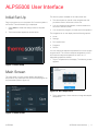
ALPS5000 User Interface
Initial Set Up
Plug in the system to turn the power ON. Once the system is
turned ON, ThermoScientific logo is displayed.
1. Select Start to initiate the setup process of the plate
sealer.
2. The Home screen appears as shown below.
Figure 14. Start Setup
Main Screen
The main screen or home screen displays the setpoint
temperature, time and distance or force of the set program on
the plate sealer (Refer to figure 15).
Figure 15. Main Screen
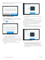
The various options available on the main screen are:
• The vertical panel on the left is the navigation bar that
provides access to all functions of the unit.
• You can change the temperature, time and distance or
force from the main screen.
• You can start the program you have set for the operation.
The navigation bar on the display has the following options:
•Home
• Settings
• Foil Load/Unload
•Programs
•Service
You can change the setpoint temperature from Home screen
as given below. The minimum setpoint temperature is 35°C
and maximum setpoint temperature is 199°C at 1°C
adjustable temperature interval.
1. Tap on Temperature on the display. The following screen
appears.
Figure 16. Set Temperature
2. Tap or press the up / down arrows to change the setpoint
temperature.

12 | ALPS5000 User Interface ALPS5000
Note: If you close the window without saving the changes,
you will receive the following screen:
Figure 17. Unsaved Changes
Select Discard Changes if you do not wish to save the
changes. Select Save Changes if you wish to confirm the
changes you made.
3. Press to confirm the changes.
Figure 18. Settings Saved Confirmation
4. Click OK. You will receive a confirmation message that
your settings have been changed.
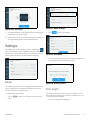
To change the setpoint time on the Home screen, follow the
steps given below. The minimum time interval is 0.5 seconds
and maximum time interval is 9.9 seconds. The time interval
can be adjustable in 0.1 second intervals.
1. Tap on Time on the display. The following screen
appears.
Figure 19. Set Time
2. Change the setpoint time by tapping or pressing the up /
down arrows.
3. Repeat step 3 and step 4 from the previous procedure to
save the desired setpoint time.
To change the setpoint mode (Distance/Force depending on
the mode the unit is set to) on the Home screen, follow the
steps given below. The minimum sealing distance is
10 μm and maximum sealing distance is 50 μm with
increments of 1 μm.
1. If you wish to set Distance as setpoint mode, tap on
Distance on the display. The following screen appears:
Figure 20 a. Set Distance
2. If you wish to set Force as setpoint mode, tap on Force
on the display. The following screen appears. The
minimum sealing force you can apply is 5 kg and
maximum sealing force is 50 kg with adjustable force of 1
kg increments. This setting may need to be re-entered if
the unit loses power.

ALPS5000 ALPS5000 User Interface | 13
Figure 20 b . Set Force
3. Change the setpoint mode (distance/force) by tapping or
pressing the up / down arrows.
4. Repeat step 3 and step 4 from the previous procedure to
save the desired setpoint mode (distance/force).
Settings
The second tab on the navigation panel is the Settings
icon. The following screen is displayed when you select the
Settings icon. This screen allows you to configure or edit the
type of mode, foil length, and sleep after time interval.
Mode
The mode settings allows you to toggle between Distance or
Force. The distance is measured in Micrometer (μm) and
Force is measured in Kilograms (Kg).
To change the mode settings:
1. Tap on to select Force/Distance from the drop
down.
Figure 21. Mode Settings
2. Click to save your settings.
Figure 22. Save Mode
3. You will receive the following confirmation message that
your settings have been saved. Click OK.
Figure 23. Settings Saved
Foil Length
The foil length allows to set a minimum foil length 119 mm
and a maximum foil length of 128 mm in increments of 1 mm.
To set the desired foil length:
1. Tap on Foil Length from Settings.

14 | ALPS5000 User Interface ALPS5000
2. Select the length of the foil.
3. Click . You will receive a confirmation message
that your settings have been saved.
4. Click OK. The foil length is configured.
Sleep after
Sleep after is the idle time out that the unit is unattended. This
allows you to set time duration for the unit to go into sleep
mode due to the unproductive time that a unit is not being
used. The minimum sleep after time you can set is for 1 hour
and the maximum time for the unit to be in sleep after mode is
24 hours. To set or change the sleep after time:
1. Tap on to configure the sleep after time.
2. Select the duration that you wish to configure. Select
duration that you wish to configure, a value of 0 will
disable the sleep feature.
3. Click . You will receive a confirmation message
that your settings have been saved.
4. Click OK. The sleep after time is set.
Eco Mode
The Eco mode is a power saver setting that allows the user to
set a time (in hours) for the system to be active. The system
goes into sleep mode after the selected time expires.
The heater will reduce to a set temperature to save electricity.
Select Wake or any navigation button on the left to return to
the home page. This setting may need to be re-entered if the
unit loses power
Figure 24. Eco Mode
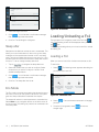
Loading/Unloading a Foil
The third tab on the navigation panel is the Foil Load
icon. The following screen will be displayed when you select
the icon.
The loading/unloading allows you to load a new foil or unload
an existing foil.
Loading a Foil
When you want to load a foil, the instrument senses no foil.
To load a foil:
1. Select . The following screen appears describing the
process to load a new foil:
Figure 25. Load New Foil
2. Select . The machine starts automatic foil engage
process.
3. Once the foil is ingested, select to ensure a
straight edge.

ALPS5000 ALPS5000 User Interface | 15
Figure 26. Trim Foil
4. Remove the trimmed section of foil and select .
Dispose the trimmed edge.
Figure 27. Removal and disposal of trimmed edge
When you want to unload a foil, press to eject the
foil. Machine ejects foil and displays load page.
Figure 28. Unload Foil
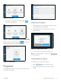
Programs
The programs tab allows you to view, edit and create the load
parameters of a program.
Viewing a Program
1. Select Programs from the navigation menu and a list of
configured programs are displayed.
2. Select the eye icon for a quick program view of the
program details.
Figure 29. Program Quick View
3. You may load or edit the program as required.
Note: If there are no programs created, click
to create a program.
Create New Program
This enables you to create a new program.
1. Select on the Programs screen.
2. Tap on the Name field to enter the name using the
keypad.

16 | ALPS5000 User Interface ALPS5000
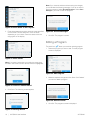
Figure 30. Enter Name of the Program
3. Enter the temperature and time within the range specified
on the screen. Choose distance or force as mode
depending on your choice. Enter the values within the
range given on the display.
Figure 31. Enter Values
Note: If you enter a value that is not within the range given,
the field in which the incorrect value is entered is highlighted.
Figure 32. Incorrect Value Entered
4. Click Save. The following screen appears.
Figure 33. Settings Saved
Note: If you close the window without saving the changes,
you will receive the following message. If you do not wish to
save the programs, select Discard Changes. Select Save
Changes if you wish to save the program.
Figure 34. Unsaved Changes
5. Click OK. The program is saved.
Editing a Program
The pencil icon allows you to edit an existing program.
1. Select the program you want to edit. The edit program
screen is displayed.
Figure 35. Edit Program
2. Make the required changes and click Save. Click Delete if
you want to delete a program.
Figure 36. Delete Confirm
3. Click OK. The programs screen is displayed.
La pagina si sta caricando...
La pagina si sta caricando...
La pagina si sta caricando...
La pagina si sta caricando...
La pagina si sta caricando...
La pagina si sta caricando...
La pagina si sta caricando...
La pagina si sta caricando...
La pagina si sta caricando...
La pagina si sta caricando...
La pagina si sta caricando...
La pagina si sta caricando...
La pagina si sta caricando...
La pagina si sta caricando...
La pagina si sta caricando...
La pagina si sta caricando...
La pagina si sta caricando...
La pagina si sta caricando...
La pagina si sta caricando...
-
 1
1
-
 2
2
-
 3
3
-
 4
4
-
 5
5
-
 6
6
-
 7
7
-
 8
8
-
 9
9
-
 10
10
-
 11
11
-
 12
12
-
 13
13
-
 14
14
-
 15
15
-
 16
16
-
 17
17
-
 18
18
-
 19
19
-
 20
20
-
 21
21
-
 22
22
-
 23
23
-
 24
24
-
 25
25
-
 26
26
-
 27
27
-
 28
28
-
 29
29
-
 30
30
-
 31
31
-
 32
32
-
 33
33
-
 34
34
-
 35
35
-
 36
36
-
 37
37
-
 38
38
-
 39
39


