TECHNIBEL CA8FIA0R5I Istruzioni per l'uso
- Categoria
- Condizionatori d'aria mobili
- Tipo
- Istruzioni per l'uso

EG
I
F
D
E
OPERATING INSTRUCTIONS •
ISTRUZIONI D’USO
NOTICE D’UTILISATION •
BEDIENUNGSANLEITUNG
INSTRUCCIONES DE USO
37.4254.033.01 10/2010
Split air conditioner system •
Condizionatore d’aria split system
Climatiseurs split •
Split-klimagerät
Acondicionador de aire de consola partida sistema split •
ΔΙΑΙΡΟΥΜΕΝΕΣ ΜΟΝΑΔΕΣ ΚΛΙΜΑΣΜΟΥ
MTA8FIA0R5I--
MTA8FBI0R5I--
KPA8FIA0R5I--
CA8FIA0R5I--
SDA8FIA0R5I--
MONO SPLIT
MTAFIA0R5I--
MTAFBI0R5I--
MULTI SPLIT
MONO/MULTI SPLIT
MONO/MULTI SPLIT
MONO/MULTI SPLIT

The following symbols used in this manual, alert you to
potentially dangerous conditions to users, service personnel
or the appliance:
This symbol refers to a hazard or unsafe practice which
can result in severe personal injury or death.
This symbol refers to a hazard or unsafe practice which
can result in personal injury or product or property damage.
This air conditioner is equipped with cooling, drying, heating and fan only functions.
Details on these functions are provided below; refer on these descriptions when using the air conditioner.
CONTENTS
2
NAME OF PARTS AND OPERATION SELECTOR SWITCH 3
INSTALLATION LOCATION 5
ELECTRICAL REQUIREMENTS 5
SAFETY INSTRUCTIONS 5
USING THE REMOTE CONTROL UNIT 5
REMOTE CONTROL UNIT 6
HOW TO SET THE PRESENT TIME 7
COOLING 7
HEATING 7
AUTOMATIC OPERATION 7
DEHUMIDIFYING (DRY) 7
FAN ONLY 8
ADJUSTING THE FAN SPEED 8
FILTER Ti0
2
8
NIGHT MODE/ENERGY SAVING 8
HIGH POWER MODE 8
SETTING THE TIMER 9
SETTING THE 1 HOUR TIMER 9
ADJUSTING THE AIR FLOW DIRECTION 9
OPERATION WITHOUT THE REMOTE CONTROL UNIT 11
CARE AND CLEANING 11
TIPS FOR ENERGY SAVING 13
TROUBLESHOOTING 14
DECLARATION OF CONFORMITY
This product is marked as it satisfies Directives:
– Low voltage no. 2006/95/CE.
– Electromagnetic Compatibility no. 89/336 EEC, 92/31 EEC and 93/68 EEC.
This declaration will become void in case of misusage and/or from non observance though partial of Manufacturer's
installation and/or operating instructions.
NOTE
PRODUCT INFORMATION
If you have problems or questions concerning your Air
Conditioner, you will need the following information. Model
and serial numbers are on the nameplate on the bottom of
the cabinet.
Model No.
Serial No.
Date of purchase
Dealer’s address
Phone number
ALERT SYMBOLS
EG
WARNING
CAUTION
INFORMATION FOR CORRECT DISPOSAL OF THE PRODUCT IN ACCORDANCE WITH THE EUROPEAN
DIRECTIVE 2002/96/EC
At the end of its working life this equipment must not be disposed of as an household waste.
It must be taken to special local community waste collection centres or to a dealer providing this service.
Disposing of an electrical and electronic equipment and its batteries separately avoids possible negative effects on the
environment and human health deriving from an inappropriate disposal and enables its components to be recovered
and recycled to obtain significant savings in energy and resources.
In order to underline the duty to dispose of this equipment and batteries separately, the product is marked with a
crossed-out dustbin.

3
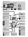
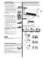
NAME OF PARTS AND OPERATION SELECTOR SWITCH
EG
NOTES
● It is possible to set the air conditioner in order to let
the OPERATION, TIMER and STANDBY lamps always
OFF, even during operation.
Press contemporary the IFEEL and FAN buttons on
the remote control unit for more then 5 seconds.
Repeat the same procedure to set again the normal
operation conditions.
● In case of troubleshooting the air conditioner
diagnostic system activates the lamps accordingly,
even if they are set to OFF. See paragraph
TROUBLESHOOTING for further details.
6
2
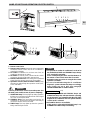
1. Remote control unit.
2. Remote control sensor: Detects the room temperature
around the remote control unit, the air conditioner is
controlled accordingly.
3. Air outlet: Conditioned air is blown out of the air
conditioner through the air outlet.
4.
Air intake: Air from the room is drawn into this section
and passes through air filter which removes dust.
5. Remote control receiver: This section picks up infrared
signals from the remote control unit (Transmitter).
6. Operation selector (without remote control): Push
the button to walk through the operation modes (OFF,
COOL and HEAT)
7. OPERATION lamp: This lamp lights up during operation.
It blinks once to announce that the remote control signal
has been received and stored.
8. STANDBY lamp: This lamp lights up when the air
conditioner is connected to the power and ready to
receive the remote control command.
9. TIMER lamp: This lamp lights up when the system is
being controlled by the timer.
The OFF position does not disconnect the power. Use
the main power switch to turn off power completely.
WARNING
7
89
5
3
4
2
1
6
1
MULTI SPLIT
● The blinking of TIMER and STANDBY lamps and
OPERATION lamp ON, indicates that the operating
mode selected is not compatible with the unit. If this
happen the air conditioner does not operate until the
correct mode is selected.
● AUTOMATIC Mode is not available.
If this mode is selected OPERATION lamp is on,
STANDBY and TIMER lamps are blinking.
only
3
99
7
78 5
4

EG
4
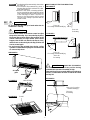
NOTES
● It is possible to set the air conditioner in order to let
the OPERATION, TIMER and STANDBY lamps always
OFF, even during operation.
Press contemporary the IFEEL and FAN buttons on
the remote control unit for more then 5 seconds.
Repeat the same procedure to set again the normal
operation conditions.
● In case of troubleshooting the air conditioner
diagnostic system activates the lamps accordingly,
even if they are set to OFF. See paragraph
TROUBLESHOOTING for further details.
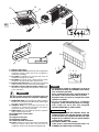
1. Remote control unit.
2. Remote control sensor: Detects the room temperature
around the remote control unit, the air conditioner is
controlled accordingly.
3. Air outlet: Conditioned air is blown out of the air
conditioner through the air outlet.
4.
Air intake: Air from the room is drawn into this section
and passes through air filter which removes dust.
5. Remote control receiver: This section picks up infrared
signals from the remote control unit (Transmitter).
6. Operation selector (without remote control): Push
the button to walk through the operation modes (OFF,
COOL and HEAT)
7. OPERATION lamp: This lamp lights up during operation.
It blinks once to announce that the remote control signal
has been received and stored.
8. STANDBY lamp: This lamp lights up when the air
conditioner is connected to the power and ready to
receive the remote control command.
9. TIMER lamp: This lamp lights up when the system is
being controlled by the timer.
10.Air intake latch, on two sides.
11.Air filter.
12.Suspension brackets.
13.Refrigerant couplings.
14.Condensate drain connection.
15.Sensor: Detects the room temperature around the unit;
when the remote control unit is not active the air
conditioner will be set by the detected temperature.
The OFF position does not disconnect the power. Use
the main power switch to turn off power completely.
WARNING
3
12
14
5
13
798
5
6
15
10
11
4
2
1
3
5
6
7
8
9
11
MULTI SPLIT
● The blinking of TIMER and STANDBY lamps and
OPERATION lamp ON, indicates that the operating
mode selected is not compatible with the unit. If this
happen the air conditioner does not operate until the
correct mode is selected.
● AUTOMATIC MODE is not available.
If this mode is selected OPERATION lamp is on,
STANDBY and TIMER lamps are blinking.
only
2
1

5
EG
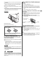
HOW TO INSTALL BATTERIES
● Remove trhe lid in the rear part of the remote control unit
and check the settings of the four microswitches as
shown below:
TEMPERATURE SENSOR SELECTOR
●
Under normal conditions the room temperature is detected
and checked by the temperature sensor placed in the
remote controller (I FEEL icon displayed ).This function
is designed to provide a confortable room temperature by
transmitting the temperature control command from the
location next to you. Therefore, when using this function,
the remote control should always be pointed at the air
conditioner.
●
It is possible to disable the remote controller room sensor
pressing the I FEEL button. In this case the I FEEL icon
on the remote controller display lights off and the sensor
placed in the air conditioner becomes active.
USING THE REMOTE CONTROL UNIT
●
Insert two AAA alkaline batteries of 1,5 V-DC making
sure that point in the direction marked in the battery
compartment.The displayed time flashes.
Press the SEL TYPE button.
Remote controller is now ready for operation.
●
The batteries last about six months. Depending on how
much you use the remote control unit.
Remove the batteries if you do not use the remote control
unit for more than one month.
Replace the batteries when the remote control unit lamp
fails to light, or when the air conditioner does not receive
the remote control unit signals.
●
The batteries of the remote control contain polluted
substances. Exhausted batteries must be disposed
according to the laws in force.
OPERATION WITH THE REMOTE CONTROL UNIT
When using the remote control unit, always point the unit
transmitter head directly at the air conditioner receiver.
HOW TO TURN ON THE AIR CONDITIONER
Press the ON/OFF button to turn the air conditioner on.
The operation lamp will light up, indicating the unit is in
operation.
The remote control unit sends the temperature signal
at any key pressing and automatically every five
minutes. If, due to some troubles, the signal from the
remote control is no longer detected, the air conditioner
keeps operating using the temperature sensor of the
indoor unit to control the room temperature. In this
case, the temperature around the remote control unit
may differ from the temperature detected in the air
conditioner position.
NOTE
SWITCHES
Set unit A or B with Remote Control (see procedure in
Installation Manual of Outdoor Unit.
NOTE
MULTI SPLIT
SAFETY INSTRUCTIONS
●
Read this booklet carefully before using this air
conditioner. If you still have any difficulties or
problems, consult your dealer for help.
●
This air conditioner is designed to give you
comfortable room conditions. Use this only for its
intended purpose as described in this Instruction
Manual.
●
Never use or store gasoline or other flammable vapor or
liquid near the air conditioner. It is very dangerous.
●
Never install electrical equipment, which is not
protected with IPX1 protection (protection against
vertical water drop), under the unit.
●
The manufacturer assumes no responsabilities if the
safety regulations or local codes are not observed.
●
Never use the power main switch to start or stop the
air conditioner: always use the ON/OFF button on the
remote control unit or the selector switch on the unit.
●
For your safety care check periodically the conditions
of the electric supply cable; the electrical connection
of the unit is Y type with cable prepared in a special
way; in case you should notice any damage due to
usage, call the nearest After Sale Service to get the
cable replaced.
●
Do not let children play with the air conditioner.
●
Do not cool the room too much if babies or invalids
are present.
●
This air conditioner is not intended for use by persons
(including children) with reduced physical, sensory
or mental capabilities, or lack of experience and
knowledge, unless they have been given supervision
or instruction concerning use of the air conditioner
by a person responsible for their safety.
WARNING
CAUTION
INSTALLATION LOCATION
●
We recommend this air conditioner to be installed
properly by qualified installation technicians in
accordance with the installation instructions provided
with the unit.
●
Do not install this air conditioner where there are
fumes or flammable gases, or in an extremely humid
space such as a green house.
●
Do not install the air conditioner where excessively
high heat-generating objects are placed.
●
Do not install the air conditioner where the
atmosphere is extremely damp or humid (e.g.
greenhouse or laundry) it could be wetted by drops
of water (i.e. in laundries).
●
To protect the air conditioner from heavy corrosion,
avoid installing the outdoor unit where salty sea
water can splash directly onto it or in sulphurous air
near a spa.
WARNING
ELETRICAL REQUIREMENTS
●
Before installation, check that the voltage of the electric
supply in your home or office is the same as the voltage
shown on the nameplate.
●
All wiring must conform to the local electrical codes.
Consult your dealer or a qualified electrician for details.
●
Each unit must be properly grounded with a ground (or
earth) wire or through the supply wiring.
●
Wiring must be done by a qualified electrician.

EG
6
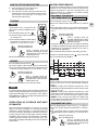
REMOTE CONTROL UNIT
TRANSMITTER
When you press the buttons of the remote
control unit, the mark
appears on the display to transmit the
setting changes to the receiver in the air
conditioner.
TIMER AND PRESENT TIME SETTING
BUTTONS
With these buttons is possible to set the
clock and the timer. For details refer to
paragraphs “ SETTING THE HOUR” and
“SETTING THE TIMER”.
“TIMER SEL” BUTTON
Press this button to select the type of
timer to activate. For details refer to
paragraph “SETTING THE TIMER”.
DISPLAY
Information is displayed when the remote controller is switched on.
If switched off, only the operating mode, the room temperature and
the clock are shown
Operation mode
Fan speed
High speed
Automatic
Medium speed
Low speed
Displayed when
transmitting data
Set point
temperature
I FEEL mode is active
(remote controller
sensor active)
Timer modes
Automatic
Cooling
Heating
Dehumidification
Fan
MODE SELECTOR BUTTON
Press this button to modify the air
conditioner mode.
(automatic) NOT AVAILABLE
FOR MULTISPLIT
When this setting is selected, the air
conditioner calculates the difference
between the thermostat setting and the
room temperature and automatically
switches to the "cool" or "heat" mode.
(heating)
The air conditioner makes the room
warmer.
(dry)
The air conditioner reduces the humidity in
the room.
(cooling)
The air conditioner makes the room cooler.
(fan)
The air conditioner works only as a
circulation fan.
Clock
Room
temperature
Night
mode
Oscillation
Flap
Filter Ti0
2
is ON
HIGH POWER
mode
TEMPERATURE SETTING BUTTONS
TEMP - (cooler)
Press this button to decrease the set
temperature.
TEMP + (warmer)
Press this button to increase the set
temperature.
SENSOR
A temperature sensor inside the remote
control unit detects the room temperature.
“SEL TYPE” BUTTON
Press this button in order to:
• set the clock
• set the ON/OFF timer
For details refer to paragraphs “SETTING
THE HOUR” and “SETTING THE TIMER”.
TEMPERATURE SENSOR SELECTOR
Press the I FEEL button to modify the
active setting for room temperature
detection (from remote controller to air
conditioner and viceversa)
“FAN “ BUTTON
Fan speed is automatically
selected by the microcomputer.
High speed.
Medium speed.
Low speed.
ON/OFF BUTTON
This button turns the air conditioner ON
and OFF.
PUSH-BUTTON FLAP
Press this button in order to select the
desired function.
Fixed: six position
Continous oscillations
Automatically oscillations
“NIGHT”/“HIGH POWER” BUTTON
Press this button in order to select the desired
mode:
NIGHT mode
HIGH POWER mode
FILTER Ti0
2
BUTTON (if present)
Press this button in order to select the mode.

7
EG
HOW TO SET THE PRESENT TIME
HEATING
1. Press the button SEL TYPE three times.
The time indication alone flashes.
2. Press the SET H button until the present time hour
is displayed. Press the SET M button until the present
time minutes are displayed. The display will
automatically stop flashing.
ONON ON
Δ 1 H Δ 1 H
MIN. MAX.
A
B
C
C
B
A
27
26
25
24
23
22
21
20
19
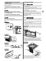
AUTOMATIC OPERATION
- NOT AVAILABLE FOR
1.Set the MODE selector to HEAT .
2.Press the ON/OFF button and switch the air condioner ON.
3.Press the TEMP. buttons to set the desired temperature (the
temperature range is between 32 °C max. and 10 °C min.).
THE DISPLAY SHOWS THE
SELECTED TEMPERATURE.
AFTER 5 SECONDS FROM THE
REQUIRED TEMPERATURE SETTING
THE DISPLAY WILL SHOW THE ROOM
TEMPERATURE AGAIN.
4.Press the FAN button to select the fan speed.
For several minutes after the start of heating operation, the
indoor fan will stop until the indoor heat exchanger coil has
warmed up sufficiently. This is because the COLD DRAFT
PREVENTION SYSTEM is operating. During this period, the
STANDBY lamp remains lit.
NOTE
DEFROSTING OF OUTDOOR UNIT HEAT
EXCHANGER
When the outdoor temperature is low, frost or ice may
appear on the heat exchanger coil, reducing the heating
performance. When this happens, a protection function for
the heat exchanger defrosting is activated. During this
function operation, the fan of the indoor unit stops and the
STANDBY lamp remains lit until defrosting is completed.
Heating operation restarts after several minutes. (This
interval will vary slightly depending on the room and outdoor
temperature).
HEATING PERFORMANCE
Aheat pump conditioner heats a room by taking heat from
outside air. The heating efficiency will fall off when the
outdoor temperature is very low. If enough heat is not
obtained with this air conditioner, use another heating
appliance in conjunction with it.
1.Set the MODE selector to AUTO .
2.Press the ON/OFF button and switch the air condioner
ON.
3.Press the TEMP. buttons to set the desired temperature
(the temperature range is between 32 °C max. and 10 °C
min.).
When this setting is selected, the air conditioner calculates
the difference between the thermostat setting and the room
temperature and automatically switches to the COOL or
HEAT mode as appropriate.
4.Press the FAN selector button to the setting you want.
THE DISPLAY SHOWS THE
SELECTED TEMPERATURE.
AFTER 5 SECONDS FROM THE
REQUIRED TEMPERATURE SETTING
THE DISPLAY WILL SHOW THE ROOM
TEMPERATURE AGAIN.
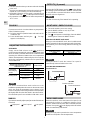
Example of operation diagram in the (Auto) mode with
the set room temperature at 23°C.
NOTE
The air conditioner changes the operation mode (from cool
to heat or vice versa, if one of the following conditions
occurs:
- ZONE A: changes if the difference between the room
temperature and the temperature set on the remote control
unit is at least 3°C..
- ZONE B: changes if the difference between the room
temperature and the temperature set on the remote control
unit is at least 1°C, one hour after the compressor stop.
- ZONE C: never changes if the difference between the
room temperature and the temperature set on the remote
control unit is no more than 1°C.
COOLING
THE DISPLAY SHOWS THE
SELECTED TEMPERATURE.
AFTER 5 SECONDS FROM THE
REQUIRED TEMPERATURE SETTING
THE DISPLAY WILL SHOW THE ROOM
TEMPERATURE AGAIN.
4.Press the FAN button to select the fan speed.
1
4
3
2
Verify that the unit is connected to the
main power and the STANDBY lamp is
light up.
1.Set the MODE selector to COOL .
2.Press the ON/OFF button and switch the
air condioner ON.
3.Press the TEMP. buttons to set the desired
temperature (the temperature range is
between 32 °C max. and 10 °C min.).
NOTE
1.Set the MODE button to DRY. The icon is displayed.
2.Press the ON/OFF button and switch the air condioner
ON.
3.Press the TEMP. buttons to set the desired temperature
(the temperature range is between 32 °C max. and 10 °C
min.).
DEHUMIDIFYING (DRY)
THE DISPLAY SHOWS THE
SELECTED TEMPERATURE.
AFTER 5 SECONDS FROM THE
REQUIRED TEMPERATURE SETTING
THE DISPLAY WILL SHOW THE ROOM
TEMPERATURE AGAIN.
MULTI SPLIT

EG
●
Use DRYoperation when you want to reduce the humidity
in the room.
●
Once the room temperature reaches the set level, the unit
repeats the cycle of turning on and off automatically.
●
During DRYoperation, the fan speed is automatically set
(Remote control lamp is ON) to prevent overcooling.
●
Dry operation is not possible if the indoor temperature is
10 °C or less.
8
ADJUSTING THE FAN SPEED
AUTOMATIC
Simply set the FAN selector to the position.A
microcomputer automatically controls the fan speed when
the AUTO mode is selected. When the air conditioner starts
operating, the difference between the room temperature
and the set temperature is detected by the microcomputer
which then automatically switches the fan speed to the
most suitable level.
NIGHT MODE / ENERGY SAVING
●
This mode enables you to save energy.
1. Set the MODE selector to cool, dry or heat.
2. Press the NIGHT button.
3. The mark appears on the display. Press the NIGHT
button again to release the NIGHT function.
What does the NIGHT mode mean?
When you select the NIGHT mode, the air conditioner will
modify automatically the set temperature after 60 minutes.
This enables you to save energy without sacrificing your
comfort.
NOTE
FAN ONLY
If you want to make air circulate without any temperature
control, follow these steps:
1. Press the ON/OFF operation button and switch the air
conditioner ON.
2. Press MODE button until only the fan sign
appears on the display.
The above mentioned data make reference to the
conditioner operating when the sensor on the remote control
unit is ON. (Refer to temperature sensor selector). If the
sensor on the indoor unit is being used then actual operation
will slightly differ from that described in the above tables.
The automatic speed is not available in FAN ONLY mode.
NOTE
WHEN DIFFERENCE BETWEEN
ROOM TEMPERATURE AND SET FAN SPEED
TEMPERATURE IS
Cooling and 2 °C and over High
dehumidifying Between 2 and 1 °C Medium
modes: Below 1 °C Low
2 °C and over High
Heating mode:
Below 2 °C Medium
High speed Med. speed Low speed
MANUAL
If you want to manually adjust speed just set the FAN selector
as desired.
OPERATING MODE SET TEMPERATURE CHANGE
Heating Lowered by 1 °C
Cooling and Dehumidifying Raised by 2 °C
During the NIGHT mode the internal fan speed is
automatically lower and reduces the noise.
NOTA
Selezione funzione
Temperatura ambiente
1 h
TEMPO
1°C
COOLING AND DEHUMIDIFYING
HEATING
Selezione funzione
Temperatura ambiente
1 h
TEMPO
2°C
HIGH POWER MODE
When this mode is active the internal fan speed is set
automatically and the air conditioner operates, for 15
minutes, at the maximum power. After 15 minutes from the
selection the symbol on the display switch off and the
mode is automatically switched off.
NOTE
During the high power operation the room temperature
could not correspond to the set temperature.
FILTER Ti0
2
(if present)
Pressing the FILTER button (symbol on the display)
the filtering system with titanium dioxide is activated; this
is very effective to prevent bad odours and to eliminate
bacteria and micro-organisms.
NOTE
The filter is active only if the internal fan is operating.
Function selection
Room temperature
TIME
Function selection
Room temperature
TIME

9
EG
ADJUSTING THE AIR FLOW DIRECTION
HORIZONTAL (manual) Only for AWI-FCI models
The horizontal air flow can be adjusted by moving the
vertical vanes to the left or right, as indicated in the following
figures.
VERTICAL (with remote control unit)
Make sure that the remote control unit has been turned on.
Press
the FLAP button to select the flap function
A)HOW TO SET THE ON TIME
1. Press the SEL TYPE button once.
The ON and time indications flash.
2. Press the SET H button until the
designed hour is displayed.
Press the SET M button until the
designed minutes are displayed. The
display will change automatically back
to show the present time after 10 sec.
3. Press the ON/OFF button to start the air
conditioner.
4. Press the TIMER SELbutton to activate
the ON timer.
B) HOW TO SET THE OFF TIME
1. Press the SEL TYPE button twice.
The OFF and time indications flash.
2. Press the SET H button until the
designed hour is displayed.
Press the SET M button until the
designed minutes are displayed. The
display will change automatically back
to show the present time after 10 sec.
3. Press the ON/OFF button to start the air
conditioner.
4. Press the TIMER SELbutton two times
to activate the OFF timer.
C) HOW TO SET A PROGRAM FOR
DAILY ON/OFF OPERATION (OR
VICEVERSA)
1. Set the timer ON/OFF as shown in A)
and B).
2. Press the ON/OFF button to start the air
conditioner.
3. Press three times the TIMER SELECT
button to activate the DAILY timer.
SETTING THE TIMER
After timer setting, press PROGRAM button in order to
check the ON/OFF setting time.
NOTE
2
1
4
3
TIMER SETTING PROCEDURE.
●
Press four times the TIMER SEL
button.The 1 HOUR TIMER mark will
appear on the display.
CANCELLATION PROCEDURE
●
Press the ON/OFF button to turn the air conditioner off.
●
Wait for the indoor unit to stop operating.
●
Press the ON/OFF button again to turn the air conditioner
on.
SETTING THE 1 HOUR TIMER
This function causes the unit to operate for one hour at the
set conditions, regardless of whether the unit is on or off.
Fixed:
six
position
Continous
oscillations
Automatically
oscillations
Left
Vertical vane
Right
Aesthetic
flap
Fuctional
flap
A
WI MODELS
FCI MODELS
VERTICAL VANE

10
Do not move the flap with your hands when the air
conditioner is running.
CAUTION
NOTES
●
The functional flap automatically closes when
the unit is off.
●
The aesthetic flap automatically closes 3
minutes after the unit is switched off. (ONLY
FOR AWI MODELS)
●
When the unit starts in heating operation,
the fan speed will be low and the flap will be
in the 4 position until the air being blown out
of the unit begins to warm. Once the air
warms up, the flap position and fan speed
change to the settings specified with the
remote control.
• Use the FLAP button on the remote control to adjust
the position of the flap. If you move the flap by hand,
the factual flap position and the flap position on the
remote control may no longer match. If this should
happen, shut off the unit, wait for the flap to close,
and then turn on the unit again; the flap position will
now be normal again.
• Do not have the flap pointed down during cooling
operation. Condensation may begin to form around the
air vent and drip down.
CAUTION
Up
Down
Flap
Air outlet
grille
ASI MODELS
FLAPS
FCI MODELS
DEFLETTORE
AWI MODELS
40°
50°
Set vertical vanes to the front position during
COOLING/DRY operation if humidity is high.
If the vertical vanes are set to the left-most or right-most
position, condensation will form around the air outlet
and drip off.
CAUTION
Zone «A»
for cooling and dehumidifyng
Zone «B»
for heating
40°
50°
«B»
«A»
«B»
«A»
(ONLY AWI- FCI MODELS)
HOW TO ADJUST THE FLAP DIRECTION
Zone «A» for cooling
and dehumidifyng
Zone «B»
for heating
A
WI MODELS
FCI MODELS
ASI MODELS
Zone «A»
for cooling and dehumidifyng
Zone «B»
for heating
EG

11
CARE AND CLEANING
●
Maintenance operations must be carried out by specially
trained personnel.
●
For safety, be sure to turn the air conditioner off and also
to disconnect the power before cleaning.
●
Do not pour water on the indoor unit to clean it. This will
damage the internal components and cause an electric
shock hazard.
WARNING
The front panel can be removed in order to wash it with
water.
CASING AND GRILLE (INDOOR UNIT)
Clean the casing and grille of the indoor unit with a vacuum
cleaner brush, or wipe them with a clean, soft cloth.
If these parts are stained, use a clean cloth moistened with
a mild liquid detergent.
When cleaning the grille, be careful not to force the vanes
out of place.
● Never use solvents, or harsh chemicals when cleaning the
indoor unit. Do not wipe the plastic casing using very hot
water.
● Some metal edges and the vanes are sharp and may
cause injury if handled improperly; be especially careful
when you clean these parts.
● The internal coil and other components of the outdoor
unit must be cleaned every year. Consult your dealer or
service centre.
CAUTION
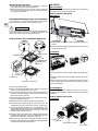
HOW TO REMOVE THE FRONT PANEL (ONLY FOR AWI-
ASI MODELS)
●
With the front panel open all the way, grip both
arms with your hans and pull toward you to remove.
●
To remount, hold the front panel roughly horizontal
and push it in until the arm shafts fit into the indenta-
tions in the main unit, then fit the front panel into place.
Front
panel
2. WHEN THE AIR CONDITIONER IS RUNNING
If you want to turn off the air conditioner push the operation
selector with a pen until the OPERATION lamp is turned off.
Power failure during operation.
In the event of power failure, the unit will stop. When the
power is resumed, the unit will restart automatically after 3
minutes.
NOTE
If you have lost the remote control unit or it has troubles,
follow the steps below.
1. WHEN THE AIR CONDITIONER IS STOPPED
If you want to turn on the air conditioner push the operation
selector with a pen to select the desired mode (COOL or
HEAT).
OPERATION WITHOUT THE REMOTE
CONTROL UNIT
The air conditioner will start in HIGH fan speed.
The temperature setting is 25°C for cooling mode and
21°C for heating mode.
NOTE
OPERATION
SELECTOR
FCI MODELS
OPERATION
SELECTOR
ASI MODELS
OPERATION
SELECTOR
A
WI MODELS
OPERATION
SELECTOR
SDI MODELS
AWI MODELS
ASI MODELS
GRILLE
STRING
●
Detach the safety string from the frame (remember to
attach it again after cleaning or maintenance).
●
Open the air intake grille
, hold it on and pull it toward
you to detach the two guides.
EG

HOW TO REMOVE THE FILTER
LATCH
SCREW
AIR INTAKE GRILLE
AIR FILTER
ASI MODELS
12
CONDENSATE
DRAIN PAN
The inspection or replacement of internal components
involve the removal of the condensate drain pan.
Some metal edges and the vanes of heat exchanger are
sharp and may cause injury if handled improperly; be
especially careful when you clean these parts.
CAUTION
HOW TO REMOVE THE CONDENSATE DRAIN PAN
RUBBER CORK
CONNECTORS
CLIPS (2)
SUPPORT
PLATE (2)
SCREW (4)
SPECIAL SCREW (4)
1.Open the air intake grille.
2.Drain the condensate water into a bucket trough the
rubber cork that should be soon closed.
3.Remove the frame-grille assembly by loosening the four
special screws with washer; you can utilise the two clips
that fix the frame to the unit.
4.Disconnect the electrical connectors between the frame-
grille assembly and the unit.
5.Remove the four screws of the two support plates.
6.Grasp the two support plates, remove with care the
condensate drain pan and clean it inside, if necessary.
7.Once finished the maintenance, reassemble the pan,
aligning the side with the hole for condensate drain and
the side with the pump; insert the connectors of the unit
into the proper hole in the pan.
8.Fix again the four screws of the support plates and the
frame group aligning the corner from which the wires exit
and the corner with the connectors of the unit.
9.Mount the air intake grille along with the filter; be sure
that the safety string has been attached and that the latch
screw has been fixed on both sides.
ADDITIONAL MAINTENANCE (ONLY FOR ASI MODELS)
Washing the grille with water
●
Clean the grille gently using a soft sponge, or the like.
Then wipe away any remaining moisture.
●
Neutral detergent may be used to remove stubborn
dirt. Then rinse thoroughly with water and wipe away
any remaining moisture.
AIR FILTER
The filter behind thefront panel should be checked and
cleaned at least once every two weeks.
HOW TO REMOVE THE FILTER
1. Grasp both ends of the front panel and pull it towards you
and up.
2. Push the filter up slightly, and then take it out. Clean the
air filter and replace it.
Front panel
Air filter
AWI-FCI MODELS
1.Grasp both ends of the air intake grille and pull to open
it.
2.Hold the air filter by the tab and pull it upward. Clean the
air filter.
3.When replacing the filter, make sure that the FRONT
mark is facing you. Reinsert the filter into place and close
the air intake grille.
2
1
FCI MODELS
FRONT
3
The air filter should be cleaned at least once every six
months or more frequently; it depends on the real operation
conditions.
ASI-SDI MODELS
EG
AWI MODELS

13
TIPS FOR ENERGY SAVING
DO NOT:
●
Block the air intake and outlet of the unit.
If they are obstructed, the unit will not work well, and
may be damaged.
●
Let direct sunlight into the room. Use sunshades,
blind or curtain.
DO:
●
Always try to keep the air filter clean. A clogged filter
will impair the performance of the unit.
●
To prevent conditioned air from escaping, keep windows,
doors and any other openings closed.
FILTER CLEANING
Use a vacuum cleaner to remove light dust. If there is
sticky dust on the filter, wash the filter in lukewarm, soapy
water, rinse it in clean water, and dry it.
1.Remove the screw on each side out of the latch using a
screwdriver.
2.Press on the two latches of the air intake grille with your
thumbs in the direction of the arrow to open the grille.
3.Open the air intake grille downward.
4.Remove the air filter from the air intake grille. Clean the
air filter.
5.Insert the filter correctly again inside the grille, close the
grille letting the latches slide toward the outside and fix
again the latch with the screw on both sides.
SDI MODELS
EG
1.Remove the screw.
2.Remove the filter and clean it.
3.Insert the filter again and fix the screw.
ACTIVATED CARBON AIR FILTER
(ACCESSORY SUPPLIED ON REQUEST -
ONLY FOR FCI MODELS)
This activated carbon air filter cannot remove harmful gases
or vapors nor ventilate air in the room. You must open doors
or windows frequently when you use gas or oil heating
appliances. Otherwise there is a risk of suffocation in an
extreme case.
NOTE
1.Two activated carbon air filters for one indoor unit are in
this polyethylene bag.
2.Open the bag just before installing the activated carbon air
filters, if not the deodorizing effect durability of the filter may
be decreased.
REPLACEMENT OF ACTIVATED CARBON AIR
FILTER
●
The filter is disposable.
●
Do not throw away the filter frame.
●
The used filter cannot be reused even after cleaning up.
●
Obtain the filters for replacement at your nearest dealer.
●
Check the state of dirtiness at least once every two
weeks.
●
Replace the filter after six months’ operation.
WARNING
The activated carbon air filter is to be added to the standard
filter.
It is made of two layers:
- the first layer consists in a synthetic honey comb high
efficiency media to remove the dust and purifing the
air.
- the second layer in charcoal media deodorizing the
ambient air.
ACTIVATED CARBON AIR FILTER INSTALLATION
PROCEDURE
1. Open the unit intake air grille and pull out the standard
air filter.
2. Apply on the rear side of the filter the two spings supplied
with the accessory.
3. Fix the activated carbon filter by the springs.
4. Insert the two air filters one over the other and close
the intake grille.
REAR SIDE OF
AIR FILTER
SPRING
ACTIVATED CARBON
FILTER

14
TROUBLESHOOTING
WARNING
●
The use of portable telephones near the air conditioner may cause disturbance to its normal operation and must
be avoided. In case abnormal operation is noticed, (OPERATION lamp lights, but the air conditioner will not run) to restore
normal operation turn-off electric supply for about 3 minutes, by disconnecting the main switch or the wall plug, then
start again the air conditioner.
POSSIBLE CAUSE REMEDY
STANDBY OPERATION TIMER
F F O Defective indoor unit room sensor Contact servce centre
O F F Defective Indoor unit coil sensor Contact servce centre
F F F Communication trouble between indoor and outdoor unit Contact service centre
Unit A or B has not been set for Multisplit System Set unit A or B with Remote control
(see Installation Instruction)
F O O Outdoor unit trouble Contact servce centre
F F Change mode
operating mode selected is not compatible with the unit
for Multisplit System
O F O Malfunctioning of the condensate drainage system Contact servce centre
LEDS
Trouble: the air conditioner does not run at all.
Possible cause:
1. Power failure.
2. Leakage breaker tripped.
3. Operation button is OFF.
4. Batteries in remote control unit have run down.
Remedy:
1. Restore power.
2. Contact service centre.
3. Press the button again.
4. Replace batteries.
Trouble: Poor cooling or heating performance.
Possible cause:
1. Dirty or clogged air filters.
2. Heat source or many people in room.
3. Doors and/or windows are open.
4. Obstacle near air intake or air discharge port.
5. The set temperature on the remote control unit is too high.
6. Outdoor temperature is too low (heat pump version).
7. Defrosting system does not work (heat pump version).
Remedy:
1. Clean air filters to improve airflow.
2. Eliminate heat source if possible.
3. Shut them to keep the heat or cold out.
4. Remove it to ensure good airflow.
5. Set the right temperature on the remote control unit.
6. Try to use a back-up heater.
7. Consult your dealer.
Trouble: Clicking sound is heard from the air conditioner.
Possible cause:
1. During operation, any plastic parts may expand or shrink due to a sudden temperature change. In this event, a clicking
sound may occur.
Remedy:
1. This is normal, and the sound will disappear when an even temperature is settled.
AUTO-DIAGNOSIS
If your air conditioner does not work properly, first check the following points before requesting service.
If it still does not work properly, contact your dealer or service centre.
O = LED OFF
●
= LED ON
F = Flashing LED

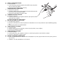
HOW TO REMOVE BATTERIES
● Remove the lid.
● Press the battery toward the negative end and lift it out by its positive
end (as shown in the figure).
● Remove the other battery in the same way.
COME RIMUOVERE LE BATTERIE
● Rimuovere il coperchio.
● Premere la batteria verso il polo negativo ed estrarla dalla parte del
polo positivo (come mostrato in figura).
● Rimuovere l’altra batteria allo stesso modo.
COMMENT ENLEVER LES PILES
● Enlever le couvercle.
● Pousser la pile vers le pôle négatif et enlever le pôle positif (comme
représenté dans la figure).
● Enlever l’autre pile de la même manière.
WIE DIE BATTERIEN ZU ENTFERNEN
● Die Abdeckung entfernen.
● Drucken Sie die Batterie nach dem negativen Pol und entfernen Sie sie vom positiven Pol (wie in Abbildung gezeigt
ist).
● Entfernen Sie ebenso die andere Batterie.
COMO REMOVER LAS PILAS
● Remover la tapa.
● Apretar la pila hacia el polo negativo y remover el polo positivo (como en figura).
● Remover así también la otra pila.
COMO REMOVER AS PILHAS
● Remover a tampa.
● Premir a pilha para o polo negativo e remover a parte do polo positivo (como indicado na figura).
● Remover a outra pilha ao mesmo modo.
¶ø™ ¡∞ ∞º∞πƒ∂™∂Δ∂ Δπ™ ª¶∞Δ∞ƒπ∂™
● ¶È¤ÛÙ ÙËÓ Ì·Ù·Ú›· ÚÔ˜ ÙÔÓ ·ÚÓËÙÈÎfi fiÏÔ Î·È ·Ê·ÈÚ¤ÛÙ ÙËÓ ·fi ÙË ÌÂÚÈ¿ ÙÔ˘ ıÂÙÈÎÔ‡ fiÏÔ˘ (fiˆ˜ Ê·›ÓÂÙ·È
ÛÙËÓ ÂÈÎfiÓ·).
● ∞Ê·ÈÚ¤ÛÙ ÙËÓ ¿ÏÏË Ì·Ù·Ú›· Ì ÙÔÓ ›‰ÈÔ ÙÚfiÔ.
I
EG
F
D
E
P
GR

Do not vent R410Ainto atmosphere: R410A is a fluorinated greenhouse gas, covered by Kyoto
Protocol, with a Global Warming Potential (GWP) = 1975.
Non disperdere R410A nell'atmosfera: R410A è un gas fluorinato a effetto serra, coperto dal
protocollo di Kyoto, con potenziale di riscaldamento globale (GWP) = 1975.
Ne déchargez pas R410A dans l'atmosphère : R410A est un gaz fluoré à effet de serre, couvert
par le protocole de Kyoto, avec un potentiel de chauffage global (GWP) = 1975.
Zerstreuen Sie R410A in Atmosphäre nicht: R410A ist ein fluoriertes Gas, abgedeckt durch
Kyoto Protokoll, mit einem globalen wärmenden Potential (GWP) = 1975.
No expulsar R410A a la atmósfera: el R410A es un gas fluorado de efecto invernadero, cubierto
por el protocolo de Kyoto, con potencial de calentamiento global (GWP) = 1975.
Não exale R410A na atmosfera: R410A é um fluorinated gás, coberto pelo protocolo de Kyoto,
com um global Potencial Aquecendo-se (GWP) = 1975.
ªËÓ ·ÂÚ›ÛÙ R410A ÛÙËÓ ·ÙÌfiÛÊ·ÈÚ·: R410A Â›Ó·È ¤Ó· ÊıÔÚȈ̤ÓÔ ıÂÚÌÔ΋ÈÔ ·¤ÚÈÔ, Ô˘
ηχÙÂÙ·È ·fi ÙÔ ÚˆÙfiÎÔÏÏÔ ÙÔ˘ ∫ÈfiÙÔ, Ì ¤Ó·Ó ÛÊ·ÈÚÈÎfi ¢˘Ó·ÙfiÙËÙ· ı¤ÚÌ·ÓÛ˘ (GWP)
= 1975.
I
EG
F
D
E
P
GR
F-GAS Regulation (EC) No. 842/2006
R.D. 28 Reyrieux BP 131 - 01601 Trévoux CEDEX France
Tél. 04.74.00.92.92 - Fax 04.74.00.42.00
R.C.S. Bourg-en-Bresse B 759 200 728
In order to carry on a constant improvement, our products can be modified without prior notice.
Per garantire un costante miglioramento dei nostri prodotti, ci riserviamo di modificarli senza preavviso.
Par souci d’amélioration constante, nos produits peuvent être modifiés sans préavis.
Unsere Produkte werden laufend verbessert und können Vorankündigung abgeändert Werden.
En el interés de mejoras constantes, nuestros productos pueden modificarse sin aviso prévio.
S.A.C. - Printed in italy
-
 1
1
-
 2
2
-
 3
3
-
 4
4
-
 5
5
-
 6
6
-
 7
7
-
 8
8
-
 9
9
-
 10
10
-
 11
11
-
 12
12
-
 13
13
-
 14
14
-
 15
15
-
 16
16


TECHNIBEL CA8FIA0R5I Istruzioni per l'uso
- Categoria
- Condizionatori d'aria mobili
- Tipo
- Istruzioni per l'uso
in altre lingue
Documenti correlati
Altri documenti
-
LG USNW186K3A0 Manuale del proprietario
-
Panasonic CSME7NKE Istruzioni per l'uso
-
Argoclima Magico 9.2 Istruzioni per l'uso
-
Airwell RC08A Manuale utente
-
Hitachi RAK-25PPA Manuale utente
-
-
-
-
-