Yamaha RX-V350 Manuale del proprietario
- Categoria
- Ricevitori AV
- Tipo
- Manuale del proprietario

RX-V350
G
AV Receiver
Ampli-tuner audio-vidéo
YAMAHA ELECTRONICS CORPORATION, USA 6660 ORANGETHORPE AVE., BUENA PARK, CALIF. 90620, U.S.A.
YAMAHA CANADA MUSIC LTD. 135 MILNER AVE., SCARBOROUGH, ONTARIO M1S 3R1, CANADA
YAMAHA ELECTRONIK EUROPA G.m.b.H. SIEMENSSTR. 22-34, 25462 RELLINGEN BEI HAMBURG, F.R. OF GERMANY
YAMAHA ELECTRONIQUE FRANCE S.A. RUE AMBROISE CROIZAT BP70 CROISSY-BEAUBOURG 77312 MARNE-LA-VALLEE CEDEX02, FRANCE
YAMAHA ELECTRONICS (UK) LTD. YAMAHA HOUSE, 200 RICKMANSWORTH ROAD WATFORD, HERTS WD18 7GQ, ENGLAND
YAMAHA SCANDINAVIA A.B. J A WETTERGRENS GATA 1, BOX 30053, 400 43 VÄSTRA FRÖLUNDA, SWEDEN
YAMAHA MUSIC AUSTRALIA PTY, LTD. 17-33 MARKET ST., SOUTH MELBOURNE, 3205 VIC., AUSTRALIA
Printed in China
WD06070
©2004 All rights reserved.
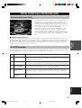
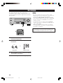
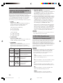
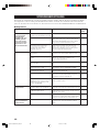
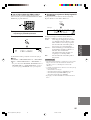
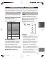
ТЕХНИЧЕСКИЕ ХАРАКТЕРИСТИКИ
РАЗДЕЛ FМ
• Диапазон настройки
[Модели для США и Канады] ................... 87,5 – 107,9 МГц
[Другие модели] .................................... 87,50 – 108,00 МГц
• 50 дБ Чувствительность спокойствия (IHF, 100% mod.)
Моно/Стерео ............... 2,0 мВ (17,3 дБf) /25 мВ (39,2 дБf)
• Селективность (400 кГц) ............................................ 70 дБ
• Соотношение сигнал/шум (IHF)
Моно/Стерео ................................................... 76 дБ/70 дБ
• Нелинейное искажение (1 кГц)
Моно/Стерео ..................................................... 0,2%/0,3%
• Стереофоническое разделение (1 кГц) .................... 42 дБ
• Частотная характеристика ........ 20 Гц – 15 кГц +0,5, –2 дБ
РАЗДЕЛ AM
• Диапазон настройки ..................... 530/531 – 1710/1611 кГц
• Используемая чувствительность ......................... 300 мВ/м
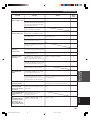
ОБЩИЙ РАЗДЕЛ
• Электропитание
[Модели для США и Канады]
........................................ 120 В переменного тока/60 Гц
[Модель для Австралии] .. 240 В переменного тока/50 Гц
[Модели для Соединенного Королевства
Великобритании и Северной Ирландии и Европы]
........................................ 230 В переменного тока/50 Гц
[Модель для Кореи] ......... 220 В переменного тока/60 Гц
[Модель для Китая] ......... 220 В переменного тока/50 Гц
[Модель для Азии и общая модель]
.......... 110-120 В/220-240 В переменного тока, 50/60 Гц
• Электропотребление
[Модели для США и Канады] ................. 240 Ватт/320 ВА
[Другие модели] .................................................... 240 Ватт
• Электропотребление в режиме ожидания
[Модели для США и Канады] ............................... 0,5 Ватт
[Другие модели] ..................................................... 0,7 Ватт
•Габариты (Ш x В x Г) ............................... 435 x 151 x 315 мм
• Вес ................................................................................... 9 кг
* Технические характеристики могут быть изменены без
уведомления.
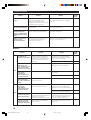
АУДИОРАЗДЕЛ
• Минимальное электрическое напряжение RMS для
фронтального, центрального канала и каналов
окружающего звучания
1 кГц, 0.1% THD (общее нелинейное искажение), 6 Ом
[Модели для США и Канады] .............................. 100 Ватт
[Другие модели] ...................................................... 90 Ватт
1 кГц, 0.7% THD (общее нелинейное искажение), 6 Ом
[Модели для США и Канады] .............................. 103 Ватт
[Другие модели] ...................................................... 93 Baтт
• Стандартное электрическое напряжение DIN
[Модель для Европы]
1 кГц, 0.7% THD (общее нелинейное искажение),
4 Ом .................................................................... 105 Ватт
• Максимальное напряжение
[Основная модель и модели для Китая и Кореи]
1 кГц, 10% THD (общее нелинейное искажение),
6 Ом .................................................................... 110 Ватт
• Динамическое напряжение (IHF, 6/4/2 Ом)
[Модели для США и Канады] ................. 110/140/170 Ватт
[Другие модели] ...................................... 105/135/165 Ватт
• Частотная характеристика
CD, т.д. для фронтальных левого и правого
каналов ........................................ 10 Гц – 100 кГц, –3 дБ
• Общее нелинейное искажение
1 кГц, 50 Ватт, 6 Ом, фронтальные левый и
правый ................................................................... 0,06%
• Соотношение сигнал/шум (Сеть IHF-A)
CD (250 мВ, укороченный) для фронтальных левого и
правого каналов, эффекты оключены ........... h100 дБ
• Остаточный шум (Сеть IHF-A)
Фронтальный левый и правый ......... 150 мВ или меньше
• Разделение каналов (1 кГц/10 кГц)
CD, другое (5,1 кОм, прерванный) для фронтальных
левого и правого каналов ................... h60 дБ/h45 дБ
• Тональный контроль (фронтальные левый и правый)
BASS Добавочное напряжение/
Разделение ............................................... ±10 дБ/100 Гц
TREBLE Добавочное напряжение/
Разделение ............................................... ±10 дБ/20 кГц
• Выходная мощность на колонки ................. 400 мВ/470 Ом
• Чувствительность приема
CD, т.д. ........................................................ 200 мВ/47 кОм
6CH INPUT .................................................. 200 мВ/47 кОм
• Выходная мощность
OUT (REC) ................................................. 200 мВ/1.2 кОм
OUTPUT SUBWOOFER ................................... 4 В/1.2 кОм
ВИДЕОРАЗДЕЛ
• Тип видеосигнала ......................................... NTSC или PAL
• Уровень композитного видеосигнала ............ 1 Vp-p/75 Ом
• Соотношение сигнал/шум ....................................... h50 дБ
• Частотный ответ (MONITOR OUT)
......................................................... 5 Гц – 10 МГц, –3 дБ
OWNER’S MANUAL
MODE D’EMPLOI
BEDIENUNGSANLEITUNG
BRUKSANVISNING
GEBRUIKSAANWIJZING
ИНСТРУКЦИЯ ПО ЭКСПЛУАТАЦИИ
RX-V350
RX-V350_WD06070_cover.p65 2/17/04, 11:35 PM1

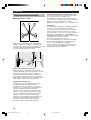
1 To assure the finest performance, please read this
manual carefully. Keep it in a safe place for future
reference.
2 Install this sound system in a well ventilated, cool,
dry, clean place — away from direct sunlight, heat
sources, vibration, dust, moisture, and/or cold.
Allow ventilation space of at least 30 cm on the top,
20 cm on the left and right, and 20 cm on the back
of this unit.
3 Locate this unit away from other electrical
appliances, motors, or transformers to avoid
humming sounds.
4
Do not expose this unit to sudden temperature
changes from cold to hot, and do not locate this unit
in a environment with high humidity (i.e. a room with
a humidifier) to prevent condensation inside this unit,
which may cause an electrical shock, fire, damage to
this unit, and/or personal injury.
5 Avoid installing this unit where foreign object may
fall onto this unit and/or this unit may be exposed
to liquid dripping or splashing. On the top of this
unit, do not place:
– Other components, as they may cause damage
and/or discoloration on the surface of this unit.
–
Burning objects (i.e. candles), as they may cause
fire, damage to this unit, and/or personal injury.
– Containers with liquid in them, as they may fall
and liquid may cause electrical shock to the
user and/or damage to this unit.
6 Do not cover this unit with a newspaper, tablecloth,
curtain, etc. in order not to obstruct heat radiation.
If the temperature inside this unit rises, it may
cause fire, damage to this unit, and/or personal
injury.
7 Do not plug in this unit to a wall outlet until all
connections are complete.
8 Do not operate this unit upside-down. It may
overheat, possibly causing damage.
9 Do not use force on switches, knobs and/or cords.
10 When disconnecting the power cord from the wall
outlet, grasp the plug; do not pull the cord.
11 Do not clean this unit with chemical solvents; this
might damage the finish. Use a clean, dry cloth.
12 Only voltage specified on this unit must be used.
Using this unit with a higher voltage than specified
is dangerous and may cause fire, damage to this
unit, and/or personal injury. YAMAHA will not be
held responsible for any damage resulting from use
of this unit with a voltage other than specified.
13
To prevent damage by lightning, disconnect the power
cord from the wall outlet during an electrical storm.
14 Do not attempt to modify or fix this unit. Contact
qualified YAMAHA service personnel when any
service is needed. The cabinet should never be
opened for any reasons.
15 When not planning to use this unit for long periods
of time (i.e. vacation), disconnect the AC power
plug from the wall outlet.
CAUTION: READ THIS BEFORE OPERATING YOUR UNIT.
16 Be sure to read the “TROUBLESHOOTING” section
on common operating errors before concluding that
this unit is faulty.
17 Before moving this unit, press STANDBY/ON to set
this unit in standby mode, and disconnect the AC
power plug from the wall outlet.
18
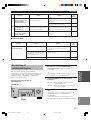
VOLTAGE SELECTOR (Asia and Greneral models only)
The VOLTAGE SELECTOR on the rear panel of this
unit must be set for your local main voltage
BEFORE plugging into the AC main supply.
Voltages are 110V-120V, 220V-240V AC, 50/60 Hz.
This unit is not disconnected from the AC power
source as long as it is connected to the wall outlet,
even if this unit itself is turned off. This state is called
standby mode. In this state, this unit is designed to
consume a very small quantity of power.
WARNING
TO REDUCE THE RISK OF FIRE OR ELECTRIC
SHOCK, DO NOT EXPOSE THIS UNIT TO RAIN
OR MOISTURE.
■ For U.K. customers
If the socket outlets in the home are not suitable for the
plug supplied with this appliance, it should be cut off and
an appropriate 3 pin plug fitted. For details, refer to the
instructions described below.
Note
• The plug severed from the mains lead must be destroyed, as a
plug with bared flexible cord is hazardous if engaged in a live
socket outlet.
■ Special Instructions for U.K. Model
IMPORTANT
THE WIRES IN MAINS LEAD ARE COLOURED
IN ACCORDANCE WITH THE FOLLOWING
CODE:
Blue: NEUTRAL
Brown: LIVE
As the colours of the wires in the mains lead of this
apparatus may not correspond with the coloured
markings identifying the terminals in your plug,
proceed as follows:
The wire which is coloured BLUE must be connected
to the terminal which is marked with the letter N or
coloured BLACK. The wire which is coloured
BROWN must be connected to the terminal which is
marked with the letter L or coloured RED.
Making sure that neither core is connected to the earth
terminal of the three pin plug.
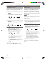
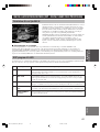
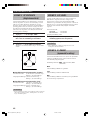
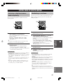
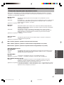
СПРАВОЧНИК
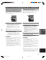
■ Канал LFE 0.1
Данный канал предназначен для
воспроизведения низкочастотных сигналов.
Данный канал обладает частотным диапазоном
20 Гц – 120 Гц. Данный канал считается как 0.1,
так как он позволяет только усилить
низкочастотный диапазон, по сравнению с
полнодиапазонным воспроизведением других
5 каналов в 5.1-канальных системах Dolby Digital
или DTS.
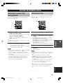
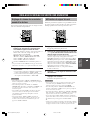
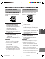
■ Matrix 6.1
Данный аппарат оснащен декодером Matrix 6.1
для многоканальных программ в формате
Dolby Digital и DTS, и позволяет производеть
6.1-канальное воспроизведение путем
добавления дополнительного тылового канала
окружающего звучания к существующему
5.1-канальному формату. (Тыловой канал
окружающего звучания воспроизводится от
левой и правой колонок окружающего звучания,
и выводится от виртуальной тыловой колонки
окружающего звучания.) Используя данный
дополнительный канал, вы можете насладиться
более динамичным и реалистичным движущимся
звучанием, особенно во время сцен с
эффектами “пролета” или “облета”.
■ PCM (Линейный PCM)
Линейный PCM – это формат сигнала,
позволяющий преобразовывать аналоговые
аудиосигналы в цифровые формат, и записывать
и передавать их без дополнительного сжатия.
Данный метод используется для аудиозаписи на
CD-дисках и DVD-дисках. Система PCM
использует технологию производства отбора
размера аналогового сигнала на очень короткую
единицу времени. Известный как “модуляция
импульсного кода”, аналоговый сигнал
кодируется в виде импульсов и затем
модулируется для записи.
■ Частота стробирования и количество
квантованных битов
При преобразовании аналогового аудиосигнала в
цифровой формат, частотой стробирования
называют количество раз стробирования
сигнала в секунду, в то время как количество
квантованных битов определяется как уровень
чистоты при преобразовании уровней звука в
цифровое значение.
Диапазон амплитудно-импульсной модуляции
для воспроизводения зависит от частоты
амплитудно-импульсной модуляции, в то время
как динамический диапазон, представляющий
собой разницу уровней звучания, определяется
количеством квантованных битов. В принципе,
чем выше частота амплитудно-импульсной
модуляции, тем шире диапазон частот для
воспроизведения, и чем больше количество
квантованных битов, тем чище воспроизведение
уровней звучания.
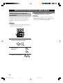
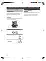
■ SILENT CINEMA
YAMAHA разработала алгоритм звуковых
эффектов DSP для естественного,
реалистичного воспроизведения для наушников.
Параметры для наушников установлены в
каждом звуковом поле, позволяя аккуратно
воспроизводить все программы звуковых полей
для прослушивания с использованием
наушников.
■ Virtual CINEMA DSP
YAMAHA разработала алгоритм виртуального
CINEMA DSP, использующий виртуальные
колонки окружающего звучания, и позволяющий
прослушивать эффекты окружающего звучания
звукового поля DSP даже без использования
колонок окружающего звучания.
Вы можете даже воспроизводить виртуальные
эффекты CINEMA DSP даже с использованием
минимальной 2-колоночной системы, которая не
включает центральную колонку.
53
Русский
ДОПОЛНИТЕЛЬНАЯ
ИНФОРМАЦИЯ
RX-V350_WD06070_cover.p65 2/17/04, 11:35 PM2

1
English
INTRODUCTION
PREPARATION
BASIC
OPERATION
ADVANCED
OPERATION
ADDITIONAL
INFORMATION
CONTENTS
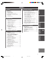
ADDITIONAL INFORMATION
EDITING SOUND FIELD PARAMETERS ..... 46
Changing parameter settings ................................... 46
Sound field parameter descriptions ......................... 47
TROUBLESHOOTING ...................................... 48
Resetting the factory presets ................................... 51
GLOSSARY .......................................................... 52
SPECIFICATIONS .............................................. 54
INTRODUCTION
CONTENTS ............................................................ 1
FEATURES ............................................................. 2
GETTING STARTED ............................................ 3
Supplied accessories .................................................. 3
Installing batteries in the remote control ................... 3
CONTROLS AND FUNCTIONS ......................... 4
Front panel ................................................................ 4
Remote control .......................................................... 6
Front panel display .................................................... 8
ADVANCED OPERATION
SET MENU ........................................................... 39
Set menu list ............................................................ 39
Adjusting the items on the set menu ....................... 39
SOUND 1 SPEAKER SET (speaker mode settings)
............................................................................. 40
SOUND 2 SP DISTANCE (speaker distance) ........ 42
SOUND 3 LFE LEVEL .......................................... 42
SOUND 4 D. RANGE (dynamic range) ................. 42
SOUND 5 CENTER GEQ
(center graphic equalizer) ................................... 43
SOUND 6 HP TONE CTRL
(headphone tone control) .................................... 43
INPUT 1 I/O ASSIGN (input/output assignment) .. 43
INPUT 2 INPUT MODE (initial input mode) ........ 43
OPTION 1 DISPLAY SET ...................................... 44
OPTION 2 MEM. GUARD (memory guard) ......... 44
OPTION 3 AUDIO MUTE ..................................... 44
SETTING THE SPEAKER LEVELS ................ 45
Adjusting the speaker levels during playback ......... 45
Using the test tone ................................................... 45
BASIC OPERATION
PLAYBACK .......................................................... 21
Input modes and indications .................................... 23
Selecting a sound field program .............................. 24
DIGITAL SOUND FIELD PROCESSING (DSP)
............................................................................ 27
Understanding sound fields ..................................... 27
HiFi DSP programs ................................................. 27
CINEMA DSP ...................................................... 28
Sound design of CINEMA DSP .............................. 28
CINEMA DSP Programs ........................................ 28
Sound field effects ................................................... 30
TUNING ................................................................ 31
Presetting stations .................................................... 32
Selecting preset stations .......................................... 34
RECEIVING RDS STATIONS ........................... 35
Description of RDS data ......................................... 35
Changing the RDS mode ......................................... 35
PTY SEEK function ................................................ 36
EON function .......................................................... 36
SLEEP TIMER ..................................................... 37
RECORDING ....................................................... 38
PREPARATION
CONNECTIONS .................................................... 9
Before connecting components ................................. 9
Connecting video components ................................ 10
Connecting audio components ................................ 11
Connecting the antennas ......................................... 12
Connecting an external decoder .............................. 13
Connecting the speakers .......................................... 14
Connecting the power supply cords ........................ 17
Turning on the power .............................................. 17
BASIC SYSTEM SETTINGS ............................. 18
Using the basic menu .............................................. 18
Setting the unit to match your speaker system ........ 20
2 SP LEVEL (Setting speaker output levels) .......... 20
RX-V350_WD06070_EN.p65 1/19/04, 6:43 PM1

2
Manufactured under license from Dolby Laboratories.
“Dolby”, “Pro Logic”, and the double-D symbol are
trademarks of Dolby Laboratories.
“SILENT CINEMA” is a trademark of YAMAHA
CORPORATION.
FEATURES
Sound field features
◆ Dolby Pro Logic/Dolby Pro Logic II decoder
◆ Dolby Digital/Dolby Digital + Matrix 6.1 Decoder
◆ DTS/DTS + Matrix 6.1 Decoder
◆ CINEMA DSP: Combination of YAMAHA DSP
technology and Dolby Pro Logic, Dolby Digital or
DTS
◆ Virtual CINEMA DSP
◆ SILENT CINEMA ™
Sophisticated AM/FM Tuner
◆ 40-Station random access preset tuning
◆ Automatic preset tuning
◆ Preset station shifting capability (Preset editing)
Other features
◆ 96 kHz/24-bit D/A converter
◆ Set menu for optimizing this unit for your Audio/
Video system
◆ Test tone generator for easier speaker balance
adjustment
◆ 6-channel external decoder input
◆ Optical and coaxial digital audio signal jacks
◆ Sleep timer
“DTS” and “DTS Digital Surround” are registered
trademarks of Digital Theater Systems, Inc.
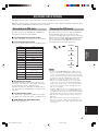
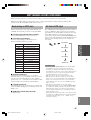
Built-in 5-channel power amplifier
◆ Minimum RMS output power
(0.1% THD, 1 kHz, 6Ω)
[U.S.A. and Canada models]
Front: 100 W + 100 W
Center: 100 W
Surround: 100 W + 100 W
[Other models]
Front: 90 W + 90 W
Center: 90 W
Surround: 90 W + 90 W
■ About this manual
• y indicates a tip for your operation.
• Some operations can be performed by using either the buttons on the main unit or on the remote control. In cases
when the button names differ between the main unit and the remote control, the button name on the remote control is
given in parentheses.
• This manual is printed prior to production. Design and specifications are subject to change in part for the reason of
the improvement in operativity ability, and others. In this case, the product has priority.
RX-V350_WD06070_EN.p65 1/19/04, 6:43 PM2

3
English
INTRODUCTION
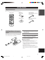
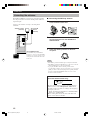
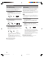
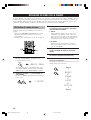
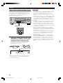
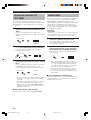
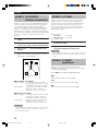
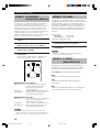
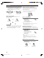
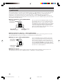
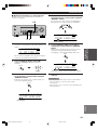
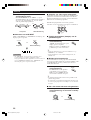
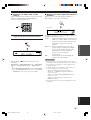
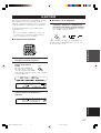
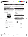
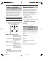
Installing batteries in the remote
control
Insert the batteries in the correct direction by aligning the
+ and – marks on the batteries with the polarity markings
(+ and –) inside the battery compartment.
1 Press the tab of the battery compartment
cover and pull it in the direction of the arrow
to open the cover.
2 Remove the cover.
3 Insert the two batteries supplied (AA, R06,
UM-3) according to the polarity markings on
the inside of the battery compartment.
4 Put the cover back into place.
■ Notes on batteries
• Change all of the batteries if you notice a decrease in
the operating range of the remote control.
• Do not use old batteries together with new ones.
• Do not use different types of batteries (such as alkaline
and manganese batteries) together. Read the packaging
carefully as these different types of batteries may have
the same shape and color.
• If the batteries have leaked, dispose of them
immediately. Avoid touching the leaked material or
letting it come into contact with clothing, etc. Clean the
battery compartment thoroughly before installing new
batteries.
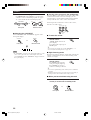
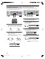
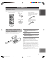
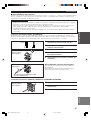
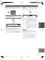
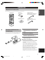
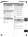
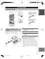
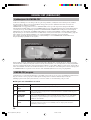
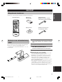
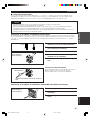
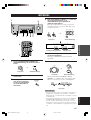
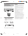
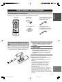
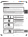
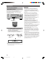
AM loop antenna
(Europe, U.K., Australia and
Korea models)
Indoor FM antenna
(U.S.A., Canada, China, Asia and
General models)
Batteries (2)
(AA, R06, UM-3)
Remote control
GETTING STARTED
Supplied accessories
Please check that you received all of the following parts.
TEST
PROG PROG
STEREO
LEVEL
SET MENU
TUNER
CD MD/CD-R V-AUX 6CH IN
/DTS 6.1/5.1 NIGHT SLEEP
DVD D-TV/CBL VCR POWER
PRESET
A/B/C/D/E
MUTE
VOLUME
VOLUME
1
2
4
3
RX-V350_WD06070_EN.p65 1/19/04, 6:43 PM3

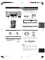
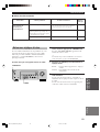
4
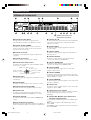
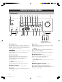
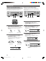
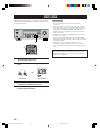
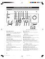
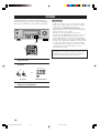
CONTROLS AND FUNCTIONS
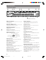
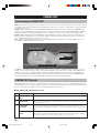
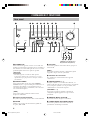
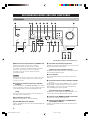
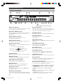
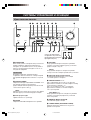
Front panel
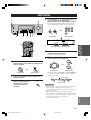
1 STANDBY/ON
Turns on this unit or sets it to the standby mode. When
you turn on this unit, you will hear a click and there will
be a 4 to 5-second delay before this unit can reproduce
sound.
Note
In standby mode, this unit consumes a small amount of
power in order to receive infrared-signals from the remote
control.
2 PRESET/TUNING
Switches the function of PRESET/TUNING l / h
between selecting a preset station number and tuning (the
colon (:) turns on or off).
(EDIT)
This button is also used to exchange the assignment of
two preset stations with each other.
3 Remote control sensor
Receives signals from the remote control.
4 FM/AM
Switches the reception band between FM and AM.
5 A/B/C/D/E
Selects preset station groups A to E when the unit is in
tuner mode.
(NEXT)
Selects the set menu mode when the unit is not in tuner
mode.
6 Front panel display
Shows information about the operational status of the
unit.
7 PRESET/TUNING l / h
Select preset station numbers 1 to 8 when a colon (:) is
displayed in the front panel display.
Select the tuning frequency when a colon (:) is not
displayed when the unit is in tuner mode.
(SET MENU –/+)
Adjust settings on the set menu when the unit is not in
tuner mode.
8 MEMORY (MAN’L/AUTO FM)
Stores a station in the memory.
9 TUNING MODE (AUTO/MAN’L MONO)
Switches the tuning mode between automatic and manual.
(U.K. and Europe models only)
PRESET/TUNING
EDIT
FM/AM A/B/C/D/E
NEXT
PRESET/TUNING
INPUT MODE 6CH INPUT
SET MENU
MEMORY
MAN'L/AUTO FM
TUNING MODE
AUTO/MAN'L MONO
RDS MODE/FREQ EON
PTY SEEK
MODE START
VOLUME
STEREO PROGRAM INPUT
EFFECT
CONTROL
BASS/TREBLE
STANDBY
/ON
PHONES
SILENT CINEMA
SPEAKERS
A/B/OFF
32 4 51 986 0
r
p a ds
q w e uyt oi
RDS MODE/FREQ EON
PTY SEEK
MODE START
7
RX-V350_WD06070_EN.p65 1/19/04, 6:43 PM4

5
English
INTRODUCTION
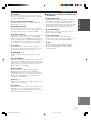
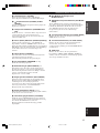
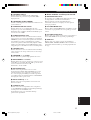
0 VOLUME
Controls the output level of all audio channels.
This does not affect the OUT (REC) level.
q
PHONES (SILENT CINEMA)
Allows you to enjoy DSP effects when listening with
headphones.
w SPEAKERS A/B/OFF
Selects the set of front speakers connected to the A or B
terminals. To turn off the speakers, press the button
repeatedly and select OFF.
e STEREO (EFFECT)
Switches between normal stereo and DSP effect
reproduction. When you select STEREO, the unit mixes
down all Dolby Digital and DTS signals (except the LFE
channel) as well as those 2-channel signals without effect
sounds, to the front left and right speakers.
r CONTROL
Switches between Bass (low-frequency response) control
mode and Treble (high-frequency response) control mode.
t PROGRAM l / h
Use to select sound field programs.
y BASS/TREBLE –/+
Increase or decrease low/high-frequency response when
the unit is in Bass/Treble control mode. The sound
changes 2dB each time you press one of these buttons.
Control range: –10 to +10dB.
u INPUT MODE
Sets the priority for the types of input signals (AUTO,
DTS, ANALOG) received when one component is
connected to two types of input jacks. You cannot set
priority for an audio sources if you have selected 6CH
INPUT as the input source.
i INPUT l / h
Selects the input source you want to listen to or watch.
o 6CH INPUT
Selects the audio source connected to the 6CH INPUT
jacks. This selection takes priority over sources selected
with INPUT (or the input selector buttons on the remote
control).
CONTROLS AND FUNCTIONS
■ U.K. and Europe models only
p RDS MODE/FREQ
Press this button when the unit is receiving an RDS
station, to cycle the display mode among PS mode, PTY
mode, RT mode, CT mode (if the station offers those
RDS data service) and/or frequency display mode in turn.
a PTY SEEK MODE
Press this button to set the unit in the PTY SEEK mode.
s PTY SEEK START
Press this button to begin searching for a station after the
desired program type has been selected in the PTY SEEK
mode.
d EON
Press this button to select a radio program type (NEWS,
INFO, AFFAIRS, SPORT) to tune in automatically.
RX-V350_WD06070_EN.p65 1/19/04, 6:43 PM5

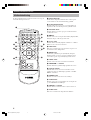
6
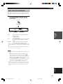
CONTROLS AND FUNCTIONS
TEST
PROG PROG
STEREO
LEVEL
SET MENU
TUNER
CD MD/CD-R V-AUX 6CH IN
/DTS 6.1/5.1 NIGHT SLEEP
DVD D-TV/CBL VCR
PRESET
A/B/C/D/E
MUTE
VOLUME
VOLUME
POWER
2
8
1
0
3
5
9
7
4
6
r
y
e
q
w
t
u
i
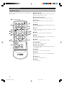
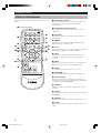
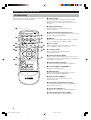
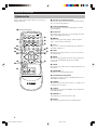
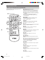
Remote control
1 Infrared emitter
Outputs infrared control signals. Aim this emitter at the
unit when using the remote control.
2 Input selector buttons
Select the input source and change the control area.
3 A/B/C/D/E
Selects preset station groups A to E when the unit is in
tuner mode.
4 q/DTS
Selects the built-in Dolby Digital, DTS, Dolby Pro Logic
or Pro Logic II decoder.
5 6.1/5.1
Switches on or off the Dolby Digital + Matrix 6.1 or DTS
+ Matrix 6.1 decoder.
6 TEST
Outputs the test tone to adjust the speaker levels.
7 MUTE
Mutes the sound. Press again to restore the audio output
to the previous volume level.
8 LEVEL
Selects the effect speaker channel to adjust.
9 PROGRAM –/+
Use to select sound field programs.
0 Multi control section
Use to select and adjust sound field program parameters
or SET MENU items.
q POWER
Turns the unit on, or sets it in standby mode.
w 6CH IN
Selects the audio source connected to the 6CH INPUT
jacks.
e PRESET –/+
Select preset station numbers 1 to 8.
r SLEEP
Sets the sleep timer.
This section describes the function of each control on the
remote control.
RX-V350_WD06070_EN.p65 1/19/04, 6:43 PM6

7
English
INTRODUCTION
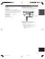
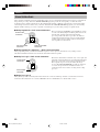
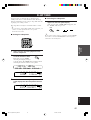
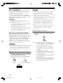
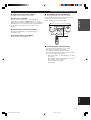
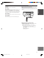
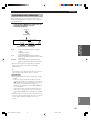
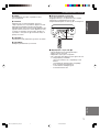
Approximately 6 m (20 feet)
■ Using the remote control
The remote control transmits a directional infrared beam.
Be sure to aim the remote control directly at the remote
control sensor on the main unit during operation.
■ Handling the remote control
• Do not spill water or other liquids on the remote
control.
• Do not drop the remote control.
• Do not leave or store the remote control in the
following types of conditions:
– high humidity such as near a bath
– high temperature such as near a heater or stove
– extremely low temperature
– dusty places
PRESET/TUNING
EDIT
FM/AM A/B/C/D/E
NEXT
PRESET/TUNING
INPUT MODE 6CH INPUT
SET MENU
MEMORY
MAN'L/AUTO FM
TUNING MODE
AUTO/MAN'L MONO
RDS MODE/FREQ EON
PTY SEEK
MODE START
VOLUME
STEREO PROGRAM INPUT
EFFECT
CONTROL
BASS/TREBLE
STANDBY
/ON
PHONES
SILENT CINEMA
SPEAKERS
A/B/OFF
30° 30°
CONTROLS AND FUNCTIONS
t NIGHT
Sets the unit in night listening mode.
y STEREO
Switches between normal stereo and DSP effect
reproduction. When you select STEREO the unit mixes
down all Dolby Digital and DTS signals (except the LFE
channel) as well as those 2-channel signals without effect
sounds, to the front left and right speakers.
u VOLUME +/–
Increases or decreases the volume level.
i SET MENU
Selects the set menu mode.
RX-V350_WD06070_EN.p65 1/19/04, 6:43 PM7

8
V-AUXVCR
DTV/CBL
DVD
MD/CD-R
TUNER CD
MATRIX
DIGITAL
PCM
PL
PL
SILENT CINEMA
DSP
HiFi
NIGHT
VIRTUAL
A B
SP
STEREO
VOLUME
MUTE
MEMORY
TUNED
L C R
SL
LFE
SB SR
~~~~~~~~~~~~~~
dB
dB
ft
CTRTPTYPS
HOLD AUTOPTY
EON
SLEEP
13
45
8
7
62
90qw y urt ieop
s
a
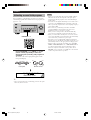
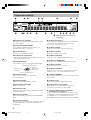
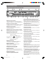
1 Decoder indicators
When any of this unit’s decoders function, the respective
indicator lights up.
2 SILENT CINEMA indicator
Lights up when headphones are connected and a sound
field program is selected (see page 26).
3 Headphones indicator
Lights up when headphones are connected to the
headphone jack.
4 Input source indicator
Highlights the current input source with a cursor.
5 Sound field indicator
Light to indicate the active DSP sound fields.
6 AUTO indicator
Shows that this unit is in the automatic tuning mode.
7 MUTE indicator
Flashes while the MUTE function is on.
8 VOLUME level indicator
Indicates the volume level.
9 PCM indicator
Lights up when this unit is reproducing PCM (pulse code
modulation) digital audio signals.
0 VIRTUAL indicator
Lights up when using Virtual CINEMA DSP.
q Multi-information display
Shows the current sound field program name and other
information when adjusting or changing settings.
w SP A B indicator
Lights up to indicate which set of front speakers is
selected. Both indicators light up when both sets of
speakers are selected.
e NIGHT indicator
Lights up when the unit is set to night listening mode.
r SLEEP indicator
Lights up while the sleep timer is on.
t HiFi DSP indicator
Lights up when you select a HiFi DSP sound field
program.
y CINEMA DSP indicator
Lights up when you select a CINEMA DSP sound field
program.
u TUNED indicator
Lights up when this unit is tuned to a radio station.
i STEREO indicator
Lights up when the unit is receiving a strong signal from
a FM stereo broadcast while the “AUTO” indicator is lit.
o MEMORY indicator
Flashes to show a station can be stored.
p LFE indicator
Lights up when the input signal contains an LFE signal.
a Input channel indicator
The indicators for the appropriate sound channels light up
when a digital signal from a source is played back.
s RDS indicator (U.K. and Europe models only)
The name(s) of the RDS data offered by the currently
received RDS station light(s) up.
EON lights up when an RDS station that offers the EON
data service is being received.
PTY HOLD lights up while searching for stations in the
PTY SEEK mode.
Front panel display
(U.K. and Europe models only)
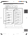
CONTROLS AND FUNCTIONS
Presence DSP sound field
Listening position
Right surround
DSP sound field
Surround back DSP sound field
Left surround
DSP sound field
RX-V350_WD06070_EN.p65 1/19/04, 6:43 PM8

9
English
PREPARATION
DIGITAL
INPUT
6CH INPUT AUDIO VIDEO TUNER SPEAKERS
AUDIO OUTPUT
L
DVD
R
LR
FRONT
SURROUND
SUB
WOOFER
CENTER
CD
DTV
/CBL
COAXIAL
OPTICAL
CD
IN
(PLAY)
MD
/CD-R
OUT
(REC)
DTV
/CBL
AM
ANT
FM
ANT
GND
75
Ω
UNBAL.
V-AUX
IN
VCR
OUT
SUB
WOOFER
MONITOR
OUT
DVD
3
2
1
L
FRONT
FRONT A OR B : 6
Ω
MIN. /SPEAKER CENTER : 6
Ω
MIN. /SPEAKER
SURROUND : 6
Ω
MIN. /SPEAKER
A
B
R
L
SURROUND
R
L
FRONT
CENTER
R
CLASS 2 WIRING
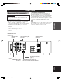
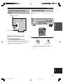
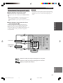
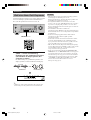
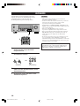
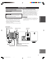
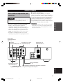
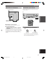
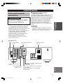
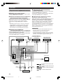
CONNECTIONS
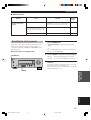
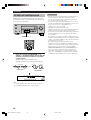
Before connecting components
CAUTION
Do not connect this unit or other components to the
mains power until all connections between the
components have been completed.
• Be sure to connect the left channel (L), right channel
(R), “+” (red) and “–” (black) properly. Some
components require different connection methods and
have different jack names. Refer to the operation
instructions for each component you wish to connect to
this unit.
• After you have completed all connections, check them
again to make sure they are correct.
• The jack names correspond to the names on the input
selector.
■ Connecting to digital jacks
This unit has digital jacks for direct transmission of
digital signals through either a coaxial or fiber optic
cable. You can use the digital jacks to input PCM, Dolby
Digital and DTS bitstreams. Use digital connections if
you wish to enjoy the multi-channel sound track of DVD
material, etc. with DSP effects. Both digital input jacks
are acceptable for 96 kHz sampling digital signals.
Note
• The OPTICAL jack on this unit conform to the EIA standard.
If you use a fiber optic cable that does not conform to EIA
standard, this unit may not function properly.
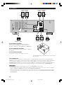
Audio component jacks
(page 11)
DIGITAL INPUT jacks
(pages 9 – 11)
Antenna input terminals
(page 12)
Speaker terminals
(page 16)
Video component jacks
(page 10)
6CH INPUT jacks
(page 13)
SUBWOOFER OUTPUT
jack (page 16)
This jack is reserved for factory use.
Do not connect any equipment to this jack.
RX-V350_WD06070_EN.p65 1/19/04, 6:43 PM9

10
DIGITAL
INPUT
6CH INPUT TUNER
AUDIO OUTPUT
AUDIO VIDEO
L
DVD
R
LR
FRONT
SURROUND
SUB
WOOFER
CENTER
CD
DTV
/CBL
COAXIAL
OPTICAL
CD
IN
(PLAY)
MD
/CD-R
OUT
(REC)
DTV
/CBL
AM
ANT
FM
ANT
GND
75
Ω
UNBAL.
V-AUX
IN
VCR
OUT
SUB
WOOFER
MONITOR
OUT
DVD
3
2
1
VIDEO
INPUT
AUDIO
OUTPUT
LR
AUDIO
INPUT
LR
O
OPTICAL
OUTPUT
VIDEO
OUTPUT
AUDIO
OUTPUT
L
V
R
V V
AUDIO
OUTPUT
L R
VIDEO
OUTPUT
V
O
OPTICAL
OUTPUT
AUDIO
OUTPUT
L R
VIDEO
OUTPUT
V
V
VIDEO
INPUT
VIDEO
OUTPUT
O
L
R
V
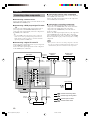
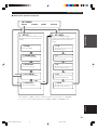
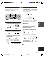
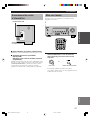
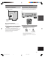
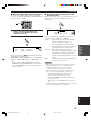
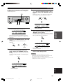
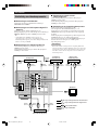
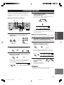
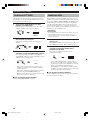
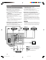
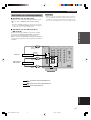
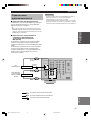
Connecting video components
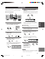
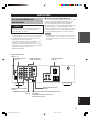
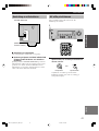
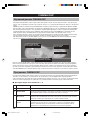
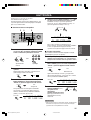
■ Connecting a video monitor
Connect the video input jack on your video monitor to the
MONITOR OUT VIDEO jack.
■ Connecting a DVD player/digital TV/cable
TV
Connect the optical digital audio signal output jack on
your component to the DIGITAL INPUT jack and
connect the video signal output jack on the component to
the VIDEO jack on this unit.
y
• Use the AUDIO jacks on this unit for a video component
which does not have optical digital output jack. However,
multi-channel reproduction cannot be obtained with audio
signals input from the AUDIO jacks.
■ Connecting a digital TV/cable TV
Connect the video signal output jack on your component
to the VIDEO jack on this unit.
Connect the audio signal output jacks on the component
to the AUDIO jacks on this unit.
■ Connecting another video component
Connect the video signal output jack on your component
to the VIDEO jack on this unit.
Connect the audio signal output jacks on the component
to the AUDIO jacks on this unit.
■ Connecting a recording component
Connect the audio signal input jacks on your video
component to the AUDIO OUT jacks on this unit. Then
connect the video signal input jack on the video
component to the VIDEO OUT jack on this unit for
picture recording.
Connect the audio signal output jacks on your component
to the AUDIO IN jacks on this unit. Then connect the
video signal output jack on the component to the VIDEO
IN jack on this unit to play a source from your recording
component.
Note
• Once you have connected a recording component to this unit,
keep its power turned on while using this unit. If the power is
off, this unit may distort the sound from other components.
indicates right analog cables
indicates left analog cables
Video monitor
VCR
DVD player
TV/digital TV/
cable TV
CONNECTIONS
Another video
component
indicates optical cables
indicates video cables
RX-V350_WD06070_EN.p65 1/19/04, 6:43 PM10

11
English
PREPARATION
6CH INPUT AUDIO VIDEO TUNER
OUTPUT
DIGITAL
INPUT
AUDIO
L
DVD
R
LR
FRONT
SURROUND
SUB
WOOFER
CENTER
CD
DTV
/CBL
COAXIAL
OPTICAL
CD
IN
(PLAY)
MD
/CD-R
OUT
(REC)
DTV
/CBL
AM
ANT
FM
ANT
GND
75
Ω
UNBAL.
V-AUX
IN
VCR
OUT
SUB
WOOFER
MONITOR
OUT
DVD
3
2
1
C
L
R
AUDIO
INPUT
L
R
AUDIO
OUTPUT
L
R
COAXIAL
OUTPUT
C
AUDIO
OUTPUT
L
R
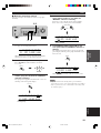
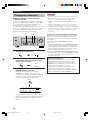
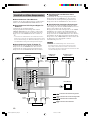
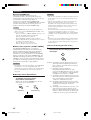
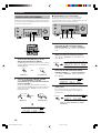
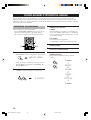
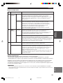
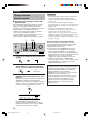
Connecting audio components
■ Connecting a CD player
Connect the coaxial digital output jack on your CD player
to the DIGITAL INPUT CD jack on this unit.
y
• Use the AUDIO jacks on this unit to connect to a CD player
that does not have a COAXIAL DIGITAL OUTPUT jack, or
to record from CD players.
■ Connecting a CD recorder or MD
recorder
Connect the input jacks on your CD recorder or MD
recorder to the MD/CD-R OUT (REC) jacks.
Connect the output jacks on your CD recorder or MD
recorder to the MD/CD-R IN (PLAY) jacks to play a
source from your recording component.
indicates right analog cables
indicates left analog cables
CD player
indicates coaxial cables
CD recorder or
MD recorder
CONNECTIONS
Note
• Once you have connected a recording component to this unit,
keep its power turned on while using this unit. If the power is
off, this unit may distort the sound from other components.
RX-V350_WD06070_EN.p65 1/19/04, 6:43 PM11

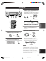
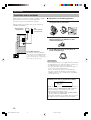
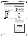
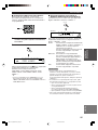
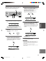
12
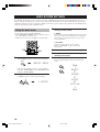
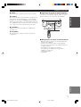
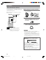
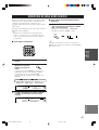
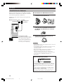
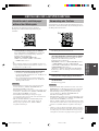
■ Connecting the AM loop antenna
1 Set up the AM loop antenna, then connect it
to the terminals on this unit.
2 Press and hold the tab to insert the AM loop
antenna lead wires into the AM ANT and
GND terminals.
3 Orient the AM loop antenna for the best
reception.
Notes
• The AM loop antenna should be placed away from this unit.
• The AM loop antenna should always be connected, even if an
outdoor AM antenna is connected to this unit.
• A properly installed outdoor antenna provides clearer
reception than an indoor one. If you experience poor reception
quality, an outdoor antenna may improve the quality. Consult
the nearest authorized YAMAHA dealer or service center
about the outdoor antennas.
FREQUENCY STEP switch
(Asia and General models only)
Because the interstation frequency spacing differs in
different areas, set the FREQUENCY STEP switch
(locating on the rear panel) according to the frequency
spacing in your area.
• North, Central and South America: 100 kHz/10 kHz
• Other areas: 50 kHz/9 kHz
Before setting this switch, disconnect this unit’s AC
power cord from the wall outlet.
Ground (GND terminal)
For maximum safety and minimum
interference, connect the antenna GND
terminal to a good earth ground. A good
earth ground is a metal stake driven into
moist earth.
Indoor FM
antenna
(included)
AM loop antenna
(included)
Connecting the antennas
Both AM and FM indoor antennas are included with this
unit. In general, these antennas should provide sufficient
signal strength.
Connect each antenna correctly to the designated
terminals.
CONNECTIONS
D
EO TUNER
AM
ANT
GND
FM
ANT
MONITOR
OUT
75Ω UNBAL.
100 kHz/10kHz
50 kHz/ 9kHz
FM/AM
FREQUENCY STEP
RX-V350_WD06070_EN.p65 1/19/04, 6:43 PM12

13
English
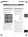
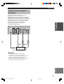
PREPARATION
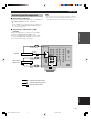
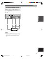
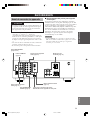
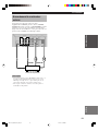
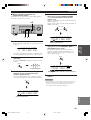
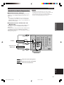
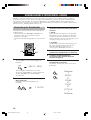
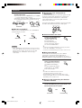
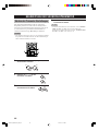
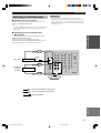
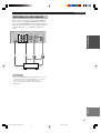
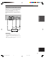
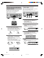
Connecting an external decoder
This unit is equipped with 6 additional input jacks
(FRONT left and right, CENTER, SURROUND left and
right and SUBWOOFER) for discrete multi-channel input
from a component equipped with a multi-channel decoder
and 6 channel output jacks such as a DVD/Super Audio
CD player.
Notes
• When you select 6CH INPUT as the input source, this unit
automatically turns off the digital sound field processor, and
you cannot select sound field programs.
• When headphones are used, only front L/R channels are
output.
DIGITAL
INPUT
AUDIO VIDEO TUNER
6CH INPUT
L
DVD
R
FRONT
SURROUND
SUB
WOOFER
CENTER
CD
COAX AL
DTV
/CBL
AM
ANT
GND
75Ω UNBAL.
V-AUX
3
L R
LR
SUBWOOFER FRONT
CENTER SURROUND
SUBWOOFER
CENTER SURROUND
CONNECTIONS
DVD/Super Audio CD player
RX-V350_WD06070_EN.p65 1/19/04, 6:43 PM13

14
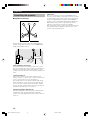
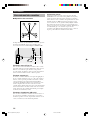
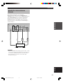
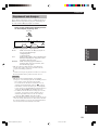
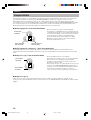
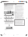
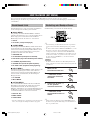
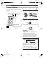
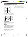
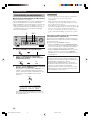
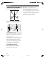
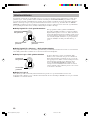
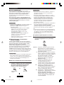
Connecting the speakers
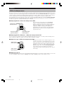
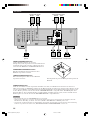
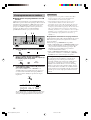
■ Speaker placement
60˚
30˚
FL
FR
C
SL
SR
SR
80˚
SL
The speaker layout above shows the standard ITU-R
speaker setting. You can use it to enjoy CINEMA DSP,
multi-channel audio sources.
1.8 m (6 ft)
Front speakers (FR and FL)
The front speakers are used for the main source sound
plus effect sounds. Place these speakers an equal distance
from the ideal listening position. The distance of each
speaker from each side of the video monitor should be the
same.
Center speaker (C)
The center speaker is for the center channel sounds
(dialog, vocals, etc.). If for some reason it is not practical
to use a center speaker, you can do without it.
Best results, however, are obtained with the full system.
Align the front face of the center speaker with the front
face of your video monitor. Place the speaker centrally
between the front speakers and as close to the monitor as
possible, such as directly over or under it.
Surround speakers (SR and SL)
The surround speakers are used for effect and surround
sounds. Place these speakers behind your listening
position, facing slightly inwards, about 1.8 m (6 ft) above
the floor.
CONNECTIONS
Subwoofer
The use of a subwoofer, such as the YAMAHA Active
Servo Processing Subwoofer System, is effective not only
for reinforcing bass frequencies from any or all channels,
but also for high fidelity reproduction of the LFE (low -
frequency effect) channel included in Dolby Digital and
DTS software. The position of the subwoofer is not so
critical, because low bass sounds are not highly
directional. But it is better to place the subwoofer near the
front speakers. Turn it slightly toward the center of the
room to reduce wall reflections.
RX-V350_WD06070_EN.p65 1/19/04, 6:43 PM14

15
English
PREPARATION
CONNECTIONS
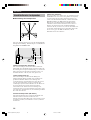
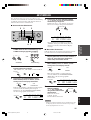
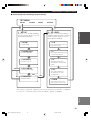
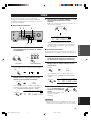
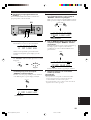
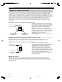
■ Speaker connections
Be sure to connect the left channel (L), right channel (R), “+” (red) and “–” (black) properly. If the connections are
faulty, no sound will be heard from the speakers, and if the polarity of the speaker connections is incorrect, the sound
will be unnatural and lack bass.
CAUTION
• Use speakers with the specified impedance shown on the rear panel of this unit.
• Before connecting the speakers, make sure that the power of this unit is off.
• Do not let the bare speaker wires touch each other or do not let them touch any metal part of this unit. This could
damage this unit and/or speakers.
• Use magnetically shielded speakers. If this type of speakers still creates the interference with the monitor, place
the speakers away from the monitor.
Connecting to the FRONT A SPEAKERS terminals
A speaker cord is actually a pair of insulated cables running side by side. One cable is colored or shaped differently,
perhaps with a stripe, groove or ridges. Connect the striped (grooved, etc.) cable to the “+” (red) terminals on this unit
and your speaker. Connect the plain cable to the “–” (black) terminals.
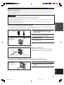
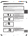
Connecting to the FRONT B, CENTER and SURROUND SPEAKERS terminals
1 Remove approximately 10 mm (3/8") of
insulation from the end of each of the
speaker cables.
2 Twist the exposed wires of the cable
together to prevent short circuits.
3 Unscrew the knob.
4 Insert one bare wire into the hole in the side
of each terminal.
5 Tighten the knob to secure the wire.
Banana plug connections
(With the exception of U.K., Europe and Asia models)
First, tighten the knob and then insert the banana plug
connector into the end of the corresponding terminal.
1 Press and open the tab.
2 Insert one bare wire into the hole of each
terminal.
3 Release the tab to secure the wire.
10 mm (3/8”)
12
Red: positive (+)
Black: negative (–)
3
4
5
Banana plug
(With the exception of U.K., Europe and Asia models)
3
1
2
Red: positive (+)
Black: negative (–)
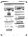
RX-V350_WD06070_EN.p65 1/19/04, 6:43 PM15

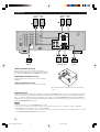
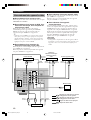
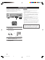
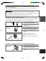
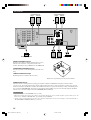
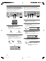
16
Subwoofer
system
Surround speaker
Center
speaker
Right
Front B speaker
SUBWOOFER jack
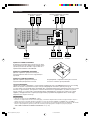
When using a subwoofer with built-in amplifier, including the YAMAHA Active Servo Processing Subwoofer System,
connect the input jack of the subwoofer system to this jack. This unit will direct low bass signals distributed from the
front, center and/or surround channels to this jack in accordance with your SPEAKER SET selections. The LFE (low-
frequency effect) signals generated when Dolby Digital or DTS is decoded are also directed to this jack in accordance
with your SPEAKER SET selections.
Notes
• The cut-off frequency of the SUBWOOFER jack is 90 Hz.
• If you do not use a subwoofer, allocate the signals to the front left and right speakers by changing the setting of “SOUND 1
SPEAKER SET” item “1D BASS” on the set menu to FRONT.
• Use the control on the subwoofer to adjust its volume level. You can also adjust the volume level by using this unit’s remote control
(see “SETTING THE SPEAKER LEVELS” on page 45).
Right Left
Front A speaker
Right Left Left
FRONT SPEAKERS terminals
You can connect up to two speaker systems to these
terminals. When using only one speaker system, connect
it to either of the FRONT A or the FRONT B terminals.
SURROUND SPEAKERS terminals
A surround speaker system can be connected to these
terminals.
CENTER SPEAKER terminals
A center speaker can be connected to these terminals.
CONNECTIONS
The diagram shows the speaker layout in the listening
room.
DIGITAL
INPUT
6CH INPUT AUDIO VIDEO TUNER SPEAKERS
AUDIO OUTPUT
L
DVD
R
LR
FRONT
SURROUND
SUB
WOOFER
CENTER
CD
DTV
/CBL
COAXIAL
OPTICAL
CD
IN
(PLAY)
MD
/CD-R
OUT
(REC)
DTV
/CBL
AM
ANT
FM
ANT
GND
75
Ω
UNBAL.
V-AUX
IN
VCR
OUT
SUB
WOOFER
MONITOR
OUT
DVD
3
2
1
L
FRONT
FRONT A OR B : 6
Ω
MIN. /SPEAKER CENTER : 6
Ω
MIN. /SPEAKER
A
B
R
L
SURROUND
R
L
FRONT
CENTER
R
SURROUND : 6
Ω
MIN. /SPEAKER
CLASS 2 WIRING
3
65
21
4
1
2
4
3
6
5
RX-V350_WD06070_EN.p65 1/19/04, 6:43 PM16

17
English
PREPARATION
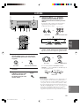
Connecting the power supply
cords
■ Connecting the AC power cord
Plug the power cord into an AC wall outlet.
■ VOLTAGE SELECTOR
(Asia and General models only)
The VOLTAGE SELECTOR on the rear panel of this unit
must be set for your local main voltage BEFORE
plugging into the AC main supply. Voltages are 110 V -
120 V/220 V - 240 V AC, 50/60 Hz.
VOLTAGE SELECTOR
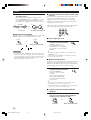
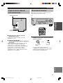
Turning on the power
When all connections are complete, turn on the power of
this unit.
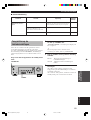
1 Press STANDBY/ON (POWER on the remote
control) to turn on the power of this unit.
The level of the volume, and then the current sound
field program name appear on the front panel
display.
or
Remote control
Front panel
(Asia and General models)
CONNECTIONS
L
REAR
U
RROUND
)
110V-120V
220V-240V
N
./SPEAKER
N
./SPEAKER
VOLTAGE
SELECTOR
PRESET/TUNING
EDIT
FM/AM A/B/C/D/E
NEXT
PRESET/TUNING
INPUT MODE 6CH INPUT
SET MENU
MEMORY
MAN'L/AUTO FM
TUNING MODE
AUTO/MAN'L MONO
RDS MODE/FREQ EON
PTY SEEK
MODE START
VOLUME
STEREO PROGRAM INPUT
EFFECT
CONTROL
BASS/TREBLE
STANDBY
/ON
PHONES
SILENT CINEMA
SPEAKERS
A/B/OFF
1
STANDBY
/ON
TEST
PROG PROG
STEREO
TUNER
CD MD/CD-R V-AUX 6CH IN
/DTS 6.1/5.1 NIGHT SLEEP
DVD D-TV/CBL VCR POWER
PRESET
A/B/C/D/E
VOLUME
1
POWER
RX-V350_WD06070_EN.p65 1/19/04, 6:43 PM17

18
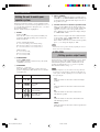
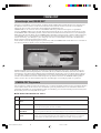
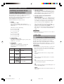
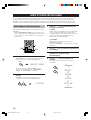
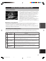
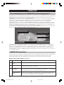
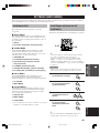
Using the basic menu
Use the remote control to make adjustments.
• Press SPEAKERS A/B/OFF on the front panel to select
the front speakers you want to use.
• Make sure you disconnect headphones from this unit.
1 Press SET MENU.
“BASIC MENU” appears on the front panel display.
If the front panel display changes to show anything
other than “BASIC MENU”, press SET MENU until
it displays “BASIC MENU”.
2 Press – / + to enter into the BASIC menu.
“1 SETUP” appears on the front panel display.
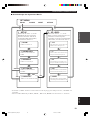
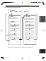
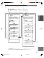
BASIC SYSTEM SETTINGS
The “BASIC” menu allows you to set some of the basic “SOUND” menu parameters with a minimum of effort. If you
wish to configure the unit more precisely to suit your listening environment, use the more detailed parameters from the
“SOUND” menu instead of those under the “BASIC” menu (See page 40). Altering any parameters in the BASIC menu
will reset all parameters in the “SOUND” menu.
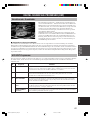
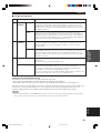
3 Press u / d to change the display to the
setting you want to alter.
1 SETUP
Changes the speaker and amplifier settings to suit the
size of the room you are using. Refer to “Setting the
unit to match your speaker system” on page 20 for
more information.
2 SP LEVEL
Adjusts the output levels of the speakers.
Refer to “SP LEVEL” on page 20 for more
information.
4 Press – / + to enter the desired setting mode.
5 Change the unit settings to suit your
listening environment.
6 Press u / d to exit from the set menu.
The front panel display changes in the following
order:
BASIC MENU
1 SETUP
↑
BASIC
↓↑
SOUND
↓↑
INPUT
↓↑
OPTION
↓
Exit
Exit
TEST
PROG PROG
STEREO
LEVEL
SET MENU
MUTE
VOLUME
VOLUME
1
2,4
3,6
SET MENU
RX-V350_WD06070_EN.p65 1/19/04, 6:44 PM18
La pagina sta caricando ...
La pagina sta caricando ...
La pagina sta caricando ...
La pagina sta caricando ...
La pagina sta caricando ...
La pagina sta caricando ...
La pagina sta caricando ...
La pagina sta caricando ...
La pagina sta caricando ...
La pagina sta caricando ...
La pagina sta caricando ...
La pagina sta caricando ...
La pagina sta caricando ...
La pagina sta caricando ...
La pagina sta caricando ...
La pagina sta caricando ...
La pagina sta caricando ...
La pagina sta caricando ...
La pagina sta caricando ...
La pagina sta caricando ...
La pagina sta caricando ...
La pagina sta caricando ...
La pagina sta caricando ...
La pagina sta caricando ...
La pagina sta caricando ...
La pagina sta caricando ...
La pagina sta caricando ...
La pagina sta caricando ...
La pagina sta caricando ...
La pagina sta caricando ...
La pagina sta caricando ...
La pagina sta caricando ...
La pagina sta caricando ...
La pagina sta caricando ...
La pagina sta caricando ...
La pagina sta caricando ...
La pagina sta caricando ...
La pagina sta caricando ...
La pagina sta caricando ...
La pagina sta caricando ...
La pagina sta caricando ...
La pagina sta caricando ...
La pagina sta caricando ...
La pagina sta caricando ...
La pagina sta caricando ...
La pagina sta caricando ...
La pagina sta caricando ...
La pagina sta caricando ...
La pagina sta caricando ...
La pagina sta caricando ...
La pagina sta caricando ...
La pagina sta caricando ...
La pagina sta caricando ...
La pagina sta caricando ...
La pagina sta caricando ...
La pagina sta caricando ...
La pagina sta caricando ...
La pagina sta caricando ...
La pagina sta caricando ...
La pagina sta caricando ...
La pagina sta caricando ...
La pagina sta caricando ...
La pagina sta caricando ...
La pagina sta caricando ...
La pagina sta caricando ...
La pagina sta caricando ...
La pagina sta caricando ...
La pagina sta caricando ...
La pagina sta caricando ...
La pagina sta caricando ...
La pagina sta caricando ...
La pagina sta caricando ...
La pagina sta caricando ...
La pagina sta caricando ...
La pagina sta caricando ...
La pagina sta caricando ...
La pagina sta caricando ...
La pagina sta caricando ...
La pagina sta caricando ...
La pagina sta caricando ...
La pagina sta caricando ...
La pagina sta caricando ...
La pagina sta caricando ...
La pagina sta caricando ...
La pagina sta caricando ...
La pagina sta caricando ...
La pagina sta caricando ...
La pagina sta caricando ...
La pagina sta caricando ...
La pagina sta caricando ...
La pagina sta caricando ...
La pagina sta caricando ...
La pagina sta caricando ...
La pagina sta caricando ...
La pagina sta caricando ...
La pagina sta caricando ...
La pagina sta caricando ...
La pagina sta caricando ...
La pagina sta caricando ...
La pagina sta caricando ...
La pagina sta caricando ...
La pagina sta caricando ...
La pagina sta caricando ...
La pagina sta caricando ...
La pagina sta caricando ...
La pagina sta caricando ...
La pagina sta caricando ...
La pagina sta caricando ...
La pagina sta caricando ...
La pagina sta caricando ...
La pagina sta caricando ...
La pagina sta caricando ...
La pagina sta caricando ...
La pagina sta caricando ...
La pagina sta caricando ...
La pagina sta caricando ...
La pagina sta caricando ...
La pagina sta caricando ...
La pagina sta caricando ...
La pagina sta caricando ...
La pagina sta caricando ...
La pagina sta caricando ...
La pagina sta caricando ...
La pagina sta caricando ...
La pagina sta caricando ...
La pagina sta caricando ...
La pagina sta caricando ...
La pagina sta caricando ...
La pagina sta caricando ...
La pagina sta caricando ...
La pagina sta caricando ...
La pagina sta caricando ...
La pagina sta caricando ...
La pagina sta caricando ...
La pagina sta caricando ...
La pagina sta caricando ...
La pagina sta caricando ...
La pagina sta caricando ...
La pagina sta caricando ...
La pagina sta caricando ...
La pagina sta caricando ...
La pagina sta caricando ...
La pagina sta caricando ...
La pagina sta caricando ...
La pagina sta caricando ...
La pagina sta caricando ...
La pagina sta caricando ...
La pagina sta caricando ...
La pagina sta caricando ...
La pagina sta caricando ...
La pagina sta caricando ...
La pagina sta caricando ...
La pagina sta caricando ...
La pagina sta caricando ...
La pagina sta caricando ...
La pagina sta caricando ...
La pagina sta caricando ...
La pagina sta caricando ...
La pagina sta caricando ...
La pagina sta caricando ...
La pagina sta caricando ...
La pagina sta caricando ...
La pagina sta caricando ...
La pagina sta caricando ...
La pagina sta caricando ...
La pagina sta caricando ...
La pagina sta caricando ...
La pagina sta caricando ...
La pagina sta caricando ...
La pagina sta caricando ...
La pagina sta caricando ...
La pagina sta caricando ...
La pagina sta caricando ...
La pagina sta caricando ...
La pagina sta caricando ...
La pagina sta caricando ...
La pagina sta caricando ...
La pagina sta caricando ...
La pagina sta caricando ...
La pagina sta caricando ...
La pagina sta caricando ...
La pagina sta caricando ...
La pagina sta caricando ...
La pagina sta caricando ...
La pagina sta caricando ...
La pagina sta caricando ...
La pagina sta caricando ...
La pagina sta caricando ...
La pagina sta caricando ...
La pagina sta caricando ...
La pagina sta caricando ...
La pagina sta caricando ...
La pagina sta caricando ...
La pagina sta caricando ...
La pagina sta caricando ...
La pagina sta caricando ...
La pagina sta caricando ...
La pagina sta caricando ...
La pagina sta caricando ...
La pagina sta caricando ...
La pagina sta caricando ...
La pagina sta caricando ...
La pagina sta caricando ...
La pagina sta caricando ...
La pagina sta caricando ...
La pagina sta caricando ...
La pagina sta caricando ...
La pagina sta caricando ...
La pagina sta caricando ...
La pagina sta caricando ...
La pagina sta caricando ...
La pagina sta caricando ...
La pagina sta caricando ...
La pagina sta caricando ...
La pagina sta caricando ...
La pagina sta caricando ...
La pagina sta caricando ...
La pagina sta caricando ...
La pagina sta caricando ...
La pagina sta caricando ...
La pagina sta caricando ...
La pagina sta caricando ...
La pagina sta caricando ...
La pagina sta caricando ...
La pagina sta caricando ...
La pagina sta caricando ...
La pagina sta caricando ...
La pagina sta caricando ...
La pagina sta caricando ...
La pagina sta caricando ...
La pagina sta caricando ...
La pagina sta caricando ...
La pagina sta caricando ...
La pagina sta caricando ...
La pagina sta caricando ...
La pagina sta caricando ...
La pagina sta caricando ...
La pagina sta caricando ...
La pagina sta caricando ...
La pagina sta caricando ...
La pagina sta caricando ...
La pagina sta caricando ...
La pagina sta caricando ...
La pagina sta caricando ...
La pagina sta caricando ...
La pagina sta caricando ...
La pagina sta caricando ...
La pagina sta caricando ...
La pagina sta caricando ...
La pagina sta caricando ...
La pagina sta caricando ...
La pagina sta caricando ...
La pagina sta caricando ...
La pagina sta caricando ...
La pagina sta caricando ...
La pagina sta caricando ...
La pagina sta caricando ...
La pagina sta caricando ...
La pagina sta caricando ...
La pagina sta caricando ...
La pagina sta caricando ...
La pagina sta caricando ...
La pagina sta caricando ...
La pagina sta caricando ...
La pagina sta caricando ...
La pagina sta caricando ...
La pagina sta caricando ...
La pagina sta caricando ...
La pagina sta caricando ...
La pagina sta caricando ...
La pagina sta caricando ...
La pagina sta caricando ...
La pagina sta caricando ...
La pagina sta caricando ...
La pagina sta caricando ...
La pagina sta caricando ...
La pagina sta caricando ...
La pagina sta caricando ...
La pagina sta caricando ...
La pagina sta caricando ...
La pagina sta caricando ...
La pagina sta caricando ...
La pagina sta caricando ...
La pagina sta caricando ...
La pagina sta caricando ...
La pagina sta caricando ...
La pagina sta caricando ...
La pagina sta caricando ...
La pagina sta caricando ...
La pagina sta caricando ...
La pagina sta caricando ...
La pagina sta caricando ...
La pagina sta caricando ...
La pagina sta caricando ...
La pagina sta caricando ...
La pagina sta caricando ...
La pagina sta caricando ...
La pagina sta caricando ...
La pagina sta caricando ...
La pagina sta caricando ...
La pagina sta caricando ...
La pagina sta caricando ...
La pagina sta caricando ...
La pagina sta caricando ...
La pagina sta caricando ...
La pagina sta caricando ...
La pagina sta caricando ...
La pagina sta caricando ...
La pagina sta caricando ...
La pagina sta caricando ...
La pagina sta caricando ...
-
 1
1
-
 2
2
-
 3
3
-
 4
4
-
 5
5
-
 6
6
-
 7
7
-
 8
8
-
 9
9
-
 10
10
-
 11
11
-
 12
12
-
 13
13
-
 14
14
-
 15
15
-
 16
16
-
 17
17
-
 18
18
-
 19
19
-
 20
20
-
 21
21
-
 22
22
-
 23
23
-
 24
24
-
 25
25
-
 26
26
-
 27
27
-
 28
28
-
 29
29
-
 30
30
-
 31
31
-
 32
32
-
 33
33
-
 34
34
-
 35
35
-
 36
36
-
 37
37
-
 38
38
-
 39
39
-
 40
40
-
 41
41
-
 42
42
-
 43
43
-
 44
44
-
 45
45
-
 46
46
-
 47
47
-
 48
48
-
 49
49
-
 50
50
-
 51
51
-
 52
52
-
 53
53
-
 54
54
-
 55
55
-
 56
56
-
 57
57
-
 58
58
-
 59
59
-
 60
60
-
 61
61
-
 62
62
-
 63
63
-
 64
64
-
 65
65
-
 66
66
-
 67
67
-
 68
68
-
 69
69
-
 70
70
-
 71
71
-
 72
72
-
 73
73
-
 74
74
-
 75
75
-
 76
76
-
 77
77
-
 78
78
-
 79
79
-
 80
80
-
 81
81
-
 82
82
-
 83
83
-
 84
84
-
 85
85
-
 86
86
-
 87
87
-
 88
88
-
 89
89
-
 90
90
-
 91
91
-
 92
92
-
 93
93
-
 94
94
-
 95
95
-
 96
96
-
 97
97
-
 98
98
-
 99
99
-
 100
100
-
 101
101
-
 102
102
-
 103
103
-
 104
104
-
 105
105
-
 106
106
-
 107
107
-
 108
108
-
 109
109
-
 110
110
-
 111
111
-
 112
112
-
 113
113
-
 114
114
-
 115
115
-
 116
116
-
 117
117
-
 118
118
-
 119
119
-
 120
120
-
 121
121
-
 122
122
-
 123
123
-
 124
124
-
 125
125
-
 126
126
-
 127
127
-
 128
128
-
 129
129
-
 130
130
-
 131
131
-
 132
132
-
 133
133
-
 134
134
-
 135
135
-
 136
136
-
 137
137
-
 138
138
-
 139
139
-
 140
140
-
 141
141
-
 142
142
-
 143
143
-
 144
144
-
 145
145
-
 146
146
-
 147
147
-
 148
148
-
 149
149
-
 150
150
-
 151
151
-
 152
152
-
 153
153
-
 154
154
-
 155
155
-
 156
156
-
 157
157
-
 158
158
-
 159
159
-
 160
160
-
 161
161
-
 162
162
-
 163
163
-
 164
164
-
 165
165
-
 166
166
-
 167
167
-
 168
168
-
 169
169
-
 170
170
-
 171
171
-
 172
172
-
 173
173
-
 174
174
-
 175
175
-
 176
176
-
 177
177
-
 178
178
-
 179
179
-
 180
180
-
 181
181
-
 182
182
-
 183
183
-
 184
184
-
 185
185
-
 186
186
-
 187
187
-
 188
188
-
 189
189
-
 190
190
-
 191
191
-
 192
192
-
 193
193
-
 194
194
-
 195
195
-
 196
196
-
 197
197
-
 198
198
-
 199
199
-
 200
200
-
 201
201
-
 202
202
-
 203
203
-
 204
204
-
 205
205
-
 206
206
-
 207
207
-
 208
208
-
 209
209
-
 210
210
-
 211
211
-
 212
212
-
 213
213
-
 214
214
-
 215
215
-
 216
216
-
 217
217
-
 218
218
-
 219
219
-
 220
220
-
 221
221
-
 222
222
-
 223
223
-
 224
224
-
 225
225
-
 226
226
-
 227
227
-
 228
228
-
 229
229
-
 230
230
-
 231
231
-
 232
232
-
 233
233
-
 234
234
-
 235
235
-
 236
236
-
 237
237
-
 238
238
-
 239
239
-
 240
240
-
 241
241
-
 242
242
-
 243
243
-
 244
244
-
 245
245
-
 246
246
-
 247
247
-
 248
248
-
 249
249
-
 250
250
-
 251
251
-
 252
252
-
 253
253
-
 254
254
-
 255
255
-
 256
256
-
 257
257
-
 258
258
-
 259
259
-
 260
260
-
 261
261
-
 262
262
-
 263
263
-
 264
264
-
 265
265
-
 266
266
-
 267
267
-
 268
268
-
 269
269
-
 270
270
-
 271
271
-
 272
272
-
 273
273
-
 274
274
-
 275
275
-
 276
276
-
 277
277
-
 278
278
-
 279
279
-
 280
280
-
 281
281
-
 282
282
-
 283
283
-
 284
284
-
 285
285
-
 286
286
-
 287
287
-
 288
288
-
 289
289
-
 290
290
-
 291
291
-
 292
292
-
 293
293
-
 294
294
-
 295
295
-
 296
296
-
 297
297
-
 298
298
-
 299
299
-
 300
300
-
 301
301
-
 302
302
-
 303
303
-
 304
304
-
 305
305
-
 306
306
-
 307
307
-
 308
308
-
 309
309
-
 310
310
-
 311
311
-
 312
312
-
 313
313
-
 314
314
-
 315
315
-
 316
316
-
 317
317
-
 318
318
-
 319
319
-
 320
320
-
 321
321
-
 322
322
-
 323
323
-
 324
324
-
 325
325
-
 326
326
-
 327
327
-
 328
328
-
 329
329
-
 330
330
-
 331
331


Yamaha RX-V350 Manuale del proprietario
- Categoria
- Ricevitori AV
- Tipo
- Manuale del proprietario
in altre lingue
- English: Yamaha RX-V350 Owner's manual
- français: Yamaha RX-V350 Le manuel du propriétaire
- Deutsch: Yamaha RX-V350 Bedienungsanleitung
- русский: Yamaha RX-V350 Инструкция по применению
- Nederlands: Yamaha RX-V350 de handleiding
- dansk: Yamaha RX-V350 Brugervejledning
- svenska: Yamaha RX-V350 Bruksanvisning
- Türkçe: Yamaha RX-V350 El kitabı
- română: Yamaha RX-V350 Manualul proprietarului
Documenti correlati
-
Yamaha HTR-6160 Manuale del proprietario
-
-
Yamaha RX-V459 Manuale del proprietario
-
-
-
-
-
Yamaha RX-V650 Manuale del proprietario
-