La pagina si sta caricando...

DS80SC60-001 LBT80336 IS7525-AA
I
Manuale di installazione
Installation Manual
C302
Centralina monozona
Sin
g
le zone control
p
anel
GB

C302
2/24
COPYRIGHT
Questo software e' prodotto da ELKRON S.p.A. ed e' protetto dalle leggi italiane sul copyright e da tutte le
applicabili leggi nazionali. Percio' questo software deve essere considerato come ogni altro materiale
comprensivo di copyright (ad esempio libri o cassette musicali) ad eccezione del fatto che l'utente puo' (a)
fare una copia del software al solo scopo di backup oppure (b) installare il software su un singolo hard disk
tenendo l'originale solo per backup. Non e' permesso copiare il software o qualsiasi materiale scritto che lo
accompagna.
GARANZIA LIMITATA
La ELKRON S.p.A. garantisce che (a) il software si comportera' in accordo con quanto descritto nei manuali
che accompagnano il prodotto (b) i dischetti di installazione del prodotto saranno esenti da difetti se
rispettate le normali regole di utilizzo.
IN NESSUN CASO ELKRON S.p.A. O I SUOI FORNITORI SARANNO RESPONSABILI PER DANNI DI
ALCUN GENERE (INCLUSI SENZA LIMITAZIONI DANNI PER PERDITA DI PROFITTI, PER
INTERRUZIONE DI SERVIZIO O ALTRA PERDITA PECUNIARIA) CHE POTREBBERO DERIVARE
DALL'USO NON CORRETTO O DALLA IMPOSSIBILITA' DI USO DEL PRODOTTO SOFTWARE.
Questa licenza e' governata dalle leggi italiane
AVVERTENZA : Il computer dedicato alla gestione della visualizzazione delle mappe non dovrebbe essere
utilizzato per altri scopi, in quanto altri programmi potrebbero diminuire le prestazioni del computer durante
l’esecuzione di procedure particolarmente delicate come l’acquisizione dati dalle centrali AREA54 o la
visualizzazione delle mappe grafiche.
La ELKRON S.p.A. declina ogni responsabilità in caso di malfunzionamento del proprio software nel caso in
cui il computer non soddisfi ai requisiti minimi richiesti oppure il programma di visualizzazione mappe venga
utilizzato unitamente ad altri programmi non di sistema (giochi, Internet, animazioni,…)
COPYRIGHT
This software is produced by ELKRON S.p.A. and is protected by Italian copyright laws and by all other
applicable national laws. Therefore this software, like all other material (such as books or music cassettes),
must be taken to include copyright, with the exception that users may (a) make a copy of the software solely
for backup purposes or (b) install the software on a single hard disk, keeping the original copy as a backup.
Copying the software or any accompanying written material is prohibited.
LIMITED WARRANTY
ELKRON S.p.A. warrants that (a) the software will operate as described in the manuals that accompany the
product and that (b) the product installation diskettes are free of defects if standard norms of usage are
respected.
IN NO CASE SHALL ELKRON OR ITS SUPPLIERS BE LIABLE FOR DAMAGE OF ANY KIND
(INCLUDING, WITHOUT LIMITS, DAMAGE RESULTING FROM LOSS OF EARNINGS, DISRUPTION TO
SERVICE OR OTHER FINANCIAL LOSS) THAT COULD ARISE FROM IMPROPER USE OR
UNUSABILITY OF THE SOFTWARE PRODUCT.
This licence is governed by Italian laws.
WARNING : The computer dedicated to the management of display of the maps must not be used for other
purposes, as other programs could impair the performance of the computer during the execution of
particularly delicate procedures such as the acquisition of data from the AREA54 Control Panels or the
display of graphical maps.
Elkron S.p.A. disclaims all responsibility in the event of malfunction of its software if the computer
does not possess the minimum system requirements or if the Map Viewing program is used
together with other non-system programs (games, internet, animations, etc.).

C302
3/24
Indici
1 Generalità..................................................................................................................................4
2 Funzionamento..........................................................................................................................5
3 Dimensioni e fissaggi.................................................................................................................6
4 Caratteristiche tecniche.............................................................................................................7
5 Descrizione scheda e morsettiera .............................................................................................8
5.1 Descrizione jumper.................................................................................................................9
6 Installazione...............................................................................................................................9
7 Collegamenti centralina...........................................................................................................10
7.1 Schemi di collegamento indicativi........................................................................................ 10
7.2 Impianto tipo con elettromagneti E/401 – E/402................................................................11
7.3 Impianto tipo con elettromagneti E/401 – E/402 con contatti chiusi per il controllo porte..11
7.4 Impianto tipo con elettromagneti E/405 per il controllo dello sgancio porta.......................11
7.5 Collegamenti ad elettromagneti.........................................................................................12
7.6 Collegamenti a rivelatori di gas..........................................................................................12
7.7 Collegamento ad RG54 – Un dispositivo...........................................................................13
7.8 Collegamento ad RG54 – 2 o più dispositivi......................................................................13
Index
1 General Information....................................................................................................................14
2 Operation....................................................................................................................................15
3 Dimensions and drilling template................................................................................................16
4 Specifications..............................................................................................................................17
5 Card and terminal board description............................................................................................20
5.1 Jumper description.............................................................................................................19
6 Installation...................................................................................................................................19
7 Control panel connection………………………………....………..................................................22
7.1 Indicative connecting diagrams............................................................................................20
7.2 Standard system with E/401 – E/402 electromagnets.......................................................21
7.3
Standard system with E/401 – E/402 electromagnets with closed contacts for the door check
......................21
7.4 Standard system with E/405 electromagnets for the door release check..........................21
7.5 Connections to electromagnets .........................................................................................22
7.6 Connections to gas detectors ............................................................................................22
7.7 Connection to RG54 – One device....................................................................................23
7.8 Connection to RG54 – two or more devices......................................................................23

C302
4/24
1 Generalità
La Centralina monozona a Microprocessore di Rivelazione Fumo e Termico C/302 è
stata realizzata per risolvere al meglio la problematica inerente al controllo e al pilotaggio
di porte tagliafuoco.
Una importante funzione per la sicurezza dell’impianto è stata inserita all’interno della
Centralina per controllarne lo sgancio e con l’effettiva chiusura della porta.
Tramite un contatto chiuso posto sulla porta, la Centrale con un segnale di Anomalia ne
avvisa la mancata chiusura, oppure nel caso che la porta dopo essersi chiusa dopo un
Allarme venga aperta, in questi casi la Centrale comunica sempre con un segnale di
Anomalia.
L’altra opportunità è quella di collegare degli Elettromagneti serie nuova per il controllo
dello sgancio avvenuto.
Gli Elettromagneti serie E/405 sono abilitati tramite un contatto REED posto su di un
circuito a segnalarne l’avvenuto sgancio Elettrico e Meccanico avvenuto nel momento
dell’Allarme.
Un’altra funzione importante della C/302 è quella dello sblocco degli Elettromagneti da
istantaneo a ritardabile, questo lo si può impostare tramite ponticello posto sulla stessa.
Lo sblocco del Ritardo per la chiusura delle porte potrà essere con un ritardo di 15 secondi
oppure di 30 secondi, nello stesso tempo si commutano le uscite di ripetizione Allarme e si
attivano le indicazioni Ottiche /Acustiche di cui dispone.
La C/302 è in grado di alimentare e pilotare n° 6 Elettromagneti per il blocco delle porte,
una uscita dedicata controlla e gestisce al meglio le batterie per il sostenimento in caso di
mancanza della fonte primaria di alimentazione.
La Rivelazione doppia della Centralina permette di controllare in modo idoneo i due
parametri di un incendio FUMO e CALORE.
La Rivelazione interna della Centralina per l’incendio è delegata ad un sensore di fumo
funzionante sul principio dell’effetto TYNDALL, mentre per la Rivelazione del Calore viene
effettuata tramite una sonda elettronica Termica.
La Centralina gestisce e controlla una Linea di Rivelazione esterna nella quale si possono
collegare altri tipi di rivelatori SIRA: di fumo - termici - gas - fiamma (max 15).
Per la gestione e monitoraggio di eventi attivi del tipo, Anomalie da linea di rivelazione,
Anomalie di controllo porte e controllo sgancio magneti, linea attivata o esclusa, la
Centralina le visualizza tramite una serie di Led e acusticamente tramite un buzzer interno.
Tutti gli eventi di Allarme sono evidenziati da indicazioni Ottiche, tramite delle spie
rettangolari di colore rosso trasparente e con una scritta FIRE, sono poste ai due fianchi e
si illuminano in caso di Allarme, mentre un buzzer a suono differenziato ne segnala la
parte acustica.
La Centralina può informare sullo stato di Allarme altre apparecchiature avendo a bordo
un relè a uno scambio con contatti liberi, e una uscita open collector.
La C/302 è dotata di una morsettiera di collegamento da e verso il campo.
Nota: (le batterie NON possono essere alloggiate all’interno della centralina).

C302
5/24
2 Funzionamento
L’interruttore posto in posizione “1 “ la Centralina si trova nello stadio di non operatività
‘Esclusa’.
-Led Verde spento, linea di rivelazione spenta e gli elettromagneti NON sono alimentati,
mentre le alimentazioni verso il campo e verso le batterie sono attive.
-Agendo sull’interruttore e posizionandolo sullo ‘0’ il Led Verde si accende, la linea di
rivelazione ed gli elettromagneti vengono alimentati, e dopo circa 4 secondi un breve
segnale acustico segnala il funziona mento della centralina.
-Se l’opzione, controllo porta Porta tagliafuoco è attivata (ponte J2 , pin 5-6 - ON ), la
Centralina esegue tale controllo e nel caso la porta non sia agganciata all’elettromagnete
oppure il cavo è interrotto, la centralina provvede a segnalare in modo visivo ed acustico
con l’accensione del Led di guasto a del Buzzer con suono intermittente, ne viene attivata
l’uscita Open - collector relativa morsetto n° 9.
Per ripristinare l’evento, agganciare la porta all’Elettromagnete e controllarne la
connessione.
Connessione per il controllo delle porte al “ morsetto N°17 tramite un contatto a chiuso
a negativo, e con porta agganciate all’elettromagnete”.
- In caso di allarme con tempo Impostato a ( 0 ), la centralina toglie alimentazione agli
Elettromagneti, eccita il relè di Allarme attiva la ripetizione Negativa, accende il led rosso e
la lampada in modo continuo, il buzzer emette un suono continuo.
L’evento di allarme della Rivelazione Interna NON viene memorizzato mentre l’allarme da
Linea di Rivelazione Esterna, oppure da Rivelazione Termica interna viene memorizzato.
Per ripristinare il normale funzionamento si deve agire sull’interruttore portandolo sulla
posizione ( 1 ) o dal reset esterno, morsetto n° 12.
-In caso di allarme e ritardo sgancio Elettromagneti con tempo di:
- La Centralina toglie alimentazione agli Elettromagneti in funzione al tempo selezionato,
mentre immediatamente eccita il relè di Allarme, accende il Led Rosso, la Lampada ed il
buzzer funzionano in modo oscillante, per indicare che il Timer è in funzione, scaduto il
tempo la lampada ed il buzzer si attivano in modo continuo.
L’evento di Allarme dalla Camera di Rivelazione NON viene memorizzato mentre l’Allarme
da Linea di Rivelazione esterna o da Rivelazione Termica viene memorizzato.
Per ripristinare il normale funzionamento si deve agire sull’interruttore portandolo sulla
posizione ( 1 ) o dal reset esterno, morsetto n° 12.
- In caso di allarme e se è utilizzata la funzione di controllo Porta tagliafuoco, ( ponte J2 ,
pin 5-6 - ON ), la Centralina controlla tale segnale dopo aver sganciato l’Elettromagnete.
- Se la segnalazione di porta chiusa non arriva o se arriva dopo il tempo di circa 30
secondi, la centralina accende il Led Giallo in modo oscillate, ed il segnale acustico
diventa oscillante con la stessa frequenza, tale evento persiste fin quando l’evento di
Allarme sussiste o a chiusura della porta.
- In caso di Fault della Linea di Rivelazione per mancanza della resistenza di fine linea, il
Led Giallo ed il buzzer funzioneranno in modo oscillante con una frequenza minore.
-In caso di cortocircuito della Linea di Rivelazione, la centralina accende il Led Giallo in
modo fisso, il Led Verde si spegne ed il buzzer emetterà un suono continuo di
conseguenza la Linea di Rivelazione verrà disalimentata mentre gli Elettromagneti
rimangono alimentati.
-Tutti gli eventi provenienti dalla Linea di Rivelazione esterna sono memorizzati.
Per ripristinare il normale funzionamento si deve agire sull’interruttore portandolo sulla
posizione ( 1 ) o dal reset esterno, morsetto n° 12.

C302
6/24
- In caso di controllo Porta tagliafuoco attivo la Centralina controlla che la porta sia
agganciata all’Elettromagnete in caso di normale funzionamento, e che sia chiusa dopo un
tempo di circa 30 secondi nella condizione di allarme ed Elettromagneti sganciati.
In condizione di Allarme da Linea di Rivelazione e porta tagliafuoco non chiusa e
successivamente cortocircuito della Linea di Rivelazione, la Centralina spegne il Led
Verde e la Linea di Rivelazione esterna mentre la segnalazione del Led Rosso di Allarme
e la lampadina sono accesi in modo fisso mentre il Led di Fault ed il buzzer funzionano in
modo oscillante.
Acceso Funzionamento della Centralina (a seguito di un bip
dopo 4 secondi )
Led Verde Spento Centralina con Elettromagneti e Linea di
Rivelazione esclusi
Led Rosso Acceso fisso Presenza di allarme
Spento Linea Rivelazione Corretta
Lampeggiante Linea Rivelazione non Terminata + buzzer
intermittente
Led Giallo Acceso + Led verde
spento Linea Rivelazione in Corto + buzzer fisso
0 Centralina in Funzione
Interruttore 1
Centralina Esclusa , Led Verde Spento
Linea di Rivelazione ESTERNA Esclusa
Elettromagneti NON sono Alimentati
Alimentazioni verso il campo e verso le Batterie
sono presenti
3 Dimensioni e fissaggi
?5?
?
3?
?3?
0
1
?
?
??
Entrata cavi
diametro 19
Led Rosso
Led Verde
Led Giallo
Pulsante di
Reset
71 283
245
75
113
ø 5

C302
7/24
4 Caratteristiche tecniche
Tensione nominale della rete di alimentazione:…… 230 V
Frequenza nominale della rete di alimentazione:…. 50 Hz
Massimo assorbimento dell’apparecchio:…………. 100 mA
Fusibile di protezione 230 V (F1):……………………. Fusibile ritardato 5x20 T250 mA
Tensione secondaria stabilizzata:…………………… 24 VDC 300 mA
Rivelatore di fumo:……………………………………… Fusibile ritardato 5x20 T500 mA
Rivelatore termico:……………………………………… Effetto ottico tyndall
Allarme ottico:…………………………………………… Spie rosse poste sui 2 lati,
N° 1 lamp. 24 V 2 W
Allarme acustico:………………………………………... Buzzer
Temperatura di funzionamento:………………………. -10°C…..+50°C
Contatti relè scambio libero di allarme:………………. 1A max. 30 VDC
Uscita batterie tampone:………………………………. N° 2 Batterie da 12 V - max 1,2 Ah
Corrente di ricarica batterie:…………………………… 120 mA
Materiale del contenitore:……………………………… ABS autoestinguente UL94-V0
Colore:…………………………………………………… RAL 7032
Misure (mm):……………………………………………. 283 (L) – 113 (P) - 71 (H)
Peso:……………………………………………………... 700 g
Grado di protezione:…………………………………….. IP 32
NOTE:
• A monte dell’apparecchio collegare un interruttore magneto-termico
differenziale
• Per garantire la protezione dell’apparecchio contro infiltrazioni accidentali di
acqua e polvere utilizzare un passacavo con grado di protezione minimo IP32
e classe di infiammabilità 5V
• Per il collegamento dell’apparecchio alla rete elettrica utilizzare un cavo di
alimentazione che garantisca il doppio isolamento

C302
8/24
RE
+
SP
LD2
+
LD3
LD1
+
RP
1
BT+ BT- NC+27LR+ LR-E-
NF RA E+ NA C
F2
F1
M1
M2
Trasformatore
Buzzer
531
J2
426
000081
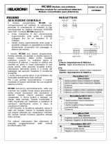
5 Descrizione scheda e morsettiera
DESCRIZIONE
M1 N Ingresso 230 V (Neutro)
Terra
F Ingresso 230 V (Fase)
M2BT+ Ingresso positivo batteria
BT- Ingresso negativo batteria
RA Rip. negativa di allarme max 100 mA
E- Negativo Elettromagneti
E+ Positivo Elettromagneti max. 300 mA
RP Rip.negativa anomalia porta max 100 mA
LR+ Positivo linea di rivelazione max 80 mA
LR- Negativo linea di rivelazione
RE Ingresso positivo Reset
+27 Positivo 27 VDC campo max 300 mA
NA Contatto NA relè allarme 1 A 30VDC
C Contatto C relè allarme 1 A 30VDC
NC Contatto NC relè allarme 1 A 30VDC
SP Segnale porta
F1 Fusibile protezione 250 mA
F2 Fusibile protezione 500 mA
J2 Jumper per ritardo sgancio elettromagneti

C302
9/24
5.1 Descrizione jumper
Ritardo elettromagneti: posizionare
i jumper su J2 per associare il ritardo
sgancio elettromagneti secondo la
tabella:
Posizionare il jumper 5-6 su J2 per impostare la
funzione di controllo porta
Nota:
L’alimentazione della centralina fornisce 300mA in totale su tutte le uscite. Resta a cura
dell’installatore il posizionamento delle apparecchiature sulle diverse uscite.
6 Installazione
Per ambienti con altezza massima della copertura /
soffitto fino a 6 metri posizionare l’apparecchio a
soffitto, distanziandolo 1 metro dalla parete in cui sia
presente la porta di ingresso (vedere figura a lato).
Per ambienti di altezze superiori a 6 metri ma non
superiori ai 12 metri si deve prevedere l’utilizzo di
un rivelatore esterno, collegato alla centrale C/302
ed installato sulla copertura.
La centrale C/302 dovrà essere installata ad
un’altezza pari alla metà dell’altezza della copertura
/ soffitto, distanziandola 1 metro dalla parete in cui
sia presente la porta di’ingresso. In tale caso dovrà
essere usata una staffatura per assicurare
l’installazione in posizione orizzontale (vedere
figura a lato).
Nota: in tutti i casi la centrale C/302 deve
sempre essere posizionata in orizzontale.
Ritardo Pos. jumper
1-2 3-4
0 s
15 s
30 s
Controllo porta 5-6
Attivo
Disattivo
Jumper presente
Jumper assente
Soffitto
Muro
laterale
000084
6 m
C/302
1 m
Porta
Soffitto
Muro
laterale
000083
12 m
6 m
C/302
BP212
1 m
Porta

C302
10/24
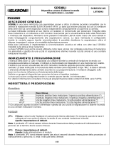
7 Collegamenti centralina
7.1 Schemi di collegamento indicativi
RE
+
SP
LD2
+
LD3
LD1
+
RP
1
BT+ BT- NC+27LR+ LR-E-
NF RA E+ NA C
F2
F1
M1
M2
Trasformatore
Buzzer
531
J2
426
000085
230 V - 50 Hz
ELETTROMAGNETI
SIRENA
RIVELATORI
24 V. d.c. 300 mA Max.
13
1
678
Rip. Neg. anomalia porta
34
125
24 V. d.c.
++-- +
-
Contatti NC posizionati sulle porte

C302
11/24
7.2 Impianto tipo con elettromagneti E/401 – E/402
RIVELATORE
Elettromagnete
mod. E/402
Elettromagnete
mod. E/402 Centralina
mod. C/302
7.3 Impianto tipo con elettromagneti E/401 – E/402 con contatti chiusi
per il controllo porte
RIVELATORE Centralina
mod. C/302
Elettromagnete
mod. E/402
Contatti NC per il
controllo porta
7.4 Impianto tipo con elettromagneti E/405 per il controllo dello sgancio
porta
RIVELATORE
Elettromagnete
mod. E/405
Centralina
mod. C/302

C302
12/24
7.5 Collegamenti ad elettromagneti
Questo elettromagnete è dotato di pulsante di sblocco. La linea degli elettromagneti deve
essere connessa in parallelo come rappresentato dal disegno.
Questo elettromagnete è dotato di pulsante di sblocco. Un contatto reed viene utilizzato
per il controllo dello sgancio. La linea degli elettromagneti deve essere connessa in
parallelo come rappresentato dal disegno.
7.6 Collegamenti a rivelatori di gas
LR+
+27
LR-
3 4
1 2 5
-
+
+ 3
6
5
4
2
1 LR+
+27
LR-
-
+
+7
6
1
8
-
+
+
LR+
+27
LR-
Schema di collegamento con rivelatore
di GAS RG/201 o RG/203IP (Max. 2)
Schema di collegamento con
rivelatore di GAS RG/203 (Max. 2)
Schema di collegamento con rivelatore
di GAS BPG/213 (Max. 2)
Resistenza di
Fine Linea
da 3,3 K
ohm
Resistenza di Fine Linea
da 3,3 Kohm
Resistenza di
Fine Linea
da 3,3 Kohm
ELETTROMAGNETE
mod. E/402
??0?>
46
E+ E-
C/302
Elettromagnete
E/402
ELETTROMAGNETE
mod. E/402
E+
E-
C/302
Elettromagnete
E/405
SP RP

C302
13/24
7.7 Collegamento ad RG54 – Un dispositivo
RE SPRP
1
BT+ BT- NC+27LR+ LR-E-
NF RA E+ NA C
F2
F1
M1
M2
Trasformatore
Buzzer
531
J2
426
000087
Sezione cavi 1mm2
Terra locale
8
4
1
3
2
6
5
7
+
+
-
-
10
9
Passacavo
P7 ON
P8 ON
7.8 Collegamento ad RG54 – 2 o più dispositivi
Il numero massimo di sensori RG54 collegabili è di 3.
M1
000088
N1
F1
F2
FBT-BT+ RA E+E- RP
J2
Buzzer
2
1
64
35
NARELR- +27 NCCSP
6
3
1
2
4
5
Sezione cavi 1mm2
-
+
-
+
Terra locale
10
8
7
9
Passacavo
M2
LR+
Trasformatore
+
2
1
7
4
3
5
6
-
+
-
9
8
10
Primo sensore
P7 ON
P8 ON
Ultimo sensore
P7 ON
P8 ON
3K3
Resistenza di fine linea

C302
14/24
1 General Information
The C/302 Microprocessor Smoke and heat detection single zone Control panel has
been developed to give an optimized solution to the need related to fire doors monitor and
control.
An important feature, useful for the system’s security, has been implemented in order to
drive the release action and verify the actual door closure.
The failure of the door closure is notified by means of FAULT signal.
Such a condition can be iniated by the doors monitoring circuit or can be caused by an
unsuccesful post alarm condition.
On the doors monitoring circuit is also possible to connect the Reed contact of the E/405
door holders; such a way allows to supervise the release command has been correctly
performed.
Another important feature of C/302 is to set the way to drive door holder, as here below:
• 0 second delay: door holder are unlock on alarm condition
• 15 seconds delay: door holder are unlock with 15 s delay after alarm notification;
alarm notification continues to be active
• 30 seconds delay: door holder are unlock with 30 s delay after alarm notification;
alarm notification continues to be active
During the time delay, alarm notification appliances (audible and visible) are activated in
pulsive way; at the end of countdown, the door holders are unlock and alarm notification
appliances switch to steady way.
C/302 is able to supply and control up to 6 Door holder for the door lock; a dedicated
output supervise the external batteries circuit.
The C/302 provides a built-in double technology detector (smoke and heat) which allows
to check both the main fire effect: smoke and heat.
The panel can be connected to an external detection circuit having a maximum of 15
detectors of different type (smoke, heat, flame, gas).
Trouble conditions (sucha detection line trouble, door contacts and door holders trouble)
and lines activation or exclusions are notified by means of LEDs and buzzer.
Alarm condictions are notified by means of red led, the visible “FIRE” windows, placed on
the both sides of the panel and the dedicated sound of the buzzer.
Alarm repetition form C relay allows to trasmit alarm to external notification appliances.
C/302 is equipped with a terminal block for the connection to and from the field.
Note: (the batteries CANNOT be housed inside the control module).

C302
15/24
2 Operation
The switch is set on position “1”, the Control panel is in the “Excluded” idle stage.
- The Green Led is off, the detection line is disabled and the door holders are NOT powered,
while the supplies to the field and to the batteries are active.
- By pressing the switch and setting it to ‘0’, the Green Led lights up, the detection line and the
door holders are powered; after approximately 4 seconds, a short beep signals the control
panel has become operative.
- When the Fire Door check option is enabled (jumper J2, pin 5-6 – ON), the Control
panel performs that verification and, in case the door is not latched to the electromagnet,
or if the cable is disconnected, the Control panel announce the trouble by lighting the Fault
led and sounding the buzzer in intermittent way; the Open collector output for the terminal
no. 9 is activated.
Latch the door to the Electromagnet and check its connection to reset this event.
Connection to the “terminal n. 17 through a negative closed contact and with the
door latched to the electromagnet” for the door check.
If an alarm condiction occurs, with time delay set to 0, the door holders are unlocked, the
“FIRE” windows and led are lit steadily, the alarm realay and open collector repetition are
powered and the buzzer sounds in a continuos way.
The alarm event of the Internal Detection is NOT memorized, whereas the alarm from the
External Detection Line, or from the Internal heat Detection is stored.
To restore the nornal operation switch the reset button to “1” position or switch the external
reset button connected to terminal 12.
If an alarm condition occurs, with time delay set, the “FIRE” windows, the red led and
buzzer operate ina pulsive way till the delay time comes to 0; at that time door holders are
unlocked and notifications devices turn in a steady way.
The Alarm event of the Detection Chamber is NOT memorized, while the Alarm from the
external Detection Line or from the Thermal Detection is stored.
To restore the nornal operation switch the reset button to “1” position or switch the external
reset button connected to terminal 12.
- In case of alarm, and if the “Fire Door” feature is set (jumper J2, pin 5-6 on), the panel
monitors the feedback of the releasing command; if the feedback signal is not confirmed
within 30 s the Fault led and the buzzer are activated in a pulsive way; the signalization
persist until the trouble condition persist or the door closes.
- In the event of Detection trouble the Fault led and the buzzer will operate in a pulsive
way having a frequence lower than alarm frequence.
- In case of short-circuit of the Detection Line, the Control Panel permanently lights the
Yellow Led, the Green Led turns off and the buzzer will beep continuously; as a result, the
Detection Line will be de-energized, while the Electromagnets will remain powered.
- All the events from the external Detection Line are stored.
To restore the nornal operation switch the reset button to “1” position or switch the external
reset button connected to terminal 12.

C302
16/24
- If the Fire Door check is active, the Control Panel verifies that the door is latched to the
Electromagnet in case of normal operation, and that it is closed after a time of
approximately 30 seconds in the alarm condition and with the door holders released.
In Alarm condition from Detection Line and with the fire door not closed, and subsequently
in case of short-circuit of the Detection Line, the Control Panel turns off the Green Led and
the external Detection Line, while the Alarm Red Led indication and the lamp are
permanently alight and the Fault Led and the Buzzer operate discontinuously.
Alight Control Panel Operation (following a beep after 4
seconds )
Green Led Off Control Panel with door holders and Detection Line
excluded
Red Led Permanently alight Alarm condition
Off Detection Line Corrected
Flashing Detection Line not Completed (buzzer sounds in
pulsive way)
Yellow
Led Alight + Green Led
off Detection Line Short Circuited (buzzer sounds
continuosly)
0 Control Panel Operating
Switch 1
Control Panel Excluded, Green Led Off
EXTERNAL Detection Line Excluded
The door holders are NOT Powered
The supplies to the field and to the Batteries are
present
3 Dimensions and drilling template

C302
17/24
4 Specifications
Main supply rated voltage:….........................................230 V
Main supply rated frequency:….................................... 50 Hz
Appliance max. input:....................................…………. 100 mA
Protection fuse 230 V (F1):……………………...............Delayed fuse 5x20 T250 mA
Stabilized secondary voltage ……………………...........24 VDC 300 mA
Protection fuse 24 VDC (F2):........................................ Delayed fuse 5x20 T500 mA
Smoke detector:………………………………………...... Optical tyndall effect
Heat detector:………………………………………......... Alarm temperature: 60°C
Optical alarm:………………………………….…….…… Red warning lights located on 2
sides, 1 lamp 24 V 2 W
Acoustic alarm:………………………………………...... Buzzer
Working temperature:……………………….................. -10°C…..+50°C
Alarm free exchange relay contacts:…….....…………. 1A max. 30 VDC
Battery:…………………………...........................……. 2 Batteries of 12 V - max 1,2 Ah
Battery recharging current:……………………………. 120 mA
Casing material:……………………………….............. ABS self-extinguishing UL94-V0
Colour:…………………………………………………… RAL 7032
Sizes (mm):……………………………………………. ..283 (L) – 113 (P) - 71 (H)
Weight:…………………………………………………... 700 g
Protection degree:…………………………………..….. IP 32
NOTES:
• Connect a residual thermal-magnetic circuit-breaker upstream of the
appliance.
• To ensure the appliance protection against accidental infiltration of water and
dust, use a cable gland with a minimum protection degree IP32 and a
flammability class 5V.
• For connecting the appliance to the electric main, use a power cord ensuring
a double insulation.

C302
18/24
RE
+
SP
LD2
+
LD3
LD1
+
RP
1
BT+ BT- NC+27LR+ LR-E-
NF RA E+ NA C
F2
F1
M1
M2
Trasformatore
Buzzer
531
J2
426
000081
Transformer
5 Card and terminal board description
DESCRIPTION
M1 N Input 230 V (Neutral)
Earth
F Input 230 V (Phase)
M2BT+ Battery positive input
BT- Battery negative input
RA Negative Alarm Rep. max 100 mA
E- Electromagnet Negative
E+ Electromagnet Positive max. 300 mA
RP Door fault negative Rep. max 100 mA
LR+ Detection line positive max 80 mA
LR- Detection line negative
RE Reset positive input
+27 Positive 27 VDC field max 300 mA
NA Alarm relay NA contact 1 A 30VDC
C Alarm relay C contact 1 A 30VDC
NC Alarm relay NC contact 1 A 30VDC
SP Door signal
F1 Protection fuse 250 mA
F2 Protection fuse 500 mA
J2 Jumper for electromagnet release delay

C302
19/24
5.1 Jumper description
Door holders delay: place the
Jumpers on J2 to associate
the Door holders release
delay according to the table:
Place the jumper 5-6
on J2 to set the door
check function.
Note:
The control panel provides a total of 300 mA for all external loads. The partitioning of the
equipment on the various outputs is provided by the installer.
6 Installation
For environments with maximum height of the
covering/ceiling up to 6 metres, position the
appliance on the ceiling, leaving a space of 1
metre from the wall on which the front door is
present (see the figure shown to the side).
For environments over 6 metres tall, but not
greater than 12 metres, use an external
detector which is connected to the C/302
control module and installed on the ceiling.
The C/302 control panel shall be installed at
a height equal to half of the covering/ceiling
height, leaving a space of 1 metre from the
wall on which the front door is present. In such
case, use an appropriate bracketing to secure
the installation horizontally (see the figure
shown to the side).
Note: in all cases, the C/302 Control
Panel should always be positioned
horizontally.
Delay Pos. jumper
1-2 3-4
0 s
15 s
30 s
Door check 5-6
Active
Off
Jumper present
Jumper assent
Door
Door
Soffitto - Ceiling
Muro
laterale
Side
Wall
000083
12 m
6 m
C/302
BP212
1 m
Porta-Door
Soffitto - Ceiling
Muro
laterale
Side
Wall
000084
6 m
C/302
1 m
Porta
Door

C302
20/24
7 Control panel connection
7.1 Indicative connecting diagrams
RE
+
SP
LD2
+
LD3
LD1
+
RP
1
BT+ BT- NC+27LR+ LR-E-
NF RA E+ NA C
F2
F1
M1
M2
Trasformatore
Buzzer
531
J2
426
000085
230 V - 50 Hz
ELETTROMAGNETI/DOOR HOLDER
SIRENA/SIREN
RIVELATORI
24 V. d.c. 300 mA Max.
13
1
678
Rip. Neg. anomalia porta
34
125
24 V. d.c.
++-- +
-
Contatti NC posizionati sulle porte
Trasformer
DETECTORS
NC Contacts positioned on the doors
Door fault Neg.Rep.
/