Lavor THERMIC 18 BS Manuale utente
- Categoria
- Idropulitrici
- Tipo
- Manuale utente
Questo manuale è adatto anche per

T
HERMIC
22 HT
HERMIC
22 H
T
HERMIC
23 KT
HERMIC
23 K
IT •
IdropulItrIcI ad acqua Fredda con Motore a ScoppIo
Manuale d’IstruzIone - uso e ManutenzIone
EN •
Engine cold water high-pressure jet cleaners
Instruction manual - Use and Maintenance
FR •
Nettoyeurs haute pression à eau froide avecmoteur à explosion
Notice technique - Utilisation et Entretien
ES •
Hidrolavadoras de Agua Fría con Motor de Explosión
Manual de Instrucciones - Uso y Mantenimiento
DE •
Kaltwasserhochdruckreiniger mit Explosionsmotor
Bedienungs- und Wartungsanleitung
IT •
ATTENZIONE. Leggere le istruzioni prima di
utilizzare la macchina.
EN •
WARNING. Read the instructions before using
the machine
FR •
ATTENTION. Lire les instructions avant
d’utiliser l’appareil
ES •
ATENCIÓN. Leer atentamente las instrucciones
antes de utilizar la máquina.
DE •
ACHTUNG. Vor der Verwendung der Maschine
die Anweisungen lesen.
Italiano
English
Français
Español
Deutsch
IT
DE
FR
EN
ES


• Manuale d’Istruzione - Uso e Manutenzione
• Instruction manual - Use and Maintenance
• Notice technique - Utilisation et Entretien
• Manual de Instrucciones - Uso y Mantenimiento
• Bedienungs- und Wartungsanleitung
Italiano
English
Français
Español
Deutsch
IT
DE
FR
EN
ES
IT 8
EN 15
FR 21
ES 27
DE 33
INDEX

1
4
3
13
8
28
17
8
44
42
46
38
27
4114432
T
HERMIC
22 HT
HERMIC
22 H
1
15 18
11 2023
1
41
9

2
4
3
2
42
13
8
8
1
9
20
43
T
HERMIC
23 KT
HERMIC
23 K
41
14
18
28
17
23 3811 15
41
27

3
4
2924
57
58
2
3
1
60
59
34
35
11 1216 49
61
63
23
57
33
S32

5
B
G
D
C
1
2
H
12

8
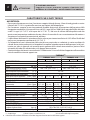
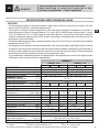
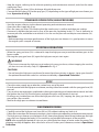
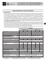
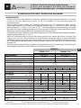
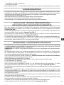
CARATTERISTICHE E DATI TECNICI
AVVERTENZA
• Per erogare la potenza massima, il motore a scoppio richiede almeno 10 ore di rodaggio ad un carico
inferiore del 15÷20 % rispetto alle massime prestazioni dell'idropulitrice.
• Per il motore a scoppio, la massima potenza fornibile diminuisce all’aumentare della quota e della
temperatura ambiente (si ha un calo circa: del 3,5% ogni 305m/1000ft al di sopra del livello del mare
e dell’1% ogni 5,6°C/42°F al di sopra dei 16°C/61°F). Nel caso di utilizzo dell'idropulitrice ad alta
quota o con temperatura ambiente elevata, riferirsi al manuale di uso e manutenzione del motore a
scoppio per le eventuali precauzioni da adottare.
• Le prestazioni dichiarate si intendono riferite ad una pressione atmosferica di 1013 hPa al livello del
mare e con temperatura ambiente di 16°C/61°F.
• Se l‘idropulitrice non è alimentata dalla rete idrica ma aspira da un serbatoio, in certe condizioni la
valvola termostatica può aprirsi ed impedire il completo autoadescamento della pompa. In tali casi,
inserire un tubo in gomma nel raccordo porta gomma della valvola termostatica e portare l’altra
estremità del tubo nel serbatoio da cui la pompa deve aspirare.
• Caratteristiche e dati tecnici sono indicativi. Il Fabbricante si riserva il diritto di apportare alla macchina
tutte le modiche ritenute opportune.
THERMIC
(1)
THERMIC 22 H THERMIC 23 K
5015 4018 3521 5015 4018 3521
MOTORIZZAZIONE
Honda
GX 690 Kohler 12KD477/2
Carburante
Benzina Diesel
Potenza
(kW - HP)
16,4 – 22,0 17,0 – 22,8
Velocità di rotazione nominale - massima
(RPM)
3400 – 3600 [1560 – 1650
(*)
]3400 – 3400 [1500 – 1700
(*)
]
(**)
COLLEGAMENTO IDRAULICO
Massima temperatura acqua di alimentazione
(°C - °F)
60 – 140
Minima temperatura acqua di alimentazione
(°C - °F
)
5 – 41
Minima portata acqua di alimentazione
(l/min - USgpm)
21 – 5,5 23 – 6,1 27 – 7,1 21 – 5,5 23 – 6,1 27 – 7,1
Massima pressione acqua di alimentazione
(bar - psi)
8 – 116
Massima profondità di adescamento
(m - ft)
0 – 0 0 – 0
PRESTAZIONI
Portata massima
(l/min - USgpm)
16,5 – 4,4 18 – 4,8 21 – 5,5 16,5 – 4,4 18 – 4,8 21 – 5,5
Portata nominale
(l/min - USgpm)
15 – 4,0 17,5 – 4,7 20,5 – 5,4 15 – 4,0 17,5 – 4,7 20,5 – 5,4
Pressione massima
(bar - psi)
500 – 7250 400 – 5800 350 – 5075 500 – 7250 400 – 5800 350 – 5075
Pressione nominale
(bar - psi)
480 – 6960 385 – 5580 335 – 4850 480 – 6960 385 – 5580 335 – 4850
Massima forza di reazione sull'idropistola
(N)
78 83 91 78 83 91
Livello di pressione sonora - Incertezza
(dB(A))
89 – 0,7
(3)
89 – 0,7
(2)
89 – 0,7
(3)
89 – 0,7
(2)
Livello di potenza sonora
(dB(A))
107
(3)
107
(2)
107
(3)
107
(2)
Vibrazione mano-braccio operatore - Incertezza
(m/s
2
)
3,9 – 0,24
(3)
3,9 – 0,24
(2)
3,9 – 0,24
(3)
3,9 – 0,24
(2)
OLIO POMPA
15W–40
(4)
15W–40
(4)
OLIO RIDUTTORE
80W–90 –
MASSA E DIMENSIONI
Lunghezza x larghezza x altezza
(mm - in)
1185 x 740 x 1020 - 46,65 x 29,13 x 40,16
Massa
(kg - lb)
180 - 397 235 - 518
(*)
Riduttore R = 1 : 2,18.
(**)
Cinghia Puleggia
(1)
Tutti i modelli sono dotati di avviamento elettrico.
(2)
Misure eseguite in accordo ad EN 60335-2-79.
(3)
Misure eseguite in accordo ad EN 1829-1.
(4)
Si veda anche la tabella degli olii corrispondenti.
Caratteristiche e dati sono indicativi. Il Fabbricante si riserva il diritto di apportare alla macchina tutte le modiche ritenute opportune.
IT
ATTENZIONE
ISTRUZIONI ORIGINALI
Leggere e tener presente quanto riportato nel
MANUALE D’ISTRUZIONE AVVERTENZE DI SICUREZZA.

9
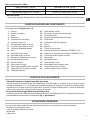
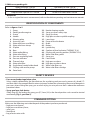
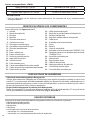
Olii corrispondenti 15W40:
Mobil Delvac MX 15W-40 Total Rubia TIR 7400 15W-40
Shell Rimula R4 15W-40 ENI i-Sigma performance E7 15W-40
Gazprom-Neft super oil GTD 15W-40 Castrol GTX Professional 15W-40
AVVERTENZA
• Per quanto riguarda i lubricanti dei motori, fare riferimento ai relativi manuali di uso e manutenzione.
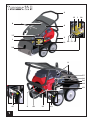
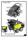
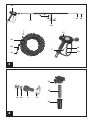
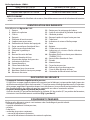
IDENTIFICAZIONE DEI COMPONENTI
Fare riferimento alle gure da 1 a 5.
1 - Pompa
2 - Motore a scoppio
3 - Telaio
4 - Manubrio
8 - Targhetta di avvertenza
9 - Supporto accessori
11 - Portagomma ingresso acqua
12 - Fascetta tubo ingresso acqua
13 - Targhetta di identicazione
14 - Base
15 - Raccordo uscita acqua
16 - Raccordo ingresso acqua
17 - Manopola regolazione pressione
18 - Indicatore di pressione
20 - Valvola termica
23 - Fitro ingresso acqua
24 - Testina portaugello canna semplice
27 - Tappo olio con sato per pompa
28 - Serbatoio benzina
29 - Spillo pulizia ugello
32 - Fermo di sicurezza leva idropistola
33 - Leva Idropistola
34 - Attacco rapido tubo alta pressione
35 - Tubo lancia
38 - Indicatore livello olio pompa
41 - Freno
42 - Batteria
43 - Chiave di accensione
44 - Indicatore livello olio riduttore (THERMIC 22 H)
46 - Tappo olio con sato per riduttore (THERMIC 22 H)
49 - Guarnizione ltro ingresso acqua
57 - Idropistola
58 - Manopola lancia
59 - Tubo alta pressione
60 - Manichetta tubo alta pressione
61 - Coppa ltro ingresso acqua
63 - Cartuccia ltro ingresso acqua
DISPOSITIVI DI SICUREZZA
• Valvola di limitazione/regolazione della pressione.
Valvola, opportunamente tarata dal Fabbricante, che permette di regolare la pressione di lavoro
tramite la manopola (17) e che consente al uido pompato di ritornare all’aspirazione della pompa,
impedendo l’insorgere di pressioni pericolose, quando si chiude l’idropistola o si cerca di impostare
valori di pressione al di sopra di quelli massimi consentiti.
• Dispositivo di bloccaggio della leva dell’idropistola.
Fermo di sicurezza(32) che consente di bloccare la leva(33) dell’idropistola (57) in posizione di chiusura,
prevenendone funzionamenti accidentali (Fig.3, posizione S).
DOTAZIONE STANDARD
Accertarsi che nella confezione del prodotto acquistato siano contenuti i seguenti elementi:
• idropulitrice ad alta pressione;
• tubo di mandata ad alta pressione;
• idropistola;
• tubo lancia;
IT

10
• busta degli accessori contenente:
- manuale di uso e manutenzione;
- manuale di uso e manutenzione del motore a scoppio;
- dichiarazione di conformità;
- kit di aspirazione comprendente: raccordo e fascetta;
- spillo pulizia ugello;
In caso di problemi, rivolgersi al rivenditore o ad un centro di assistenza autorizzato.
ACCESSORI OPZIONALI
È possibile integrare la dotazione standard dell’idropulitrice con la seguente gamma di accessori:
• lancia sabbiante: ideata per levigare superci, eliminando ruggine, vernice, incrostazioni, ecc.;
• sonda spurgatubi: ideata per disotturare tubazioni e condutture;
• lance ed ugelli di vari tipi;
• idrospazzola rotante: ideata per la pulizia di superci delicate;
• ugello rotante: ideato per la rimozione di sporco ostinato;
• lancia schiumogena: ideata per una più ecace distribuzione del detergente.
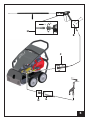
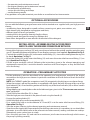
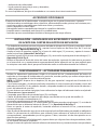
INSTALLAZIONE MONTAGGIO DEGLI ACCESSORI
E RIEMPIMENTO OLIO CARTER MOTORE A SCOPPIO
• Dopo averlo srotolato, avvitare l’estremità del tubo alta pressione (59) (lato senza attacco rapido)
al letto dell’idropistola(57) e serrare a fondo con due chiavi sse da 22 mm(non in dotazione).
OperazioneB di Fig.5.
• Collegare il raccordo ad attacco rapido(34) al raccordo di uscita acqua(15), avvitare e serrare la ghiera
a fondo a mano. Operazione C di Fig.5.
• Inserire la guarnizione(49) nel raccordo ingresso acqua(16) ed avvitarvi il portagomma ingresso acqua(11).
OperazioneD di Fig.5.
• Eettuare il riempimento d'olio del carter del motore a scoppio, rispettando quanto riportato sul
relativo manuale di uso e manutenzione (tale operazione non è da eseguirsi per le macchine dotate
di motore diesel, in quanto il riempimento d'olio è già stato eettuato in fabbrica).
FUNZIONAMENTO ATTIVITÀ PRELIMINARI
• Eseguire le operazioni preliminari riportate nel manuale di uso e manutenzione del motore a scoppio
che equipaggia l'idropulitrice. In particolare rammentare di eettuare il rifornimento di carburante e
la verica del livello dell’olio del motore.
NOTA: la THERMIC dispone di un capiente serbatoio(28) integrato nel telaio dell’idropulitrice.
• Vericare, a motore spento ed a macchina completamente rareddata, il livello dell'olio della pompa
tramite l'indicatore di livello(38). Nei modelli che ne sono provvisti, vericare anche il livello dell'olio
del riduttore, tramite l'indicatore di livello(44).
Per eventuali rabbocchi, fare riferimento ai tipi di lubricante riportati nel paragrafo
“CARATTERISTICHE
E DATI TECNICI”.
• Vericare che il ltro ingresso acqua(23) sia pulito.
• Portare l’idropulitrice nella postazione di lavoro, movimentandola sfruttando il manubrio(4).
• Azionare il freno di stazionamento(41).
• Srotolare completamente il tubo alta pressione(59).
• Sfruttando la fascetta (12) in dotazione, ssare al portagomma ingresso acqua (11) un tubo di
alimentazione avente diametro interno di 19 mm/0,75 in. Operazione G di Fig.5.
• Mettere in moto il motore a scoppio, facendo riferimento al relativo manuale di uso e manutenzione.
• Aprire il rubinetto di alimentazione acqua (in caso di collegamento alla rete idrica dell’acqua potabile è

11
obbligatorio utilizzare un disconnettore idrico: per il suo utilizzo riferirsi al relativo manuale d’istruzione),
vericando che non vi siano gocciolamenti. Oppure introdurre il tubo di aspirazione in un serbatoio
di pescaggio.
• Premere la leva(33) dell’idropistola ed attendere che fuoriesca un getto d’acqua continuo, indice di
un corretto adescamento della pompa.
• Arrestare il motore a scoppio, facendo riferimento al relativo manuale di uso e manutenzione e chiudere
l’eventuale rubinetto di alimentazione acqua.
• Premere la leva(33) dell’idropistola per scaricare l'eventuale pressione residua.
• Collegare all'idropistola(57) il tubo lancia(35). Operazione H di Fig.5.
FUNZIONAMENTO STANDARD AD ALTA PRESSIONE
• Riavviare il motore a scoppio, facendo riferimento al relativo manuale di uso e manutenzione.
• Aprire l’eventuale rubinetto di alimentazione acqua.
• Premere la leva(33) dell'idropistola, vericando che lo spruzzo dell’ugello sia uniforme e che non vi
siano gocciolamenti.
• Regolare, se necessario, la pressione agendo sulla manopola regolazione pressione(17). Ruotare la
manopola in senso orario per aumentare la pressione; ruotare la manopola in senso antiorario per
diminuire la pressione. Il valore della pressione è visibile sull'indicatore di pressione(18).
AVVERTENZA
• Prima di richiedere le massime prestazioni all'idropulitrice è buona norma far scaldare il motore per
un paio di minuti.
INTERRUZIONE DEL FUNZIONAMENTO
• Rilasciando la leva(33) dell’idropistola, si interrompe l’erogazione del getto ad alta pressione e
l’idropulitrice passa al funzionamento in by-pass.
• Ripremendo la leva(33) dell’idropistola, riprende l’erogazione del getto ad alta pressione.
ATTENZIONE
• Qualora si debba interrompere l’erogazione del getto ad alta pressione ed appoggiare l’idropistola, senza
arrestare la macchina, occorre inserire il fermo di sicurezza(32). Operazione S di Fig.6.
AVVERTENZA
• Non lasciare l'idropulitrice per più di tre minuti in by-pass (idropistola chiusa) se non è stata fatta
installare da un Tecnico Specializzato la valvola termostatica opzionale.
ARRESTO
• Chiudere il rubinetto di alimentazione acqua, oppure estrarre il tubo di aspirazione dal serbatoio di
pescaggio.
• Svuotare dall’acqua l’idropulitrice facendola funzionare per alcuni secondi con la leva(33) dell’idropistola
premuta.
• Eseguire le operazioni relative all’arresto riportate nel manuale di uso e manutenzione del motore a
scoppio e slare la chiave di accensione(43).
• Eliminare l’eventuale pressione residua rimasta nel tubo alta pressione(59), tenendo premuta per
alcuni secondi la leva(33) dell’idropistola.
• Attendere che l’idropulitrice si sia rareddata.
IT

12
MESSA A RIPOSO
• Riavvolgere il tubo alta pressione(59) con cura, evitando piegature.
• Eseguire le operazioni relative alla messa a riposo riportate nel manuale di uso e manutenzione del
motore a scoppio.
• Riporre con cura l'idropulitrice in un luogo asciutto e pulito, facendo attenzione a non danneggiare il
tubo alta pressione. Azionare il freno(41) per evitare movimenti incontrollati della macchina.
NOTA: dopo una sosta prolungata è possibile che si verichi un leggero gocciolamento d'acqua sotto la
pompa. Tale gocciolamento, di norma, scompare dopo alcune ore di funzionamento. Qualora persista,
rivolgersi ad un Tecnico Specializzato.
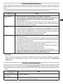
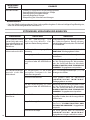
MANUTENZIONE ORDINARIA
Eseguire le operazioni descritte nel paragrafo
"ARRESTO"
ed attenersi a quanto riportato nella tabella
seguente.
Ricordare anche di eseguire le operazioni relative alla manutenzione ordinaria riportate nel manuale
di uso e manutenzione del motore a scoppio, con particolare riguardo al controllo dell'olio motore, del
ltro aria e della candela.
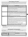
INTERVALLO DI
MANUTENZIONE INTERVENTO
Ad ogni uso • Controllo tubo alta pressione, raccordi, idropistola, tubo lancia.
Qualora uno o più particolari risultassero danneggiati, non utilizzare
assolutamente l’idropulitrice e rivolgersi ad un Tecnico Specializzato.
• Controllo livello dell'olio della pompa.
• Rimuovere sul motore a scoppio sporcizia e detriti dalle alette di rareddamento,
dagli schermi di ingresso aria, dai meccanismi e dalle molle del regolatore di giri
(fare riferimento al manule di uso e manutenzione del motore a scoppio).
Settimanalmente • Pulizia ltro ingresso acqua(23).
Svitare il tappo(61) ed estrarre la cartuccia(63), (si veda la Fig.4). Per la pulizia, in
genere è suciente passare la cartuccia sotto un getto d’acqua corrente, o soarla
con aria compressa. Nei casi più dicili, usare un prodotto anticalcare o sostituirla,
rivolgendosi per l’acquisto del ricambio ad un centro di assistenza autorizzato.
Rimontare la cartuccia e serrare a fondo il tappo.
Mensilmente • Pulizia ltro ingresso acqua(23) (si faccia riferimento a quanto detto sopra).
• Pulizia ugello.
Per la pulizia, in genere è suciente passare entro il foro dell’ugello lo spillo(29)
in dotazione. Qualora non si ottengano risultati apprezzabili, sostituire l'ugello,
rivolgendosi per l'acquisto del ricambio ad un centro di assistenza autorizzato.
L'ugello professionale a ventaglio sso che equipaggia le testine portaugello(24)
è sostituibile sfruttando una chiave a tubo da 14 mm (non in dotazione).
• Oliare od ingrassare le parti in rotazione o scorrimento accessibili all'operatore (si
faccia anche riferimento al manuale di uso e manutenzione del motore a scoppio).
• Verica integrità circuiti di ingresso ed uscita acqua.
• Verica ssaggio pompa al motore e motore al telaio.
Qualora i fissaggi risultassero precari, non utilizzare assolutamente
l'idropulitrice e rivolgersi ad un Tecnico Specializzato.
AVVERTENZA
• Durante il funzionamento, l’idropulitrice non deve essere troppo rumorosa e sotto di essa non vi
devono essere evidenti gocciolamenti di acqua o di olio. Qualora ciò dovesse accadere, fare controllare
la macchina da un Tecnico Specializzato.

13
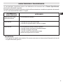
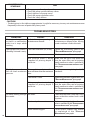
MANUTENZIONE STRAORDINARIA
La manutenzione straordinaria deve essere eettuata esclusivamente da un Tecnico Specializzato,
attenendosi alla tabella seguente.
Ricordare anche di eseguire le operazioni relative alla manutenzione straordinaria riportate nel manuale
di uso e manutenzione del motore a scoppio.
INTERVALLO DI
MANUTENZIONE INTERVENTO
Dopo le prime 50ore
difunzionamento
• Sostituzione olio pompa.
Ogni 200 ore • Controllo circuito idraulico pompa.
• Controllo ssaggio pompa e motore a scoppio.
Ogni 500 ore • Sostituzione olio pompa ed olio riduttore.
• Controllo valvole aspirazione/mandata pompa.
• Controllo serraggio viti pompa.
• Controllo valvola di regolazione pompa.
• Verica dei dispositivi di sicurezza.
AVVERTENZA
• I dati riportati in tabella sono indicativi. Possono essere necessari interventi più frequenti nel caso di
uso particolarmente gravoso.
IT

14
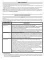
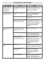
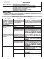
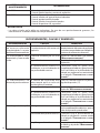
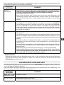
INCONVENIENTI, CAUSE E RIMEDI
INCONVENIENTI CAUSE RIMEDI
Il motore a scoppio
non parte o presenta
irregolarità o si
arresta durante il
funzionamento.
Fare riferimento al manuale di
uso e manutenzione del motore
a scoppio.
Fare riferimento al manuale di uso e
manutenzione del motore a scoppio
dopo aver vericato che vi sia
carburante nel serbatoio.
L’idropulitrice vibra
molto ed è rumorosa.
Il ltro ingresso acqua(23) è
sporco.
Attenersi a quanto riportato nel
paragrafo
“MANUTENZIONE
ORDINARIA”
.
Aspirazione d’aria. Controllare l’integrità del circuito
d’aspirazione.
L’alimentazione idrica è
insuciente o si sta adescando
da una profondità eccessiva.
Vericare che il rubinetto sia
completamente aperto e che la
portata della rete idrica o la profondità
di adescamento siano conformi
a quanto riportato nel paragrafo
“CARATTERISTICHE E DATI
TECNICI”.
L'idropulitrice non
raggiunge la massima
pressione.
La valvola di regolazione è
impostata per un valore di
pressione inferiore a quello
massimo.
Ruotare in senso orario la manopola
regolazione pressione(17).
L’ugello è usurato. Sostituire l’ugello secondo
quanto riportato nel paragrafo
“MANUTENZIONE ORDINARIA”
.
L’alimentazione idrica è
insuciente o si sta adescando
da una profondità eccessiva.
Vericare che il rubinetto sia
completamente aperto e che la
portata della rete idrica o la profondità
di adescamento siano conformi
a quanto riportato nel paragrafo
“CARATTERISTICHE E DATI
TECNICI”.
Dall’ugello non esce
acqua.
Manca l’acqua. Vericare che il rubinetto della rete
idrica sia completamente aperto o che
il tubo di aspirazione possa adescare.
Eccessiva profondità
d’aspirazione
Vericare che la profondità di
adescamento sia conforme a
quanto riportato nel paragrafo
“CARATTERISTICHE E DATI
TECNICI”
.
Ugello acqua otturato. Pulire e/o sostituire l’ugello secondo
quanto riportato nel paragrafo
“MANUTENZIONE ORDINARIA”
.

15
SPECIFICATIONS AND TECHNICAL DATA
CAUTION
• For the engine to reach its maximum power it needs at least 10 hours running-in at a load 15 to 20%
lower than the machine’s maximum performance.
• The engine’s maximum power diminishes as the altitude and ambient temperature at which it is
working increases (there is a drop of about: 3.5% every 305 m/1000 ft above sea level and 1% every
5.6°C/42°F above 16°C/61°F). If the high pressure water cleaner is used at a high altitude or with high
ambient temperature please refer to the engine’s operating and maintenance manual to see if any
precautions need to be taken.
• The declared performance refers to an atmospheric pressure of 1013 hPa at sea level and an ambient
temperature of 16°C/61°F.
• If the high pressure cleaner is not connected to the water mains but takes water from a tank, in certain
conditions the thermostat valve can open and prevent the complete self-priming of the pump. In
these cases, t a rubber hose into the hose connection of the thermostatic valve and bring the other
end of the hose to the tank from where the pump takes the water.
• The specications and technical data are approximate. The manufacturer reserves the right to make
all changes to the machine it deems appropriate.
THERMIC
(1)
THERMIC 22 H THERMIC 23 K
5015 4018 3521 5015 4018 3521
MOTORISATION
Honda
GX 690 Kohler 12KD477/2
Fuel
Petrol Diesel fuel
Power
(kW - HP)
16,4 – 22,0 17,0 – 22,8
Nominal rotation speed - maximum
(RPM)
3400 – 3600 [1560 – 1650
(*)
]3400 – 3400 [1500 – 1700
(*)
]
(**)
HYDRAULIC CIRCUIT
Maximum supply water temperature
(°C - °F)
60 – 140
Minimum supply water temperature
(°C - °F)
5 – 41
Minimum supply water ow rate
(l/min - USgpm)
21 – 5,5 23 – 6,1 27 – 7,1 21 – 5,5 23 – 6,1 27 – 7,1
Maximum supply water pressure
(bar - psi)
8 – 116
Maximum priming depth
(m - ft)
0 – 0 0 – 0
PERFORMANCE
Maximum ow rate
(l/min - USgpm)
16,5 – 4,4 18 – 4,8 21 – 5,5 16,5 – 4,4 18 – 4,8 21 – 5,5
Nominal ow rate
(l/min - USgpm)
15 – 4,0 17,5 – 4,7 20,5 – 5,4 15 – 4,0 17,5 – 4,7 20,5 – 5,4
Maximum pressure
(bar - psi)
500 – 7250 400 – 5800 350 – 5075 500 – 7250 400 – 5800 350 – 5075
Nominal pressure
(bar - psi)
480 – 6960 385 – 5580 335 – 4850 480 – 6960 385 – 5580 335 – 4850
Maximum reaction force on the spray gun
(N)
78 83 91 78 83 91
Sound pressure level - Uncertainty
(dB(A))
89 – 0,7
(3)
89 – 0,7
(2)
89 – 0,7
(3)
89 – 0,7
(2)
Sound power level
(dB(A))
107
(3)
107
(2)
107
(3)
107
(2)
Operator hand-arm vibration - Uncertainty
(m/s
2
)
3,9 – 0,24
(3)
3,9 – 0,24
(2)
3,9 – 0,24
(3)
3,9 – 0,24
(2)
PUMP OIL
15W–40
(4)
15W–40
(4)
GEARBOX OIL
80W–90 –
WEIGHT AND DIMENSIONS
Length x width x height (mm - in)
(mm - in)
1185 x 740 x 1020 - 46,65 x 29,13 x 40,16
Weight
(kg - lb)
180 - 397 235 - 518
(*)
Gearbox R = 1 : 2,18.
(**) Pulley Belt
(1)
All models have electrical start-up.
(2)
Measurements in agreement with EN 60335-2-79.
(3)
Measurements in agreement with EN 1829-1.
(4)
Also see the corresponding oils table.
The specications and technical data are approximate. The Manufacturer reserves the right to make all changes to the machine it deems appropriate.
EN
WARNING
TRANSLATION OF THE ORIGINAL INSTRUCTIONS
Read and keep in mind that indicated in the
INSTRUCTION MANUAL SAFETY WARNINGS.
EN

16
15W40 corresponding oils:
Mobil Delvac MX 15W-40 Total Rubia TIR 7400 15W-40
Shell Rimula R4 15W-40 ENI i-Sigma performance E7 15W-40
Gazprom-Neft super oil GTD 15W-40 Castrol GTX Professional 15W-40
WARNING
• As far as engine lubricants are concerned, refer to the relative operating and maintenance manuals.
IDENTIFICATION OF COMPONENTS
Refer to gures 1 to 5.
1 - Pump
2 - Petrol/gasoline engines
3 - Frame
4 - Handle
8 - Warning plate
9 - Accessory rack
11 - Water inlet hose-end tting
12 - Water inlet hose clamp
13 - ID plate
14 - Base
15 - Water outlet tting
16 - Water inlet tting
17 - Pressure regulating knob
18 - Pressure indicator
20 - Thermal valve
23 - Water inlet lter
24 - Single barrel nozzle holder head
27 - Oil plug with vent for pump
28 - Petrol tank
29 - Nozzle cleaning needle
32 - Spray gun lever safety stop
33 - Spray gun lever
34 - High pressure hose quickt coupling
35 - Lance hose
38 - Pump oil level indicator
41 - Brake
42 - Battery
43 - Ignition key
44 - Gearbox oil level indicator (THERMIC 22 H)
46 - Oil plug with vent for gearbox (THERMIC 22 H)
49 - Water inlet lter gasket
57 - Spray gun
58 - Lance knob
59 - High pressure hose
60 - High pressure hose sleeve
61 - Water inlet lter cup
63 - Water inlet lter cartridge
SAFETY DEVICES
• Pressure unloader/regulation valve
Valve, suitably calibrated by the Manufacturer, for regulating work pressure by means of a knob (17)
and that allows the pumped uid to return to pump suction thus preventing the onset of dangerous
pressures when closing the spray gun or when trying to set a pressure that is above the maximum
permitted values.
• Spray gun lever lock device.
Safety stop (32) for locking the spray gun (57) lever(33) in the closed position so it cannot be started
accidentally (Fig. 3, position S).
STANDARD FITTING
Make sure the following are inside the pack of the product you have purchased:
• high pressure cleaner;
• high pressure delivery hose;
• spray gun;
• lance hose;
• bag of accessories with:

17
- the operating and maintenance manual;
- the engine operating and maintenance manual;
- the declaration of conformity;
- suction kit with: tting and clamp
- nozzle cleaning needle;
If any problems arise please contact your dealer or an authorised assistance centre.
OPTIONAL ACCESSORIES
You can add the following range of accessories to the standard ones supplied with your high pressure
cleaner:
• sandblasting lance: designed to smooth surfaces, removing rust, paint, encrustations, etc.;
• drain cleaning kit: designed to unclog pipes and ducts;
• dierent types of lances and nozzles;
• rotating brush: designed for cleaning fragile surfaces;
• rotating nozzle: designed for removing stubborn dirt;
• foam lance: designed for a more ecient distribution of the detergent.
INSTALLATION ASSEMBLING THE ACCESSORIES
AND FILLING THEENGINE CRANKCASE WITH OIL
• Unwind the high pressure hose (59) and screw the end without the quickt coupling onto the spray
gun(57) thread and tighten well with two 22 mm xed jaw spanners (not supplied). OperationB in Fig.5.
• Connect the quickt coupling(34) to the water outlet tting(15), screw down and tighten the ring nut
by hand. OperationC in Fig.5.
• Insert the gasket(49) in the water inlet tting (16) and screw the water inlet hose-end tting (11) on
to it. OperationD in Fig.5.
• Fill the engine crankcase with oil, following the instructions given in the relevant operating and
maintenance manual (this is not to be done on machines with Diesel engines as they are lled with
oil in the factory).
OPERATION PRELIMINARY ACTIVITIES
• Do the preliminary activities described in the operating and maintenance manual of the engine
mounted on the high pressure cleaner. In particular remember to ll with fuel and check the level of
engine oil.
NOTE: the THERMIC model has a capacious tank(28) integrated in the high pressure cleaner frame.
• When the engine is o and the machine is completely cold, check the level of pump oil by way of the
level indicator(38). Also check the gearbox oil level by way of the level indicator (44) on those models
thus equipped.
When topping up is needed please refer to the lubricant types given in the
“SpecIFIcatIonS and technIcal
data”
paragraph.
• Check if the water inlet lter (23) is clean.
• Take the high pressure cleaner to the place of work using the handle(4).
• Engage the parking brake(41).
• Unwind the high pressure hose completely(59).
• Fix a supply hose with an inside diameter of 19mm/0,75in to the water inlet hose-end tting (23).
Operation G in Fig.5.
• Start the engine, referring to the relevant operating and maintenance manual.
• Open the water supply tap (if connected to the drinking water mains it is mandatory to use a back-ow
preventer: to use this device refer to the relevant instruction manual), making sure there are no drips.
Alternatively, put a suction hose in a tank.
• Press the spray gun lever(33) and wait for a continuous jet of water to come through which means
the pump is priming correctly.
EN

18
• Stop the engine, referring to the relevant operating and maintenance manual, and close the water
supply tap, if any.
• Press the spray gun lever(33) to discharge all residual pressure.
• Connect the lance hose(35) to the spray gun (57) depending on the type of high pressure cleaner you
have. OperationH in Fig.5.
STANDARD OPERATION HIGH PRESSURE
• Start the engine, referring to the relevant operating and maintenance manual.
• Open the water supply tap, if any.
• Press the spray gun lever(33) checking that the nozzle spray is uniform and there are no drips.
• If necessary regulate the pressure by way of the pressure regulating knob(17). Turn it clockwise to
increase pressure, anticlockwise to reduce it. You can see the pressure on the pressure indicator(18).
CAUTION
• Before expecting maximum performance of the high pressure cleaner it is good practice to warm
the engine up for a couple of minutes.
STOPPING OPERATION
• When the spray gun lever(33) is released it stops the high pressure jet and the machine goes to the
bypass mode.
• Pressing the spray gun lever(33) again the high pressure jet starts again.
WARNING
• If you have to interrupt the high pressure jet and put the spray gun down, without stopping the machine,
you have to insert the safety stop(32). Operation S in Fig.3.
CAUTION
• Do not leave the high pressure cleaner for more than three minutes in bypass (spray gun closed) if
the optional thermostatic valve has not been installed by a Specialized Technician.
STOP
• Close the water supply tap or take the suction hose out of the tank.
• Drain the water from the high pressure cleaner, working it for a few seconds with the spray gun lever(33)
pressed.
• Carry out the stop operations, explained in the engine operating and maintenance manual and take
the ignition key out(43) (Diesel engines and petrol engines with electrical start-up).
• Discharge any residual pressure from the high pressure hose(59), keeping the spray gun lever(33)
pressed for a few seconds.
• Wait for the high pressure cleaner to cool down.
DECOMMISSIONING
• Carefully rewind the high pressure hose(30) or (59) without making any kinks in it.
• Follow the instructions for decommissioning as given in the engine operating and maintenance manual.
• The high pressure cleaner must be kept in a dry, clean place paying attention not to damage the high
pressure hose. Engage the brake (41) to avoid any uncontrolled movements of the machine.
NOTE: after a prolonged period of non-use you could nd a few drops of water under the pump. This
dripping normally disappears after a few hours of use. If it does persist however, contact a Specialized
Technician.

19
ROUTINE MAINTENANCE
Do the operations described in the
“Stop”
paragraph and follow the instructions given in the following
table.
Also remember to carry out the routine maintenance jobs given in the engine operating and maintenance
manual, especially as regards to checking engine oil, the air lter and the spark plug.
MAINTENANCE
SCHEDULE JOB
Every time it is
used
• Check the high pressure hose, ttings, spray gun and lance hose.
If one or more parts are found to be damaged do not, under any circumstances,
use the high pressure cleaner and contact a Specialized Technician.
• Check pump oil level.
• Remove all dirt and debris from the cooling ns on the engine, from the air
inlet grids, from the mechanisms and rev regulator springs (refer to the engine
operating and maintenance manual).
Weekly • Clean the water inlet lter(23).
Unscrew the cap(61) and take the cartridge out(63), (see Fig.4). It is normally
enough to put the cartridge under running water or blow it with compressed air
to clean it. In the most dicult cases, use a scale remover or replace it, contacting
an authorised assistance centre to buy the new cartridge.
Mount the cartridge and screw the plug back down.
Monthly • Clean the water inlet lter(23) (refer to what has been explained previously).
• Clean the nozzle.
It is normally enough to put the needle (29) supplied through the hole of the
nozzle to clean it. If the results are not good, replace the nozzle purchasing it from
an authorised assistance centre.
The professional xed fan nozzle mounted on the nozzle holder heads (24) can
be replaced using a 14 mm box spanner (not supplied).
• Oil or grease the rotating or sliding parts the operator is able to reach (refer also
to the engine operating and maintenance manual).
• Check soundness of the water inlet and outlet circuits.
• Check clamping of the pump to the engine and the engine to the frame.
If clamping is found to be insecure do not, under any circumstances, use the
high pressure cleaner and contact a Specialized Technician.
CAUTION
• When working, the high pressure cleaner should not be too noisy and there should be no obvious
drips of water or oil underneath it. If this is the case have the machine checked by a Specialized
Technician.
SPECIAL MAINTENANCE
Special maintenance must only be done by a Specialized Technician, complying with the following table.
Also remember to carry out the special maintenance jobs listed in the engine operating and maintenance
manual.
MAINTENANCE
SCHEDULE JOB
After the rst 50hours of
operation
• Change pump oil.
Every 200 hours • Check the pump’s hydraulic circuit.
• Check pump and engine clamping.
(continues on the next page)
EN

20
MAINTENANCE
SCHEDULE JOB
Every 500 hours • Change pump oil and gearbox oil.
• Check the pump suction/delivery valves.
• Check tightness of pump screws.
• Check the pump regulation valve.
• Check the safety devices.
CAUTION
• The data given in the table are approximate. It might be necessary to carry out maintenance more
frequently in the case of particularly heavy work.
TROUBLESHOOTING
PROBLEMS CAUSES REMEDIES
The engine does not start
or there is a malfunction
with it or it stops while
working.
Refer to the engine operating and
maintenance manual.
Refer to the engine operating and
maintenance manual after having
made sure there is fuel in the tank.
The high pressure cleaner is
vibrating a lot and is noisy.
The water inlet lter(23) is dirty. Follow the instructions given in the
“routIne MaIntenance”
paragraph.
Air suction. Check soundness of the suction circuit.
Not enough water is being
supplied or priming depth is
excessive.
Make sure the tap is fully open and
that the mains ow rate or priming
depth conform to what is specied in
the
“SpecIFIcatIonS and technIcal data”
paragraph.
The high pressure cleaner
fails to reach maximum
pressure.
The regulation valve is set for a
pressure lower than the maximum
one.
Turn the pressure regulating knob (17)
clockwise.
The nozzle is worn. Replace the nozzle as explained in the
“routIne MaIntenance”
paragraph.
Not enough water is being
supplied or priming depth is
excessive.
Make sure the tap is fully open and
that the mains ow rate or priming
depth conform to what is specied in
the
“SpecIFIcatIonS and technIcal data”
paragraph.
No water coming through
the nozzle.
No water. Check that the mains water tap is fully
open or that the suction hose is able
to prime.
Suction depth is excessive Make sure priming depth conforms to
what is specied in the
“SpecIFIcatIonS
and technIcal data”
paragraph.
Water nozzle clogged. Clean and/or replace the nozzle
as explained in the
“ro u t I n e
MaIntenance”
paragraph.
La pagina si sta caricando...
La pagina si sta caricando...
La pagina si sta caricando...
La pagina si sta caricando...
La pagina si sta caricando...
La pagina si sta caricando...
La pagina si sta caricando...
La pagina si sta caricando...
La pagina si sta caricando...
La pagina si sta caricando...
La pagina si sta caricando...
La pagina si sta caricando...
La pagina si sta caricando...
La pagina si sta caricando...
La pagina si sta caricando...
La pagina si sta caricando...
La pagina si sta caricando...
La pagina si sta caricando...
La pagina si sta caricando...
La pagina si sta caricando...
-
 1
1
-
 2
2
-
 3
3
-
 4
4
-
 5
5
-
 6
6
-
 7
7
-
 8
8
-
 9
9
-
 10
10
-
 11
11
-
 12
12
-
 13
13
-
 14
14
-
 15
15
-
 16
16
-
 17
17
-
 18
18
-
 19
19
-
 20
20
-
 21
21
-
 22
22
-
 23
23
-
 24
24
-
 25
25
-
 26
26
-
 27
27
-
 28
28
-
 29
29
-
 30
30
-
 31
31
-
 32
32
-
 33
33
-
 34
34
-
 35
35
-
 36
36
-
 37
37
-
 38
38
-
 39
39
-
 40
40


Lavor THERMIC 18 BS Manuale utente
- Categoria
- Idropulitrici
- Tipo
- Manuale utente
- Questo manuale è adatto anche per
in altre lingue
- français: Lavor THERMIC 18 BS Manuel utilisateur
- español: Lavor THERMIC 18 BS Manual de usuario
- Deutsch: Lavor THERMIC 18 BS Benutzerhandbuch
Documenti correlati
Altri documenti
-
Efco IPX 2000 S Manuale del proprietario
-
Comet K Xtreme Manuale utente
-
-
-
Efco PW 250 HC Manuale del proprietario
-
Comet KP Serie Manuale utente
-
-
-