FA00496M4A - ver. 2 - 06/2017
General Precautions
Important people-safety instructions: READ CAREFULLY! • Installing,
programming, commissioning and maintenance must only be done by
qualified, expert sta and in full compliance with the applicable law. •
Wear anti-static footwear and clothing when working on the control board.
• Keep these precautions. • Always cut o the mains power supply before
performing any maintenance or cleaning. • This product should only be
used for the purpose for which it was explicitly designed. Any other use
is dangerous. • The manufacturer cannot be held liable for any damage
resulting from wrongful, improper and unreasonable use.
Description
Double-technology volumetric detector with one MW microwave
section and one PIR passive infrared section. The main characteristics
are: anti-masking function on the microwave with dedicated output,
anti-blinding function on the infrared (AB) and option to switch o the
microwave (ECO).
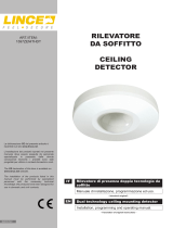
Description of parts A
1 Swivel
2 Swivel screw
3 Plastic base
4 Tab
5 Base opening slit
F Board
Technical data
Type PXDTAM01
Power supply (V DC) 9 to 15
Maximum absorption when in alarm memory (mA) 34
Absorption when idle (mA) 20
Microwave frequency (Ghz) 10.525
Microwave power (dBm) 8
Alarm time (s) 3
Alarm-contact range at 24 V (mA) 100
Tamper-contact range at 30 V (mA) 100
Anti-masking contact range at 48 V (mA) 300
theoretic MTBF (h) 120,000
Installing height (m) 2.1 to 2.3
Range (m) 15
Coverage arc (°) 90
Number of beams across four levels (n) 18
Dimensions (mm) 107x61.5x43
Operating temperature (°C) -10 to +55
Regulatory compliance: EN50131-2-4 GRADE 2, CLASS II
Guide to installing
Install the sensor while considering the characteristics of the room you
are going to protect so as to install it in the most eective position to
provide maximum coverage. Corner fitting is always best. Position the
sensor facing into the room, away from any doors, windows, moving
machinery and heat sources. Keep it turned away from any sun-expo-
sed window panes.
Fitting
Remove the plastic shell by using a screwdriver to lightly press and
separate it E from the base. Remove the circuit board by F by ben-
ding one of the tabs 4.
TO WALL/IN CORNER
To corner fit the device, drill the marked areas A1 and A2 and to
wall fit the device, do the same to the P1 or P2 marked areas B.
Drill one of the holes in the (PC) Cable gland on the bottom of the
plastic base B. Drill 6 mm fastening holes into the wall, and run the
cable through the chosen cable gland. Fasten the base to the wall
by using the supplied screws and dowels. These must not touch the
control board. Refit the circuit board onto the plastic base.
ON SWIVEL
Run the cable through part 7 and fasten it to the wall or ceiling using
the supplied screws, while keeping the locking tab I on the left. Fit
part H to part 7 and turn it all the way in one direction, depending
on how you have fitted the device to the wall K, E or ceiling J, F.
Completely perforate the FS 'swivel fastening' parts and the PCS 'swi-
vel cable-gland' parts C and fasten the base to the swivel while kee-
ping the cable downwards. Turn the plastic base to the right direction
and lock it by tightening the screw. Refit the circuit board.
Terminal board Q
IINPUT: input for detecting whether the system is armed or
not
+ -/12 V Input for 12 V power supply
NC/TAMP NC tamper contact
NC/ALL NC alarm relay
NC/MASK NC Anti-masking relay
Powering on
Connect the sensor to the control unit, the LEDs will flash in alternating
mode for 60 seconds. Conduct a Walk Test at the end.
WalkTest
Microwave test
Set Dip-switch 2 to OFF, adjust potentiometer P to minimum (range
0.5 m - 15 m), move about the area to protect and check that the
green MW LED L lights up at each walk about.
NOTE. The microwave range should be set to minimum to prevent
disturbances beyond the area being protected (for example outside of
the room being protected).
PIR Test
Fit the sensor's front panel and, with the LEDs o, move about the
area it is meant to protect and verify whether the PIR is detecting by
checking the yellow LED N.
Dipswitch O
ON
MASK: enabling the ANTI-MASK function
The LEDs will flash for about 60 seconds, the sensor will
calibrate the Anti-masking according to the characteristics
of the room and objects within. Close the plastic front-panel
and move away from the sensor. During this phase, no moving
object must be in the immediate vicinity of the sensor so as not
to oset the calibration. Once finished, the sensor will be ready
to operate. It is best to enable the Anti-masking after the other
installation procedures are done.
When the sensor is masked, the three LEDs will flash until the
cause which generated this has been removed.
OFF
AB: AND detection mode
An alarm condition is manifested when both the MW and the
PIR sections, almost simultaneously, show an intrusion alert.
Such configuration is best for installations that could have en-
vironmental instability.
ON
AB: AB (anti-blinding) detection mode
An alarm condition is manifested when more than one MW
detection takes place with no PIR detection. Such configuration
is best for installations that require the AND mode, which could
have blind-spots for the PIR, or for places where paper or
spray sabotage on the PIR lens is likely.
ON
SENS: Sensitivity reduction
PIR: Detection with two beams instead of one.
MW: the detection speed goes from 0.25 to 0.5 seconds with
a movement of 0.6 m/s.
ON LED: LED OFF. The memory viewings remain active.
H Detection diagram
Functions with input line
This set of functions are activated/deactivated by arming or disarming
the system.
Consider
12 V on the INPUT = system disarmed
0 V or open on the INPUT = system disarmed.
Remote LED enabling (condition required - LED OFF)
When the system is disarmed, the sensor sets up to restore the de-
tection viewings. The viewings will be restored to the first actual de-
tection, and remain active for 30 seconds.
Microwave's eco-switching-o function (conditions required;
LED OFF; anti-masking disabled)
Once 30 seconds, for restoring the viewings, have elapsed (see RE-
MOTE LED ENABLING), from the switching o of the LEDs, also the
Microwave emissions will be disabled so as not to needlessly radiate
the room that is being protected. The Microwave will be restored once
the system is armed again.
Memories
Once the system is armed, it will display the memory of the first de-
tected alarm, as shown in the table below. The memory will be reset
when the system is armed once again.
Memory delay for using in timer zones
Exiting time: Any alarms that sound within the first 30 seconds after
arming the system, will be deleted.
Entering time: any alarms that sound within the first 30 seconds of
disarming the system, will be deleted.
Viewing in memory state
ALARM GREEN LED RED LED YELLOW LED
PIR+MW OFF ON OFF
PIR OFF ON ON
MW ON ON OFF
ANTI-MASKING LAMP ON LAMP
This product complies with the law.
Decommissioning and disposal. Dispose of the packaging and the
device at the end of its life cycle, responsibly, in compliance with the
laws in force in the country where the product is used. The recyclable
components are marked with a symbol and the material's ID marker.
THE DATA PRESENTED IN THIS MANUAL MAY BE CHANGED, AT ANY
TIME, AND WITHOUT NOTICE. MEASUREMENTS, UNLESS OTHERWISE
STATED, ARE IN MILLIMETERS.
ENGLISH
Instructions générales
Instructions importantes pour la sécurité des personnes : À LIRE AT-
TENTIVEMENT ! • L’installation, la programmation, la mise en service et
l'entretien doivent être eectués par du personnel qualifié et dans le plein
respect des normes en vigueur. • Porter des vêtements et des chaussures
antistatiques avant d'intervenir sur la carte électronique. • Conserver ces
instructions. • Toujours couper le courant électrique durant les opérations
de nettoyage ou d'entretien. • Ce produit ne devra être destiné qu'à l'uti-
lisation pour laquelle il a été expressément conçu. Toute autre utilisation
est à considérer comme dangereuse. • Le fabricant ne peut toutefois
être tenu pour responsable des éventuels dommages qui naîtraient d'une
utilisation erronée ou déraisonnable.
Description
Détecteur volumétrique bi-technologie avec une section à micro-onde
(MW) et une section à infrarouge passif (PIR). Caractéristiques prin-
cipales : fonction anti-masque sur la micro-onde avec sortie dédiée,
fonction anti-éblouissement sur l’infrarouge (AB) et possibilité d’ex-
tinction de la micro-onde (ECO).
Description des parties A
1 Rotule
2 Vis de la rotule
3 Fond plastique
4 Patte
5 Fente d’ouverture du fond
F Carte
Données techniques
Type PXDTAM01
Alimentation (VDC) 9 - 15
Absorption max. en mémoire d'alarme (mA) 34
Absorption au repos (mA) 20
Fréquence micro-onde (Ghz) 10,525
Puissance micro-onde (dBm) 8
Temps d'alarme (s) 3
Portée contact d'alarme à 24 V (mA) 100
Portée contact autoprotection à 30 V (mA) 100
Portée contact anti-masque à 48 V (mA) 300
MTBF théorique (h) 120,000
Hauteur d'installation (m) 2,1 - 2,3
Portée (m) 15
Couverture (°) 90
Nombre de faisceaux sur 4 plans (n) 18
Dimensions (mm) 107x61,5x43
Température de fonctionnement (°C) de -10 à +55
Conformité norme : EN50131-2-4 GRADE 2, CLASSE II
Guide d’installation
Analyser les caractéristiques de la pièce à protéger de manière à
identifier la position du capteur permettant une couverture maximale.
Toujours préférer une installation en angle. Positionner le capteur vers
l’intérieur de la pièce, à l’écart de portes, fenêtres, machines en mou-
vement et sources de chaleur, et ne pas le diriger vers des surfaces
vitrées exposées au soleil.
Fixation
Enlever la base en plastique à l’aide d’un tournevis et appuyer légè-
rement E pour la décrocher. Extraire le circuit F en écartant une
des pattes 4.
MURALE/EN ANGLE
Percer les zones préforées A1 et A2 pour la fixation en angle et P1 ou
P2 B pour la fixation murale.
Percer un des trous (PC) prévus sur la base en plastique B pour le
passage du câble. Percer les trous de fixation (6 mm) dans le mur et
faire passer le câble à travers le passe-câble. Fixer la base au mur à
l’aide des vis et des chevilles fournies sans que celles-ci ne touchent
la carte électronique. Remettre le circuit dans la base en plastique.
AVEC ROTULE
Faire passer le câble à travers l’élément 7 et le fixer au mur ou au
plafond à l’aide des vis fournies, en maintenant la languette de fixation
I à gauche. Introduire l’élément H dans l’élément 7 et l’orienter
dans l’un des deux sens en fonction de l’installation souhaitée (au mur
K, E ou au plafond J, F).
Percer complètement les parties FS (fixation rotule) et PCS (passe-
câble rotule) C puis fixer la base à la rotule en dirigeant le câble vers
le bas. Orienter la base en plastique dans le bon sens et la bloquer en
serrant la vis. Remettre circuit.
Bornier Q
IINPUT : entrée reconnaissance installation activée/dé-
sactivée
+ -/12 V Entrée alimentation 12 V
NC/TAMP Contact autoprotection NF
NC/ALL Relais alarme NF
NC/MASK Relais Antimask NF
Allumage
Connecter le capteur à la centrale, les leds clignoteront alternative-
ment pendant 60 s, puis eectuer l’essai de marche.
Essai de marche
Test micro-onde
Positionner le micro-interrupteur 2 sur OFF, régler le poten-
tiomètre P au minimum (portée 0,5 m-15 m) et se déplacer dans
la zone à protéger en contrôlant que la LED verte MW L s’allume
bien à chaque passage.
REMARQUE. Régler la portée de la micro-onde au minimum pour évi-
ter tout brouillage au-delà de la zone à protéger (ex. : à l’extérieur du
local à protéger).
Test PIR
Appliquer la partie frontale du capteur et, avec les leds
éteintes, se déplacer dans la zone protégée en s’assurant
de la détection eective du PIR indiquée par la led jaune N.
Micro-interrupteurs O
ON
MASK : activation de la fonction ANTIMASK (anti-masque)
Les leds clignoteront pendant environ 60 s et le capteur cali-
brera l’anti-masque en fonction des caractéristiques du local
et des objets présents. Fermer la partie frontale en plastique
et s’éloigner du capteur. Aucun objet mobile ne doit se trouver,
durant cette phase, à proximité du capteur de manière à ne
pas altérer le calibrage. Après cette phase, le capteur sera prêt
à fonctionner. Il est conseillé d’activer l’anti-masque après les
autres procédures d’installation.
Lors du masquage du capteur, les trois leds clignoteront
jusqu’à l’élimination de la cause l’ayant généré.
OFF
AB : modalité de détection AND
Il y a état d’alarme lorsque les deux sections (MW et PIR) si-
gnalent presque en même temps une intrusion. Cette confi-
guration est indiquée pour des installations qui pourraient
présenter des instabilités environnementales.
ON
AB : modalité de détection AB (anti-éblouissement)
Il y a état d’alarme en présence de plusieurs détections MW
sans aucune détection PIR. Cette configuration est indiquée
pour des installations qui requièrent la modalité AND, qui
pourraient présenter des zones d’ombre pour le PIR, ou pour
des endroits exposés au risque de sabotage par application de
papier ou de peinture spray sur la lentille du PIR.
ON
SENS : réduction de la sensibilité
PIR : détection avec deux faisceaux au lieu d’un.
MW : la vitesse de détection passe de 0,25 à 0,5 s avec un
mouvement de 0,6 m/s.
ON LED : LED OFF. L’achage lié aux mémoires reste activé.
H Diagramme de détection
Fonctions avec ligne input
Ces fonctions sont activées/désactivées moyennant l’activation/dé-
sactivation de l’installation.
En particulier :
12 V sur l’entrée INPUT= installation désactivée
0 V ou ouverte sur l’entrée INPUT= installation activée.
Activation à distance LED (condition requise LED OFF)
À la désactivation de l’installation, le capteur permet le réachage
des diagrammes de détection. Le réachage aura lieu à la première
détection et durera 30 s.
Fonction eco-extinction de la micro-onde (conditions requises :
LED OFF ; fonction anti-masque désactivée)
Au bout des 30 s d’activation du réachage (voir ACTIVATION À DIS-
TANCE LED), les émissions de la micro-onde seront désactivées à l’ex-
tinction des leds pour ne pas irradier inutilement l’espace à protéger.
La micro-onde sera de nouveau activée à la prochaine activation de
l’installation.
Mémoires
La mémoire visualisée à la désactivation de l’installation est celle de
la première alarme, comme indiqué dans le tableau ci-dessous. La
mémoire sera remise à zéro à la prochaine activation de l’installation.
Retard de la mémoire pour une utilisation dans des zones tem-
porisées
Temps de sortie : les alarmes qui se déclenchent durant les 30
premières secondes à compter de l’activation de l’installation sont
eacées.
Temps d’entrée : les alarmes qui se déclenchent 30 secondes avant
la désactivation de l’installation sont eacées.
Visualisation en état de mémoire
ALARME LED VERTE LED ROUGE LED JAUNE
PIR+MW ÉTEINTE ALLUMÉE ÉTEINTE
PIR ÉTEINTE ALLUMÉE ALLUMÉE
MW ALLUMÉE ALLUMÉE ÉTEINTE
ANTI-MASQUE CLIGNOT. ALLUMÉE CLIGNOT.
Le produit est conforme aux directives de référence en vigueur.
Mise au rebut et élimination. Ne pas jeter l'emballage et le dispositif
dans la nature au terme du cycle de vie de ce dernier, mais les éliminer
selon les normes en vigueur dans le pays où le produit est utilisé. Le
symbole et le sigle du matériau figurent sur les composants recyclables.
LES DONNÉES ET LES INFORMATIONS CONTENUES DANS CE MANUEL
SONT SUSCEPTIBLES DE SUBIR DES MODIFICATIONS À TOUT MOMENT
ET SANS AUCUN PRÉAVIS. LES DIMENSIONS SONT EXPRIMÉES EN MIL-
LIMÈTRES, SAUF INDICATION CONTRAIRE.
FRANÇAIS
Общие правила безопасности
Важные правила техники безопасности: ПРОЧИТАЙТЕ ВНИМАТЕЛЬНО! •
Монтаж, программирование, ввод в эксплуатацию и техническое обслужи-
вание должны производиться квалифицированным и опытным персоналом
в полном соответствии с требованиями действующих норм безопасности. •
Используйте антистатическую одежду и обувь при работе с электроникой.
• Храните данные инструкции. • Всегда отключайте электропитание перед
выполнением работ по чистке или техническому обслуживанию системы. •
Это изделие должно использоваться исключительно по своему назначению.
Любое другое применение рассматривается как опасное. • Фирма-изгото-
витель снимает с себя всякую ответственность за ущерб, нанесенный не-
правильным, ошибочным или небрежным использованием изделия.
Описание
Комбинированный охранный извещатель, состоящий из пассивного
инфракрасного датчика и СВЧ-датчика. Основными характеристиками
устройства являются: функция обнаружения маскирования на СВЧ-дат-
чике со специальным выходом, функция защиты от засвечивания на
ИК-датчике (AB) и возможность выключения СВЧ-датчика (ECO).
Основные компоненты A
1 Шарнирное крепление
2 Винт шарнира
3 Пластиковое основании
4 Крепление
5 Щелевое отверстие в основании
F Плата
Технические характеристики
Модель PXDTAM01
Напряжение электропитания (=В) 9-15
Макс. потребляемый ток в режиме сигнализации (мА) 34
Потребляемый ток в режиме ожидания (мA) 20
Частота микроволнового излучения (ГГц) 10525
Мощность микроволнового излучения (дБм) 8
Время работы сигнализации (с) 3
Макс. нагрузка на контакты сигнализации при 24 В (мA)
100
Макс. нагрузка на контакты датчика саботажа при
30 В (мA) 100
Макс. нагрузка на контакты антимаскирования при
48 В (мA) 300
Средняя наработка на отказ (в часах) 120,000
Высота установки (м) 2,1-2,3
Дальность действия (м) 15
Угол открывания (°) 90
Количество пучков на 4 уровнях (шт.) 18
Габаритные размеры (мм) 107x61,5x43
Диапазон рабочих температур (°C) -10-+55
Соответствует стандарту EN50131-2-4, КЛАСС 2, КЛАСС ОПАСНОСТИ
ДЛЯ ОКРУЖАЮЩЕЙ СРЕДЫ II
Инструкция по монтажу
Установите извещатель и проанализируйте характеристики охраняе-
мого помещения, чтобы определить оптимальное положение датчика
для обеспечения максимального охвата. Установка под углом всегда
является предпочтительной. Установите извещатель вдали от дверей,
окон, подвижных механизмов и источников тепла. Направьте датчик
внутрь помещения, избегая ориентации в сторону окон, характеризу-
ющихся прямым попаданием солнечного света.
Монтаж
С помощью отвертки снимите пластиковую фронтальную накладку,
слегка надавив по бокам E. Вытащите плату F, сместив вбок из
креплений 4.
НАСТЕННЫЙ/УГЛОВОЙ МОНТАЖ
Для углового монтажа пробейте отверстия в точках A1 и A2, а для
настенного монтажа — в точке P1 или P2 B.
Пробейте одно из отверстий для гермоввода (PC), предусмотрен-
ных в пластиковом основании B. Рассверлите отверстия диаме-
тром 6 мм для крепления извещателя к стене и протяните провода
через выбранное отверстие гермоввода. Зафиксируйте основание
на стене прилагаемыми винтами и дюбелями. Обратите внимание
на то, чтобы они не касались электронной платы. Установите плату
обратно на пластиковое основание.
МОНТАЖ С ШАРНИРНЫМ КРЕПЛЕНИЕМ
Протяните кабель через деталь 7 и зафиксируйте устройство на
стене или потолке прилагаемыми винтами, удерживая язычок блоки-
ровки I слева. Вставьте H в 7 и поверните его в одном из двух
направлений в зависимости от того, устанавливается извещатель на
стену K, E или на потолок J, F.
Рассверлите отверстия в деталях FS (крепление шарнира) и PCS (гер-
моввод шарнира) C и прикрепите основание к шарниру, переместив
провод вниз. Поверните пластиковое основание в требуемом направ-
лении и зафиксируйте его, затянув винт. Установите обратно плату.
Клеммная колодка Q
IINPUT: вход определения включенной/выключенной си-
стемы
+ -/12 В Вход электропитания 12 В
NC/TAMP Контакты датчика саботажа (Н.З.)
NC/ALL Релейные контакты тревожной сигнализации, нормаль-
но-замкнутые
NC/MASK Релейные контакты антимаскирования, нормально-замкнутые
Включение
Подключите охранный извещатель к контрольной панели. Светодиод-
ные индикаторы будут попеременно мигать в течение 60 секунд. По
истечении этого времени выполните «Тест на движение».
Тест на движение
Тест СВЧ-датчика
Установите DIP-переключатель №2 в положение ВЫКЛ., отрегулируйте
потенциометр P на минимальное значение (дальность обнаружения
0,5 - 15 м), пройдитесь по охраняемой территории, следя за тем, что-
бы зеленый индикатор MW L загорался при каждом прохождении.
ПРИМЕЧАНИЕ. Дальность обнаружения СВЧ-датчика устанавливается
на минимальное значение во избежание помех за пределами охраняе-
мой территории (например, снаружи охраняемого помещения).
Тест ПИК-датчика
Установите фронтальную накладку извещателя и, при выключенных
светодиодных индикаторах, перемещайтесь по охраняемой террито-
рии, следя за тем, чтобы ПИК-датчик вас обнаруживал, на что указы-
вает желтый индикатор N.
Dip-переключатели O
ON
MASK: включение функции обнаружения МАСКИРОВАНИЯ
Светодиодные индикаторы будут мигать приблизительно 60
секунд. Извещатель отрегулирует функцию обнаружения ма-
скирования с учетом особенностей помещения и находящихся
в нем предметов. Закройте фронтальную крышку и отойдите
от извещателя. На этом этапе рядом с извещателем не должно
быть движущихся объектов во избежание изменения настроек и
регулировок. По завершении процедуры извещатель будет готов
к работе. Рекомендуется включать функцию обнаружения маски-
рования только после выполнения других действий по установке.
При обнаружении признаков маскирования извещателя за-
мигают три светодиодных индикатора, которые выключатся
только после устранения проблемы.
OFF
AB: режим обнаружения AND
Тревожная сигнализация срабатывает, когда оба датчика —
СВЧ и ПИК — практически одновременно сообщают о проник-
новении посторонних. Этот режим рекомендуется в местах с
нестабильными условиями окружающей среды.
ON
AB: режим обнаружения AB (защита от засвечивания)
Тревожная сигнализация срабатывает, если СВЧ-датчик
отправляет несколько сигналов обнаружения, при этом от ПИК-
датчика сигналов не поступает. Этот режим работы рекомендуется
тем, где требуется режим AND, но могут быть теневые зоны для
ПИК-датчика, или в местах, где существует опасность саботажа
картой или распылением аэрозолей на линзу ПИК-датчика.
ON
SENS: снижение чувствительности
PIR: обнаружение с использованием двух пучков вместо одного.
MW: скорость обнаружения меняется с 0,25 до 0,5 секунд со
скоростью 0,6 м/с.
ON LED: СВЕТОДИОДНЫЙ ИНДИКАТОР ВЫКЛ. Индикация сигна-
лов из памяти состояний остается активной.
H Схема обнаружения
Функции с линией INPUT
Этот набор функций активируется/отключается при взятии системы
под охрану и снятии с нее.
Это предполагает следующее:
12 В на входе INPUT= система выключена
0 В или разомкнуто на входе INPUT= системы включена.
Удаленное включение светодиодных индикаторов (требуется
ВЫКЛ. ИНДИКАТОР)
При снятии системы с охраны извещатель готовится к повторному
включению светодиодной индикации обнаружения. Индикация активи-
руется при первом обнаружении и остается активной в течение 30 с.
Функция ECO-выключения СВЧ-датчика (требуемые условия: ВЫКЛ.
ИНДИКАТОР, отключенная функция обнаружения маскирования)
Спустя 30 секунд, отведенных на повторное включение светоиндика-
ции (см. УДАЛЕННОЕ ВКЛЮЧЕНИЕ СВЕТОДИОДНЫХ ИНДИКАТОРОВ),
при выключении индикаторов будет также отключено СВЧ-излучение
датчика во избежание бессмысленного облучения охраняемого поме-
щения. Работа СВЧ-датчика будет возобновлена при последующем
взятии системы под охрану.
Память тревожных состояний
При снятии системы с охраны появится светодиодная индикация перво-
го тревожного события из памяти состояний (см. таблицу ниже). Сброс
памяти будет осуществлен при последующем включении системы.
Задержка памяти для использования в зонах с таймером
Время выхода: тревожные сигналы, полученные в течение первых 30
секунд с момента взятия системы под охрану, удаляются.
Время входа: тревожные сигналы, полученные в течение 30 секунд
перед снятием системы с охраны, удаляются.
Индикация из памяти состояний
ТРЕВОГА ЗЕЛЕНЫЙ ИН-
ДИКАТОР
КРАСНЫЙ ИН-
ДИКАТОР
ЖЕЛТЫЙ ИН-
ДИКАТОР
ПИК + СВЧ ВЫКЛ. ВКЛЮЧЕН ВЫКЛ.
ПИК ВЫКЛ. ВКЛЮЧЕН ВКЛЮЧЕН
СВЧ ВКЛЮЧЕН ВКЛЮЧЕН ВЫКЛ.
АНТИМАСКИРО-
ВАНИЕ
МИГАЕТ ВКЛЮЧЕН МИГАЕТ
Изделие соответствует требованиям действующих нормативов.
Утилизация. Не выбрасывайте упаковку и устройство в окружающую среду.
Утилизируйте их в соответствии с требованиями законодательства, действую-
щего в стране установки. Компоненты, пригодные для повторного использова-
ния, отмечены специальным символом с обозначением материала.
КОМПАНИЯ CAME S.P.A. СОХРАНЯЕТ ЗА СОБОЙ ПРАВО НА ИЗМЕНЕНИЕ СО-
ДЕРЖАЩЕЙСЯ В ЭТОЙ ИНСТРУКЦИИ ИНФОРМАЦИИ В ЛЮБОЕ ВРЕМЯ И БЕЗ
ПРЕДВАРИТЕЛЬНОГО УВЕДОМЛЕНИЯ. ВСЕ РАЗМЕРЫ ПРИВЕДЕНЫ В ММ, ЕСЛИ
НЕ УКАЗАНО ИНОЕ.
РУССКИЙ