Sioux Tools 1 series Istruzioni per l'uso
- Categoria
- Utensili elettrici
- Tipo
- Istruzioni per l'uso

Form ZCE427A 1 Date 2017March15/H
Form ZCE427A
Date 2017March15/H
Page 1 of 20
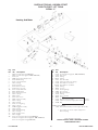
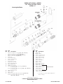
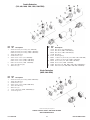
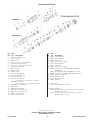
INSTRUCTIONS & PARTS LIST FOR NO. 1 SERIES
“1ST” and “1OT” PUSH TO START TOOLS
SERIAL “C”
SAVE THESE INSTRUCTIONS!
Read and understand these instructions before operating this tool.
WARNING
When used improperly power tools can create hazardous situations.
Everyone using, maintaining, changing accessories or working near this tool must read, understand and follow these Safety Instructions!
Improperly used power tools can cause injury or death.
Original
Instructions
250 Snap-on Drive • PO Box 1596 • Murphy, NC 28906 • USA • Phone: 828-835-9765 •www.siouxtools.com
SCREWDRIVER SAFETY
Screwdrivers can cause flying particles.
Proper eye protection must be worn at all times by tool user and bystanders.
Flying particles can cause eye injury.
Power tools generate noise.
Ear protection must be worn when tool noise level exceeds 85 dBA. We also recommend that ear protection be worn when the
tool noise level is below 85 dBA. See the tool’s information sheet for the noise level. Damping may help work surface from
ringing. Keep tool maintained to prevent an increase in noise. Replace the consumable/inserted tool to prevent an increase in
noise. Ensure that the muffler is still installed.
Prolonged exposure to noise can cause hearing loss.
Power tools vibrate.
Excessive vibration can cause injury. If numbness, tingling, pain or whitening of the skin occurs, stop using tool and consult a
physician. See the tool’s information sheet for the vibration level.
Prolonged exposure to vibration can cause injury.
Worn, chipped, or cracked sockets, bits, and adapters can break.
Do not use worn, chipped, or cracked sockets, bits, or adapters. Inspect the screwdriver and inserted bit periodically for damage.
Do not use a damaged screwdriver or bit.
Broken sockets, bits and adapters can cause injury.
Screwdrivers present a risk of entanglement.
Keep loose hair away from power tools and accessories. Keep hands away from moving parts of the tool and accessories. Do
not wear jewelry, loose clothing, or neckwear around power tools. Keep work area clear of cleaning rags and all items that could
become entangled with the tool. Gloves can become entangled with the rotating drive, causing broken or severed fingers.
Rotating drive sockets an drive extensions can easily entangle rubber-coated or metal reinforced gloves. Do not wear loose
fitting, cut or frayed gloves. Never hold the drive, socket or drive extension. Keep hands away from the rotating drive.
Entanglements can cause injuries.
This tool is not insulated for contact with electric power sources.
Do not use near live electric circuits. When driving screws into walls, be aware that they may have hidden electric wires.
Electric shock can cause injury.
This tool is not intended for use in a flammable or explosive atmosphere.
Do not use this tool in a flammable or explosive atmosphere.
Explosions and fire can cause injury.
Sudden and unexpected tool movement can occur when the fastener bottoms on the work.
Be sure your body position allows you to have control of the tool at all times. Make sure your footing is secure. Consult manufacturer
for proper reaction bar if movement is excessive.
When using a reaction bar:
• Be aware hands or feet can be injured if bar breaks.
• Keep hands from between bar and workpiece. Hands and fingers can be injured if caught between bar and work piece.
• Follow instructions supplied with reaction bar for proper installation and use.
Sudden and unexpected tool movement can cause injury.
Driving screws creates dust.
Do not breathe dust created when driving screws. Use approved mask. Dust and fumes generated by driving screws can cause
ill health. Consider dust created by tool and existing dust disturbed. Direct exhaust to minimize dust disturbance. Control dust
at the point of emission.
Breathing dust created when driving screws can cause injury.
Tools that are used with a suspension device can fall if they are not securely fastened to the device.
If the tool is used with a balancer or other suspension device, be sure the tool is firmly attached to the device.
Falling tools can cause injury.
Using excessive force on a tool makes it hard to control.
Do not force tool.
Hard to control tool can cause injury.

Form ZCE427A 2 Date 2017March15/H
Improper operation of the tool may cause projectile hazard.
Failure of the workpiece, accessories or the inserted bit can cause high velocity projectiles. Wear impact resistant eye
protection when operating the screwdriver. Ensure that the workpiece is securely fixed before using the screwdriver.
Projectile hazards can cause injury.
Use of the tool can expose the operators hands to hazards including crushing, impacts, cuts and abrasions.
Operators and maintenance personnel should be physically able to handle the bulk, weight, and power of the tool. Hold the tool
correctly and be ready to counteract normal or sudden movements and have both hands available. Maintain a balanced body
position and secure footing. In cases where the means to absorb the reaction torque are requested, it is recommended to use a
suspension are whenever possible. Do not use in confined spaces and beware of crushing hands between tool and workpiece,
especially when unscrewing. Release the start-and-stop device in the case of an interruption of the air supply.
Wear suitable gloves to protect hands.
Operators can experience discomfort in the hands, arms, shoulders, neck or other parts of the body.
Use a comfortable, not off-posture position. Change posture during extended tasks.
If the operator experiences persistent or recurring discomfort, pain, throbbing, aching, tingling, numbness, burning sensations or
stiffness, the operator should seek medical assistance.
Be aware of workplace hazards.
Be aware of slippery surfaces caused by the use of the tool and avoid trip hazards caused by the air line. Proceed with care in
unfamiliar surroundings. Ensure work area is free from electrical cables, gas pipes and other hazards.
Workplace hazards can cause injury.
Vibration exposure can cause disabling damage.
Wear warm clothing when working on cold conditions. Keep your hands warm and dry. Stop using the tool if you experience
numbness, tingling, pain, or whitening of the skin and contact a physician. Maintain the tool as recommended to prevent an
increase in vibration levels. Do not use worn or ill fitting sockets or extensions, as this is likely to cause a substantial increase
in vibration. Replace the consumable tool to prevent an unnecessary increase in vibration levels. Support the tool in a stand,
tensioner, or balancer if possible. Do not hold the tool too tightly. Sleeve fittings should be used where practicable. Keep
hands away from nutrunner sockets.
Only Qualified operators should install, adjust or use the screwdriver. Do not modify this tool.
Air under pressure can cause injury.
Shut of air supply, drain hose and disconnect from router before servicing or changing bits. Never direct air at yourself or
anyone else. Whipping air hoses can cause severe injury. Always check for damaged or loose hoses or fittings. Use lock pins
and whipcheck safety cables when using universal twist couplings. Do not exceed the maximum pressure stated on tool. For
torque-control tools, the air pressure has a safety critical effect on performance. Requirements for length and diameter of hose
shall be specified. Do not carry the tool by the hose. Wipe all couplers clean before connecting. Failure to do so can result in
damage to the quick couplers and cause overheating.
Whipping hoses and air pressure can cause injury.
Taping or wiring the throttle valve in the “ON” position will prevent the tool from shutting off if the tool should jam or malfunction or if
anything unexpected happens.
Do not wire or tape down the “On-Off” valve of any power tool.
Tools that are prevented from shutting off can cause injury.
Poorly maintained and lubricated tools can fail unexpectedly.
Keep tool properly lubricated and in good repair at all times. Use only Sioux Air Motor Oil No. 288. See the tool’s information
sheet to find out what other greases and oils to use. Do not drop the end of the hose on the floor where it will pick up dirt and
transport it into the tool. See information sheet for any additional maintenance requirements.
Unexpected tool failures can cause injury.
Air hoses can come loose from power tools and whip.
Inspect and do not use tools with loose or damaged air hoses or fittings.
Whipping air hoses can cause injury.
Air hoses that are not oil resistant or are not rated for the working pressure can burst.
Make sure that all air hoses are oil resistant and rated for the working pressure.
Air hoses that burst can cause injury.
Improperly repaired tools perform unpredictably.
Repair tools at an Authorized Sioux Service Center.
Tools that perform unpredictably can cause injury.
Tools left connected to the air supply while making adjustments, changing accessories, or doing any maintenance or service on tool can
start unexpectedly.
Always remove tool from air supply and activate trigger to bleed air line before making any adjustments, changing accessories,
or doing any maintenance or service on tool.
Tools starting unexpectedly can cause injury.
Working in poorly lit areas makes it hard to see hazards.
Keep work area well lit.
Poorly lit work areas can cause injury.
Children are attracted to work areas.
Keep children away. All visitors must keep a safe distance away from work area.
Children in work areas can be injured.
Unauthorized or untrained personnel can misuse unattended tools.
Store idle tools in a dry, high or locked-up place, out of the reach of children.
Misused tools can cause injury.
Tools with the actuator left in the “ON” position when an unexpected air pressure loss occurs can start unexpectedly when the air pressure is restored.
Release the actuator if an unexpected loss of air pressure occurs.
Unexpected tool starts can cause injury.
The use of any accessory with this tool not provided or specified by Sioux Tools can perform unpredictably.
Use only accessories provided or specified by Sioux Tools.
Tools that perform unpredictably can cause injury.
Avoid exposure to hazardous substances deposited on the tool.
When disposing of a tool, do it in a way that does not harm personnel or the environment.

Form ZCE427A 3 Date 2017March15/H
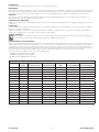
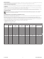
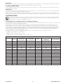
SOUND AND VIBRATION READINGS
Catalog No. Weight
(lbs/kg)
Sound Pressure dBA
(per EN ISO 15744)
Sound Power dBA
(per EN ISO 15744)
Uncertainty
(dBA)
Vibration m/s
2
(per EN ISO 28927-2)
Uncertainty m/s
2
(per EN ISO 28927-2)
1OT2108Q 2.1/1 TBD TBD TBD TBD TBD
1OT2208Q 2.1/1 72.7 84.4 3 0.27 0.02
1OT2308Q 2.1/1 75.8 87.4 3 0.24 0.01
1OT2508Q 1.9/0.9 TBD TBD TBD TBD TBD
1OTY2108 2.1/1 TBD TBD TBD TBD TBD
1OTY2208 2.1/1 TBD TBD TBD TBD TBD
1OTY2308 2.1/1 TBD TBD TBD TBD TBD
1OTY2508 1.9/0.9 TBD TBD TBD TBD TBD
1ST2108 1.6/0.7 TBD TBD TBD TBD TBD
1ST2108Q 1.6/0.7 83 94.7 3 0.58 0.03
1ST2208Q 1.6/0.7 82.9 94.5 3 0.4 0.007
1ST2308Q 1.6/0.7 85.1 96.7 3 0.3 0.004
1ST2508Q 1.4/0.6 TBD TBD TBD TBD TBD
1STY2208 1.6/0.7 TBD TBD TBD TBD TBD
1STY2308 1.6/0.7 TBD TBD TBD TBD TBD
1STY2508 1.4/0.6 TBD TBD TBD TBD TBD
INTENDED USE
This tool is intended to drive threaded fastener to join wood, metal and other materials.
MAINTENANCE
Water, dust and other airline contaminants can cause rust and vane sticking. For long periods between tool use, flush the tool with a few drops of oil and
run for 10 seconds. this well help remove contaminants and reduce the formation of rust. Check free running speed of tool and compare to nameplate
speed. If free running speed is in excess of nameplate, do not use tool. Also perform a simple check by feel to verify vibration has not increased.
AIR SUPPLY
The efficiency of the tool is dependent on the proper supply of clean dry air at 90 psig (6.2 bar). The use of a line filter, pressure regulator, and
lubricator will insure maximum output and service life of tools.
HOSE AND HOSE CONNECTIONS
Supply hose should be not less than 3/8" (10mm) I.D. Extension hoses should be at least 3/8" (10mm) I.D. Use couplings and fittings with at least 1/4"
(6.4mm) I.D.
LUBRICATION
An airline lubricator, set to deliver one drop per minute, is recommended. If a lubricator is not used, add .04 oz. (1.2cc, 12 to 15 drops) of SIOUX No.
288 air motor oil into the air inlet daily.
Lubricate the gearing every 150 hours of operation with SIOUX No. 1232A grease. Lubricate positive clutch every 25 to 50 hours with SIOUX No.
1232A grease. Lubricate torque control clutches every 25 to 50 hours with light oil.
GENERAL OPERATION
Reversing tools have a button to depress to reverse the air motor. Always depress the button fully to obtain full power. The reversing button
can be locked in the reverse direction by fully depressing and rotating the button clockwise.
TORQUE CONTROL CLUTCH OPERATION
Torque control tools will shut off when the preset torque is reached on the fastener. The tool will reset for the next cycle when removed from the fastener.
Torque control clutches are adjusted externally with the use of Sioux No. 2366 clutch adjustment wrench or a #1 (3/16", 4.8mm Dia. shank) Phillips
screwdriver. Clutch adjustment is accomplished by rotating the clutch cover until the slot in the clutch case appears. Turn the output spindle of the
tool with a 1/4 (6.4mm) hex key wrench until the groove in the adjusting washer is aligned with the slot in the clutch case. Insert the clutch adjustment
wrench into the groove and push to fully engage the teeth. Turn the clutch adjustment wrench counterclockwise to increase the torque.
Three clutch springs are available and are color coded for torque range.
#66050 green spring 2-20 in-lb (.23-2.26 N
.
m)
#66049 blue spring 15-35 in-lb (1.7-4 N
.
m)
#66048 silver spring 30-50 in-lb (3.39-5.6 N
.
m)

Form ZCE427A 4 Date 2017March15/H
ANWEISUNGEN & TEILELISTE FÜR “PUSH-TO-START” WERKZEUGE
DER NR. 1 SERIEN “1ST” UND “1OT”
SERIE “C”
Übersetzung Der Original Anleitungen
BEWAHREN SIE DIESE ANLEITUNG AUF!
Lesen Sie diese Bedienungsanleitung, bevor Sie dieses Werkzeug in Betrieb nehmen.
WARNUNG
Unsachgemäßer Gebrauch von Werkzeugen kann zu gefährlichen Situationen führen.
Jede Person, die dieses Werkzeug gebraucht, wartet, Zubehör auswechselt oder in der Nähe dieses Werkzeugs arbeitet, muss diese
Sicherheitshinweise lesen, verstanden haben und befolgen!
Unsachgemäßer Gebrauch von Werkzeugen kann zu Verletzungen oder zum Tod führen.

Form ZCE427A 5 Date 2017March15/H

Form ZCE427A 6 Date 2017March15/H
DRUCKLUFTZUFUHR
Die Werkzeugleistung hängt von der ordnungsgemäßen Zufuhr von sauberer, trockener Luft mit einem Druck von 6,2 bar (90 psig) ab. Die Verwendung
von Filtern, Druckregulierern und Schmiervorrichtungen gewährleistet eine maximale Werkzeugleistung und -lebensdauer.
SCHLAUCH UND SCHLAUCHANSCHLÜSSE
Der Zufuhrschlauch sollte einen Mindest-Innendurchmesser von 5/16” (7,9 mm) aufweisen. Verlängerungsschläuche müssen einen Innendurchmesser
von mindestens 3/8” (10 mm) haben. Kupplungen und Armaturen müssen ebenfalls einen Mindest-Innendurchmesser von 5/16” (7,9 mm) aufweisen.
SCHMIERUNG
Es wird eine Luftschlauch-Schmiervorrichtung empfohlen, die einen Tropfen pro Minute abgibt. Wenn keine Schmiervorrichtung eingesetzt wird, füllen
Sie täglich 1,2 ml ( oder 12 bis 15 Tropfen) SIOUX Druckluftmotoröl Nr. 288 in den Drucklufteinlaß.
Schmieren Sie das Getriebe nach jeweils 150 Stunden Betrieb mit SIOUX Schmiermittel Nr. 1232A. Schmieren Sie alle positiven Kupplungen alle 25 bis
50 Stunden mit SIOUX Schmiermittel Nr. 1232A. Schmieren Sie die Drehmomentkontrollkupplungen alle 25 bis 50 Stunden mit leichtem Öl.
ALLGEMEINER BETRIEB
Umschaltbare Werkzeuge weisen einen Druckknopf zur Umkehr der Laufrichtung des Druckluftmotors auf. Drücken Sie diesen Knopf immer
komplett nach ein, um die volle Leistung zu erreichen. Der Umkehrknopf wird in der Umkehrlaufrichtung eingerastet, indem er komplett
eingedrückt und im Uhrzeigersinn gedreht wird.
DREHMOMENTKONTROLLE UND BETRIEB MIT JUSTIERBARER KUPPLUNG
Werkzeuge mit Drehmomentkontrolle schalten automatisch ab, wenn das eingestellte Drehmoment erreicht wird. Das Werkzeug setzt für den nächsten
Zyklus zurück, wenn es aus der Halterung entnommen wird.
Kupplungen mit Drehmomentkontrolle werden mit einem Justierschlüssel Sioux Nr. 2366 oder einem #1 (3/16” bzw. 4,8 mm Schaftdurchmesser)
Kreuzschlitz-Schraubendreher extern eingestellt. Die Kupplungsjustierung wird erreicht, indem die Kupplungsabdeckung bis zum Erscheinen des
Schlitzes im Kupplungsgehäuse rotiert wird. Drehen Sie die Werkzeugwelle mit einem 1/4” (6,4 mm) Sechskantschlüssel, bis die Nut der Justierscheibe
auf dem Schlitz im Kupplungsgehäuse ausgerichtet ist. Führen Sie den Kupplungsjustierschlüssel in die Nut ein, und drücken Sie, um die Zähne voll
einrasten zu lassen. Drehen Sie den Justierschlüssel gegen den Uhrzeigersinn, um das Drehmoment zu erhöhen.
Es sind drei Kupplungsfedern erhältlich. Sie sind je nach Drehmomentbereich farblich markiert.
#66050 grüne Feder 2-20 in-lb (0,23-2,26 Nm)
#66049 blaue Feder 15-35 in-lb (1,7-4 Nm)
#66048 silberne Feder 30-50 in-lb (3,39-5,6 Nm)
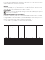
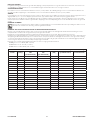
SCHALL- UND VIBRATIONSWERTE
Katalog Nr.
Weight
(lbs/kg)
Lärmdruckpegel
dBA
(per EN ISO 15744)
Lärmleistungspegel
dBA
(per EN ISO 15744)
Ungewissheit
(dBA)
Vibrationspegel
m/s
2
(per EN ISO 28927-2)
Ungewissheit m/s
2
(per EN ISO 28927-2)
1OT2108Q 2,1/1 TBD TBD TBD TBD TBD
1OT2208Q 2,1/1 72,7 84,4 3 0,27 0,02
1OT2308Q 2,1/1 75,8 87,4 3 0,24 0,01
1OT2508Q 1,9/0,9 TBD TBD TBD TBD TBD
1OTY2108 2,1/1 TBD TBD TBD TBD TBD
1OTY2208 2,1/1 TBD TBD TBD TBD TBD
1OTY2308 2,1/1 TBD TBD TBD TBD TBD
1OTY2508 1,9/0,9 TBD TBD TBD TBD TBD
1ST2108 1,6/0,7 TBD TBD TBD TBD TBD
1ST2108Q 1,6/0,7 83 94,7 3 0,58 0,03
1ST2208Q 1,6/0,7 82,9 94,5 3 0,4 0,007
1ST2308Q 1,6/0,7 85,1 96,7 3 0,3 0,004
1ST2508Q 1,4/0,6 TBD TBD TBD TBD TBD
1STY2208 1,6/0,7 TBD TBD TBD TBD TBD
1STY2308 1,6/0,7 TBD TBD TBD TBD TBD
1STY2508 1,4/0,6 TBD TBD TBD TBD TBD

Form ZCE427A 7 Date 2017March15/H
INSTRUCCIONES Y LISTA DE PARTES PARA LAS HERRAMIENTAS
“PUSH TO START” SERIE NO 1 “1S T” y “1OT”
SERIE “C”
Traducción De Las Instrucciones Originales
¡NO PIERDA ESTAS INSTRUCCIONES!
Lea y entienda estas instrucciones antes de usar esta herramienta.
ADVERTENCIA
Una herramienta motorizada puede ser peligrosa si no se usa correctamente.
¡Las personas que vayan a usar la herramienta, darle mantenimiento, quitar o poner accesorios o trabajar cerca de la herramienta
deben leer, entender y respetar estas instrucciones de seguridad!
Una herramienta motorizada que no se use correctamente puede provocar lesiones o fatalidades.

Form ZCE427A 8 Date 2017March15/H

Form ZCE427A 9 Date 2017March15/H
SUMINISTRO DE AIRE
La eficiencia de la herramienta depende de un suministro adecuado de aire seco a 90 psig (6,2 bar). El uso de un filtro de línea, regulador de presión,
y un lubricador garantizará un máximo rendimiento y vida útil de la herramienta.
MANGUERA Y CONEXIONES DE LA MANGUERA
La manguera de distribución debe tener no menos de 5/16” (7,9 mm) de diámetro interno. La extensión de la manguera debe ser al menos de 3/8” (10
mm) de diámetro interno. Utilice acoplamientos y piezas con un diámetro interno de al menos 5/16” (7,9 mm).
LUBRICACION
Se recomienda que un lubricador de tubo de aire distribuya una gota por minuto. Si no se utiliza el lubricador, agregue, diariamente en la entrada de
aire 0,04 oz (1,2 cc, 12 a 15 gotas) de aceite para motores neumáticos No 288 SIOUX.
Lubrique el engranaje con grasa No 1232A de SIOUX cada 150 horas de funcionamiento. Lubricar el embrague positivo cada 25 a 50 horas con grasa
SIOUX No 1232A. Lubrique el control de torsión de embragues cada 25 a 50 horas con aceite ligero.
INFORMACION GENERAL
Las herramientas con reversa tienen un botón que se debe oprimir para revertir el motor neumático. Siempre oprima el botón completamente
para obtener la potencia máxima. El botón para reversa puede ser asegurado en la dirección inversa, oprimiendo y girando completamente
el botón en el sentido de las agujas del reloj.
FUNCIONAMIENTO DEL EMBRAGUE AJUSTABLE Y CONTROL DE TORSION
Las herramientas con control de torsión se detendrán cuando se alcanza la torsión preestablecida en el sujetador. La herramienta se reajustará para
el siguiente ciclo cuando se saque del sujetador.
Los embragues de control de torsión son ajustados externamente con una llave de ajuste de embrague SIOUX No 2366 #1 o un destornillador Phillips
#1 (3/16”, 4,8mm de diámetro de espiga). El ajuste del embrague se logra girando la cubierta del embrague hasta que aparezca la muesca en la caja
del embrague. Gire el eje motor de la herramienta con una llave hexagonal de ¼” (6,4 mm) hasta que el surco en la arandela de ajuste esté alineada
con la muesca en la caja del embrague. Inserte la llave para ajuste del embrague en el surco y empuje para engranar completamente los dientes.
Gire la llave de ajuste del embrague en el sentido contrario a las agujas del reloj para aumentar la torsión.
Se encuentran disponibles tres resortes de embrague y están codificados por color según el rango de torsión.
#66050 resorte verde 2-20 in-lb (.23-2,26 Nm)
#66049 resorte azul 15-35 in-lb (1,7-4 Nm)
#66048 resorte plateado 30-50 in-lb (3,39-5,6 Nm)
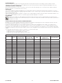
LECTURA DE VIBRACIONES Y SONIDOS
No de
Catalogo
Weight
(lbs/kg)
Nivel de presión de
sonido dBA
(per EN ISO 15744)
Nivel de potencia
de sonido dBA
(per EN ISO 15744)
Incertidumbre
(dBA)
Nivel de vibración m/s
2
(per EN ISO 28927-2)
Incertidumbre m/s
2
(per EN ISO 28927-2)
1OT2108Q 2,1/1 TBD TBD TBD TBD TBD
1OT2208Q 2,1/1 72,7 84,4 3 0,27 0,02
1OT2308Q 2,1/1 75,8 87,4 3 0,24 0,01
1OT2508Q 1,9/0,9 TBD TBD TBD TBD TBD
1OTY2108 2,1/1 TBD TBD TBD TBD TBD
1OTY2208 2,1/1 TBD TBD TBD TBD TBD
1OTY2308 2,1/1 TBD TBD TBD TBD TBD
1OTY2508 1,9/0,9 TBD TBD TBD TBD TBD
1ST2108 1,6/0,7 TBD TBD TBD TBD TBD
1ST2108Q 1,6/0,7 83 94,7 3 0,58 0,03
1ST2208Q 1,6/0,7 82,9 94,5 3 0,4 0,007
1ST2308Q 1,6/0,7 85,1 96,7 3 0,3 0,004
1ST2508Q 1,4/0,6 TBD TBD TBD TBD TBD
1STY2208 1,6/0,7 TBD TBD TBD TBD TBD
1STY2308 1,6/0,7 TBD TBD TBD TBD TBD
1STY2508 1,4/0,6 TBD TBD TBD TBD TBD

Form ZCE427A 10 Date 2017March15/H
ISTRUZIONI E LISTA RICAMBI PER LA SERIE 1 DEGLI APPARECCHI A PRESSIONE “1ST” e “1OT”
SERIE “C”
Traduzione Delle Istruzioni Originali
CONSERVARE QUESTE ISTRUZIONI!
Leggere attentamente queste istruzioni prima di usare l'attrezzo.
AVVERTIMENTO
Utensili a motore non usati correttamente possono creare condizioni di rischio..
Chiunque usi, mantenga, sostituisca accessori o lavori vicino a quest’utensile deve leggere attentamente e seguire
queste istruzioni di sicurezza!
L’uso diverso dal previsto di questi utensili a motore può causare infortuni o decesso.

Form ZCE427A 11 Date 2017March15/H

Form ZCE427A 12 Date 2017March15/H
ALIMENTAZIONE ARIA
L’efficienza dell’apparecchio dipende da un’adeguata alimentazione di aria pulita ad una pressione di 90 psig (6,2 bar). L’utilizzo di un filtro
sull’impianto, di un regolatore di pressione e di un lubrificante assicurano la massima fuoriuscita d’aria e la lunga durata dell’apparecchio stesso.
TUBAZIONE ED APPOSITE CONNESSIONI
Il D.I del tubo di alimentazione non deve essere inferiore a 5/16” (7,9 mm). Il D.I. delle prolunghe deve essere di almeno 3/8” (10 mm). Adoperare
giunzioni e connettori con un D.I. di almeno 5/16” (7,9 mm.).
LUBRIFICANTE
Si raccomanda l’utilizzo di un impianto di lubrificazione, per circuiti ad aria compressa, regolato alla velocità di una goccia al minuto. Se non viene
utilizzato alcun impianto di lubrificazione aggiungere giornalmente 0,4 once (1,2 cc, da 12 a 15 gocce) di olio per motori ad aria Sioux n. 288 all’interno
della cassetta di aspirazione aria.
Lubrificare gli ingranaggi ogni 150 ore di utilizzo con il grasso Sioux n. 1232A. Lubrificare le frizione ad innesto dentato ad intervalli di 25-50 ore con il
grasso Sioux n.1232A. Lubrificare le frizioni con controllo di coppia ad intervalli di 25-50 ore con olio fluido.
USO GENERALE
Gli apparecchi reversibili sono dotati di pulsante per invertire la rotazione del motore. Premere sempre il pulsante a fondo per ottenere la
massima potenza. Il pulsante per invertire la rotazione può essere bloccato nella posizione di rotazione inversa premendolo completamente e
ruotandolo in senso orario.
USO DEL CONTROLLO DI COPPIA E DELLA FRIZIONE REGOLABILE
Gli apparecchi con controllo di coppia si arrestano da soli quando viene raggiunto sulla parte girevole il valore di coppia preselezionato. Una volta
rimosso dalla parte girevole, l’apparecchio si resetta per il ciclo successivo.
Le frizioni di controllo di coppia possono essere regolate esternamente usando la chiave di regolazione Sioux n. 2366 o un cacciavite a croce
Phillips (3/16, 4,8 mm di diam. taglio). Per effettuare tale regolazione ruotare il coperchio della frizione fino a che non appare l’apposita fessura sul
pacco frizione stesso. Girare l’alberino di uscita dell’apparecchio con una chiave esagonale da 1,4” (6,4 mm) fino a che la scanalatura sulla rondella
regolabile si trovi allineata con la fessura sul pacco frizione. Inserire la chiave di regolazione nella scanalatura e premere per innescare completamente
i dentini.
Sono disponibili tre tipi di molle frizione in diverse colorazioni a secondo dei valori di coppia
n. 66050 molla verde da 2 a 20 pollici-libbra (da 0,23 a 2,26 Nm)
n. 66049 molla blu da 15 a 35 pollici-libbra (da 1,7a 4 Nm)
n. 66048 molla argento da 30 a 50 pollici-libbra (da 3,39 a 5,6 Nm)
VALORI DI RUMOROSITA’ E VIBRAZIONI
Catalogo n.
Weight
(lbs/kg)
Livello di pressione
del suono dBA
(per EN ISO 15744)
Livello di potenza
del suono dBA
(per EN ISO 15744)
Incertezza
(dBA)
Livello di
vibrazioni m/s
2
(per EN ISO 28927-2)
Incertezza m/s
2
(per EN ISO 28927-2)
1OT2108Q 2,1/1 TBD TBD TBD TBD TBD
1OT2208Q 2,1/1 72,7 84,4 3 0,27 0,02
1OT2308Q 2,1/1 75,8 87,4 3 0,24 0,01
1OT2508Q 1,9/0,9 TBD TBD TBD TBD TBD
1OTY2108 2,1/1 TBD TBD TBD TBD TBD
1OTY2208 2,1/1 TBD TBD TBD TBD TBD
1OTY2308 2,1/1 TBD TBD TBD TBD TBD
1OTY2508 1,9/0,9 TBD TBD TBD TBD TBD
1ST2108 1,6/0,7 TBD TBD TBD TBD TBD
1ST2108Q 1,6/0,7 83 94,7 3 0,58 0,03
1ST2208Q 1,6/0,7 82,9 94,5 3 0,4 0,007
1ST2308Q 1,6/0,7 85,1 96,7 3 0,3 0,004
1ST2508Q 1,4/0,6 TBD TBD TBD TBD TBD
1STY2208 1,6/0,7 TBD TBD TBD TBD TBD
1STY2308 1,6/0,7 TBD TBD TBD TBD TBD
1STY2508 1,4/0,6 TBD TBD TBD TBD TBD

Form ZCE427A 13 Date 2017March15/H
INSTRUCTIONS D’UTILISATION ET LISTE DES PIECES DETACHEES DES OUTILS DE
MISE EN MARCHE PAR PRESSION, PREMIERE SERIE “1ST” ET “1OT”
SÉRIE “C”
Traduction Des Instructions Originales
CONSERVEZ CES INSTRUCTIONS !
Veuillez lire et comprendre ces instructions avant d'utiliser cet outil.
AVERTISSEMENT
Une utilisation incorrecte d’outils électriques risque d’engendrer des situations dangereuses.
Toute personne susceptible d’utiliser, d’entretenir, de remplacer des accessoires ou de travailler à proximité de cet outil doit avoir lu
et compris les instructions de sécurité ci-après et s’y conformer !
Une utilisation incorrecte d’outils électriques risque de provoquer des dommages corporels, voire même la mort.

Form ZCE427A 14 Date 2017March15/H

Form ZCE427A 15 Date 2017March15/H
APPORT D’AIR
L’efficacité de votre outil dépendra en grande partie de la nature de l’apport d’air : cet air doit être sec et propre à 90 psi manométrique. L’usage d’un
filtre, régulateur et lubrificateur vous assureront des meilleures performances et longévité des outils.
LE TUYAU ET SON BRANCHEMENT
Le tuyau d’apport d’air doit être au moins de 7,9 mm de D. int. et la rallonge de 10 mm. Les couples de serrage et les raccords doivent être, quant à
eux, d’au moins 7,9 mm de D. int.
LUBRIFICATION
Il est vivement conseillé d’utiliser un lubrificateur d’air, réglé à une goutte par minute. Sinon, ajoutez chaque jour, 1,2 c
3
(entre 12 et 15 gouttes) d’huile
pour moteurs pneumatiques No. 288 de SIOUX dans l’entrée d’air.
Lubrifier l’engrènement avec du lubrifiant No. 1232A de SIOUX toutes les cent cinquante heures d’utilisation. Lubrifiez le embrayage d’entraînement
instantané toutes les 25-50 heures avec du lubrifiant No. 1232A de SIOUX. Lubrifiez aussi les embrayages de commande de couple toutes les 25-50
heures à l’aide d’une huile légère.
FONCTIONNEMENT GENERAL
Les mécanismes à inversion de sens de marche disposent d’un bouton qui permet d’inverser le sens de la marche du moteur pneumatique.
Appuyez bien sur le bouton pour en obtenir la puissance maximale. Ce bouton peut être verrouillé en marche arrière par simple pression et
rotation du bouton en sens inverse des aiguilles d’une montre.
FONCTIONNEMENT DE LA COMMANDE DE COUPLE ET L’EMBRAYAGE REGLABLE
Les outils qui disposent de la commande de couple de serrage s’arrêteront lorsque le couple prédéfini est atteint contre la fixation. Il se remettra à zéro
pour le prochain cycle, lorsqu’il sera dégagé de la fixation.
Les embrayages de commande de couple s’ajustent à l’aide d’une clé de réglage de la garde d’embrayage No. 2366 de Sioux ou d’un tournevis
Phillips #1 (diamètre de tronc de 4,8 mm). Le réglage de l’embrayage s’effectue en faisant tourner le plateau de fermeture d’embrayage jusqu’à ce
que la fente du carter d’embrayage apparaisse. Tournez la broche de sortie de l’outil à l’aide de la clé mâle pour vis à six pans creux (6,4 mm) jusqu’à
ce que la rainure de la rondelle de réglage soit alignée à la fente du carter d’embrayage. Insérez la clé de réglage de la garde d’embrayage dans
la rainure et appuyez complètement pour l’engager dans le secteur denté. Faites tourner la clé de réglage de la garde d’embrayage dans le sens
inverse des aiguilles d’une montre pour augmenter le couple.
Vous avez le choix entre trois ressorts d’embrayage, chacun ayant une couleur bien spécifique pour chaque plage de couple :
#66050 ressort vert 2-20 pouce-livre (0,23-2,26 nm)
#66049 ressort bleu 15-35 pouce-livre (1,7-4 nm)
#66048 ressort de couleur argentée 30-50 pouce-livre (3,39-5,6 nm)
NIVEAUX ACOUSTIQUES ET VIBRATOIRES
Catalog No.
Weight
(lbs/kg)
Niveau de pression
acoustique dBA
(per EN ISO 15744)
Niveau de puissance
acoustique dBA
(per EN ISO 15744)
Incertitude
(dBA)
Niveau de
vibration m/s
2
(per EN ISO 28927-2)
Incertitude m/s
2
(per EN ISO 28927-2)
1OT2108Q 2,1/1 TBD TBD TBD TBD TBD
1OT2208Q 2,1/1 72,7 84,4 3 0,27 0,02
1OT2308Q 2,1/1 75,8 87,4 3 0,24 0,01
1OT2508Q 1,9/0,9 TBD TBD TBD TBD TBD
1OTY2108 2,1/1 TBD TBD TBD TBD TBD
1OTY2208 2,1/1 TBD TBD TBD TBD TBD
1OTY2308 2,1/1 TBD TBD TBD TBD TBD
1OTY2508 1,9/0,9 TBD TBD TBD TBD TBD
1ST2108 1,6/0,7 TBD TBD TBD TBD TBD
1ST2108Q 1,6/0,7 83 94,7 3 0,58 0,03
1ST2208Q 1,6/0,7 82,9 94,5 3 0,4 0,007
1ST2308Q 1,6/0,7 85,1 96,7 3 0,3 0,004
1ST2508Q 1,4/0,6 TBD TBD TBD TBD TBD
1STY2208 1,6/0,7 TBD TBD TBD TBD TBD
1STY2308 1,6/0,7 TBD TBD TBD TBD TBD
1STY2508 1,4/0,6 TBD TBD TBD TBD TBD

Form ZCE427A 16 Date 2017March15/H
INSTRUCTIES EN ONDERDELENLIJST VOOR MACHINES MET EEN DRUKSTARTINRICHTING
“1OT” EN MACHINES UIT DE SERIE N° 1 “1ST”
SERIENUMMER “C”
Vertaling Van De Oorspronkelijke Instructies
BEWAAR DEZE INSTRUCTIES!
Zorg dat u deze instructies hebt gelezen en begrepen voordat u dit gereedschap gebruikt.
WAARSCHUWING
Bij verkeerd gebruik kunnen elektrische werktuigen gevaarlijke situaties teweegbrengen.
Iedereen die accessoires gebruikt, onderhoudt of vervangt of nabij dit werktuig werkt, moet deze veiligheidsinstructies hebben
gelezen, begrepen en volgen!
Verkeerd gebruikte elektrische werktuigen kunnen letsel of de dood veroorzak.

Form ZCE427A 17 Date 2017March15/H

Form ZCE427A 18 Date 2017March15/H
PERSLUCHTTOEVOER
Het gebruik van droge perslucht met de geschikte druk (90 psig / 6,2 bar) is bepalend voor een goed rendement van de machine. Het monteren van
een leidingfilter, een drukregelventiel en een smeerinstallatie zorgt voor maximaal rendement en een lange levensduur.
SLANG EN KOPPELINGEN
De hoofdtoevoer moet een minimale binnendiameter van 5/16” (7,9 mm) hebben. De verbindingsslangen moeten een minimale binnendiameter van
3/8” (10 mm) hebben. Koppelingen en aansluitstukken moeten een minimale binnendiameter van 5/16” (7,9 mm) hebben.
SMERING
Het is aanbevolen om een persluchtsmeersysteem te voorzien en dit af te stellen op één druppel smeerstof per minuut. Is dit niet mogelijk, dan moet er
dagelijks 0,04 oz (1,2 cc +/- 12 à 15 druppels) persluchtmotorolie, type SIOUX N° 288, in de luchtaanvoeropening gedaan worden.
Na elke werkcyclus van 150 uur moet de tandwielkast opnieuw met SIOUX N° 1232A vet gevuld worden. Positieve koppelingen moeten na 25 of 50
werkuren opnieuw met SIOUX N° 1232A vet gevuld worden. Koppelingen met momentbeperking moeten om de 25 tot 50 uur met lichte olie gesmeerd
worden.
BEDIENING: ALGEMEEN
Machines die ook achteruit kunnen draaien hebben een aparte drukknop voor achteruit draaien. Door de knop volledig in te drukken en hem
dan naar rechts te draaien kan de richting “achteruit” geblokkeerd worden.
BEDIENING: HET AFSTELLEN VAN HET KOPPEL EN VAN DE REGELBARE KOPPELING
Machines met momentbeperking schakelen uit als het van tevoren ingestelde koppel in de werktuighouder bereikt wordt. Het werktuig moet eerst
verwijderd worden voordat er met de volgende werkcyclus begonnen kan worden.
Koppelingen met momentbeperking worden van buitenaf ingesteld met behulp van een Sioux N° 2366 moersleutel of met een N° 1
kruiskopschroevendraaier (Phillips met schachtdiameter: 3/16”- 4,8 mm). Draai het deksel van de koppeling zover opzij tot de sleuf in de behuizing van
de koppeling zichtbaar wordt. Met behulp van een inbussleutel van 1/4” (6,4 mm) draait u de werktuigas van de machine, tot de groef in de instelring
en de sleuf in de behuizing samenvallen. Steek nu de instelsleutel zover mogelijk in de groef (de sleuteltanden moeten maximaal ingrijpen). Draai de
sleutel nu tegen de wijzers van de klok in waarbij het koppel opgevoerd wordt.
Er zijn drie veren voor drie aparte koppelbereiken. Elke veer heeft een eigen genormaliseerde kleur.
#66050 groene veer 2 - 20 in-lb (0,23 - 2,26 Nm)
#66049 blauwe veer 15 - 35 in-lb (1,7 - 4 Nm)
#66048 zilveren veer 30 - 50 in-lb (3,39 - 5,6 Nm)
GELUIDS- EN TRILLINGSNIVEAUS
Catalogus-
nummer
Weight
(lbs/kg)
Geluidsdrukniveau
dBA
(per EN ISO 15744)
Geluidskrachtniveau
dBA
(per EN ISO 15744)
Onzekerheid
(dBA)
Trillingsniveau m/s
2
(per EN ISO 28927-2)
Onzekerheid m/s
2
(per EN ISO 28927-2)
1OT2108Q 2,1/1 TBD TBD TBD TBD TBD
1OT2208Q 2,1/1 72,7 84,4 3 0,27 0,02
1OT2308Q 2,1/1 75,8 87,4 3 0,24 0,01
1OT2508Q 1,9/0,9 TBD TBD TBD TBD TBD
1OTY2108 2,1/1 TBD TBD TBD TBD TBD
1OTY2208 2,1/1 TBD TBD TBD TBD TBD
1OTY2308 2,1/1 TBD TBD TBD TBD TBD
1OTY2508 1,9/0,9 TBD TBD TBD TBD TBD
1ST2108 1,6/0,7 TBD TBD TBD TBD TBD
1ST2108Q 1,6/0,7 83 94,7 3 0,58 0,03
1ST2208Q 1,6/0,7 82,9 94,5 3 0,4 0,007
1ST2308Q 1,6/0,7 85,1 96,7 3 0,3 0,004
1ST2508Q 1,4/0,6 TBD TBD TBD TBD TBD
1STY2208 1,6/0,7 TBD TBD TBD TBD TBD
1STY2308 1,6/0,7 TBD TBD TBD TBD TBD
1STY2508 1,4/0,6 TBD TBD TBD TBD TBD

Form ZCE427A 19 Date 2017March15/H
ANVISNINGAR OCH RESERVDELSLISTA FÖR PUSH-TO-START-VERKTYG (tryck-och-starta) SERIE NR
1 “1ST” och “1OT”
SERIE “C”
Översätt Från Original Instruktionerna
SPARA DESSA ANVISNINGAR!
Läs och förstå dessa anvisningar innan du använder detta verktyg.
VARNING
Felaktig användning av motordrivna verktyg kan förorsaka risksituationer.
Alla som använder, underhåller, byter tillbehör på eller arbetar nära detta verktyg måste läsa, sätta sig in i och följa dessa
säkerhetsanvisningar!
Felaktig användning av motordrivna verktyg kan förorsaka personskada eller dödsfall..

Form ZCE427A 20 Date 2017March15/H
La pagina si sta caricando...
La pagina si sta caricando...
La pagina si sta caricando...
La pagina si sta caricando...
La pagina si sta caricando...
La pagina si sta caricando...
La pagina si sta caricando...
La pagina si sta caricando...
La pagina si sta caricando...
La pagina si sta caricando...
-
 1
1
-
 2
2
-
 3
3
-
 4
4
-
 5
5
-
 6
6
-
 7
7
-
 8
8
-
 9
9
-
 10
10
-
 11
11
-
 12
12
-
 13
13
-
 14
14
-
 15
15
-
 16
16
-
 17
17
-
 18
18
-
 19
19
-
 20
20
-
 21
21
-
 22
22
-
 23
23
-
 24
24
-
 25
25
-
 26
26
-
 27
27
-
 28
28
-
 29
29
-
 30
30


Sioux Tools 1 series Istruzioni per l'uso
- Categoria
- Utensili elettrici
- Tipo
- Istruzioni per l'uso
in altre lingue
- English: Sioux Tools 1 series Operating instructions
- français: Sioux Tools 1 series Mode d'emploi
- Nederlands: Sioux Tools 1 series Handleiding
Documenti correlati
-
Sioux Tools SSD4P14S Manuale del proprietario
-
-
-
Sioux Tools SWGA1AX124G Istruzioni per l'uso
-
Sioux Tools SDR6P12N3 Istruzioni per l'uso
-
Sioux Tools SAGA1AX12G Istruzioni per l'uso
-
-
-
