SilverStone SG05-LITE Manuale del proprietario
- Categoria
- Custodie per computer
- Tipo
- Manuale del proprietario
La pagina sta caricando ...
La pagina sta caricando ...
La pagina sta caricando ...
La pagina sta caricando ...

3
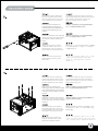
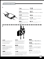
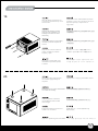
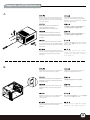
Please remove the screws holding
the top cover with a screw driver,
then pull it toward the back to lift it
outward away from the chassis.
С помощью отвертки открутите
шурупы, удерживающие верхнюю
крышку, а затем снимите ее, сдвинув
назад и приподняв.
Bitte entfernen Sie die Schrauben der
oberen Abdeckung mit einem
Schraubenzieher und ziehen Sie die
Abdeckung nach hinten, weg von dem
Chassis.
Veuillez retirer les vis tenant le panneau
supérieur avec un tournevis, puis tirez-le
vers l’arrière afin de le soulever en
dehors du boîtier.
Por favor, quite los tornillos que
sujetan la cubierta superior con un
destornillador, luego tire de ella hacia
atrás para quitarla del chasis.
Rimuovere le viti del pannello
superiore con un cacciavite, spingerlo
verso la parte posteriore e sollevarlo
per asportarlo dal telaio.
상부 커버를 고정하고 있는 나사를
스크류 드라이버를 이용해 제거한 후,
뒤쪽으로 당겨 들어 올려, 케이스로
부터 제거합니다.
請以螺絲起子將鎖固上蓋的螺絲卸下,
並向後拉後提起以自機殼中取出。
请以螺丝起子将锁固上盖的螺丝卸下,
并向后拉后提起以自机壳中取出。
上部カバーを固定しているネジをドライバ
ーで外し、カバーを後方に引いてケースか
ら取り外します。
Install PSU into the case as shown. Установите блок SFX питания в
корпус, как показано на рисунке
Installieren Sie das SFX Netzteil wie
dargestellt im Gehäuse.
Installez l'SFX alimentation dans le
boîtier comme montré
Instale la SFX FA en la carcasa
como se muestra
Installare l’SFX alimentatore come
mostrato
그림에서와 같이 SFX PSU를 케이스에
장착합니다.
請依圖示將SFX電源放入機殼內。
请依图示将SFX电源放入机壳内。
図のように、ケースの中にSFX PSUを
インストールし。

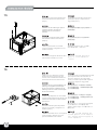
Remove the screws holding the
hard drive bracket with a screw
driver as shown, then remove the
cage outward from the chassis.
С помощью отвертки открутите шурупы,
удерживающие кронштейн жесткого диска,
как показано на рисунке, и выньте из
корпуса корзину жесткого диска.
Entfernen Sie die Schrauben der
Festplattenhalterung mithilfe eines
Schraubenziehers wie abgebildet und
nehmen Sie die Halterung aus dem
Chassis.
Retirez les vis fixant le casier à disques
durs avec un tournevis comme montré,
puis retirez le casier à l’extérieur du
boîtier
Retire los tornillos que sujetan
el bracket del disco duro con un
destornillador como se muestra,
luego saque la carcasa del chasis.
Rimuovere le viti che fissano la
gabbia degli hard drive, quindi
rimuoverla.
하드디스크 브라켓을 고정하고 있는 나사를
스크류 드라이버를 이용해 그림과 같이
제거한 후, 케이지를 케이스 바깥으로
제거합니다.
請依圖示先以螺絲起子將鎖固硬碟架的螺絲
卸下,再將硬碟架自機殼中取出。
请依图标先以螺丝起子将锁固硬盘架的螺丝
卸下,再将硬盘架自机壳中取出。
図のようにハードディスクドライブブラケットを固定
しているネジをドライバーで外し、ケースからケー
ジを取り出します。
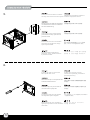
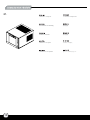
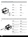
Remove the screws holding the
optical drive bracket with a screw
driver as shown, then remove the
bracket outward from the chassis.
С помощью отвертки открутите шурупы,
удерживающие кронштейн оптического
диска, как показано на рисунке, и выньте
кронштейн из корпуса.
Entfernen Sie die Schrauben der
Halterung für optische Laufwerke mithilfe
eines Schraubenziehers wie abgebildet
und nehmen Sie die Halterung aus dem
Chassis.
Retirez les vis fixant le casier à lecteur
optique slim avec un tournevis comme
montré, puis retirez le casier à l’extérieur
du boîtier
Quite los tornillos que sujetan el
bracket del dispositivo óptico con
un destornillador como se muestra,
luego quite el bracket del chasis.
Rimuovere le viti che fissano il
supporto dei lettori ottici, quindi
rimuovere il supporto stesso.
광드라이브 브라켓을 고정하고 있는 나사를
스크류 드라이버를 이용해 그림과 같이 제거
한후, 브라켓을 케이스 바깥쪽으로 제거합니다.
依圖示先以螺絲起子將鎖固光碟機架的螺絲
卸下,再將光碟機架自機殼中取出。
依图标先以螺丝起子将锁固光驱架的螺丝卸下,
再将光驱架自机壳中取出。
図のように光学ドライブブラケットを固定している
ネジをドライバーで外し、ケースからブラケットを
取り外します。

5
Press the area as shown to release
the clips, then remove the front panel.
Нажмите на указанные зажимы и
снимите переднюю панель.
Drücken Sie auf die Stelle wie abgebildet,
um die Klemmen zu lösen und entfernen
Sie die Frontabdeckung.
Appuyez sur la zone comme montré
pour détacher les clips, puis retirez le
panneau frontal.
Presione la zona como se muestra
para soltar los enganches, luego
quite el panel frontal.
Premere nell’area indicata per
sbloccare i fermi, quindi rimuovere
il pannello frontale
그림에서와 같은 위치를 눌러 클립을
풀어준 후, 전면 패널을 제거합니다.
請依圖示輕按卡榫以卸下前面板。
请依图示轻按卡榫以卸下前面板。
図に示された場所を押してクリップを開
放し、フロントパネルを取り外します。
Pull the clip apart to remove the
slim optical drive cover.
Чтобы снять крышку тонкого
оптического привода, разомкните
крепежную клипсу.
Öffnen Sie den Clip um das optische Slim
Laufwerk herauszunehmen.
Tirez sur le clip pour pouvoir retirer le
cache du lecteur optique slim.
Tire del clip para sacar la cubierta
del dispositivo óptico delgado.
Rimuovere le viti come mostrato in
figura per asportare il cover del lettore
ottico slim.
클립을 당겨 슬림 광 드라이브의
커버를 제거하세요.
請卸下圖示中的將光碟機槽檔板自機殼
中取出。
请卸下图标中的将光驱槽文件板自机壳
中取出。
クリップを外して、スリム光学ドライブのカバ
ーを取り外します。
5.
6.

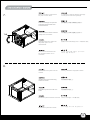
Remove the tab of optical drive
bay with a screw driver.
С помощью отвертки уберите накладку
отсека для оптического привода.
Entfernen Sie Klappe des optischen
Laufwerkschachtes mithilfe eines
Schraubenziehers.
Retirez l’attache de la baie du lecteur
optique avec un tournevis.
Quite la presilla de la bahía del
dispositivo óptico con un
destornillador.
Rimuovere la mascherina del
bay del lettore ottico con un
cacciavite.
스크류 드라이버를 이용해, 광드라이브
베이의 탭을 제거합니다.
請以螺絲起子折斷光碟機槽上的檔片。
请以螺丝起子折断光驱槽上的文件片。
光学ドライブベイのタブをドライバーで取り外します。
Reinstall the front panel onto the
chassis.
Снова установите переднюю панель.
Installieren Sie die Frontabdeckung
wieder am Chassis.
Réinstallez le panneau frontal sur le
boîtier.
Reinstale el panel frontal en el chasis.
Reinstallare il pannello frontale.
전면 패널을 케이스에 재 설치합니다.
將前面板裝回機殼上。
将前面板装回机壳上。
フロントパネルをケースに戻します。
6
7.
8.
TAB

7
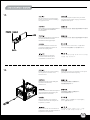
Install your motherboard into the
chassis as shown and secure with
included screws.
Установите материнскую плату в
корпус и закрепите ее прилагаемыми
шурупами.
Installieren Sie Ihr Motherboard im Chassis
und befestigen Sie es mit den beiliegenden
Schrauben.
Retirez l’attache de la baie du lecteur
optique avec un tournevis.
Instale su placa base en el chasis
como se muestra y asegúrela con los
tornillos incluidos.
Posizionare la scheda madre nella
sua sede e fissarla con le viti in
dotazione.
그림과 같이 나사를 제거해 슬림
광드라이브 커버를 제거합니다.
將主機板裝入機殼內並以內附螺絲鎖固。
将主机板装入机壳内并以内附螺丝锁固。
図のようにマザーボードをケースにインスト
ールし、付属のネジで固定します。
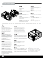
We recommend at this point to
start thinking about routing the cables
cleanly before connecting them to the
motherboard, cables include fan
cables, power supply 24pin cable,
CPU ATX 4pin/EPS12V 8pin, front
panel connectors, and front I/O
connectors.
An diesem Punkt empfehlen wir Ihnen,
über eine saubere Verlegung der Kabel
nachzudenken, bevor Sie die Kabel an das
Motherboard anschließen. Zu den Kabeln
zählen Stromversorgungskabel (24-polig),
CPU ATX-Kabel (4-polig)/EPS
12 V-Kabel(8-polig),
Frontblenden-Anschlusskabel sowie
Front-I/O-Kabel.
A ce stade nous recommandons de
commencer à organiser proprement les
câbles avant de les brancher à la carte
mère, câbles de ventilateurs, connecteur
24pin de l'alimentation, Connecteur
ATX 4 pin/EPS12V 8pin du processeur,
connecteurs du panneau frontal, et les
connecteurs des ports E/S frontaux
A questo punto, si raccomanda di pensare
a come gestire la disposizione dei cavi interni
prima di connetterli alla scheda madre. Si fa
riferimento ai i cavi delle ventole, all cavo
dell’alimentatore a 24 pin, al 4pin ATX ed
EPS 12V 8 pin, alle connessioni del pannello
frontale ed alle connessioni frontali I/O.
Le recomendamos que en este punto
comience a enrutar los cables con
limpieza antes de conectarlos a la placa
base. El término “cables” incluye los
cables de los ventiladores, el cable de
24 pines de la fuente de alimentación,
el de 4 pines CPU ATX/8 pines EPS12V,
conectores del panel frontal y conectores
de E/S frontales.
A questo punto, si raccomanda di
pensare a come gestire la disposizione
dei cavi interni prima di connetterli alla
scheda madre. Si fa riferimento ai i cavi
delle ventole, all cavo dell’alimentatore
a 24 pin, al 4pin ATX ed EPS 12V 8 pin,
alle connessioni del pannello frontale ed
alle connessioni frontali I/O.
이번 단계에서부터 케이블 정리에대해
생각해주시기를권장합니다.팬케이블, 파워
서플라이 24핀케이블, CPU,
ATX 4핀/EPS 12V 8pin, 전면패널 커넥터,
전면 IO 커넥터등이 대상이 됩니다.
建議您可以在這時開始理線,請先接上
ATX 24Pin、Front panel controller
與Front I/O各式線材。
建议您可以在这时开始理线,请先接上
ATX 24Pin、Front panel controller
与Front I/O各式线材。
マザーボードにケーブルを接続する前に、すっき
りしたケーブルの取り回しを考え始めるようお勧
めします。これには、ファンケーブル、電源24ピン
ケーブル、CPU ATX 4ピン/EPS12V 8ピン、フロン
トパネルコネクタ、およびフロントI/Oコネクタが含
まれます。
9.
10.

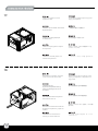
Install your slim optical drive onto
the bracket and secure with included
screws.
Установите тонкий оптический привод в
кронштейн и закрепите прилагаемыми
шурупами.
Installieren Sie Ihr dünnes optisches
Laufwerk in der Halterung und befestigen
Sie es mit den beiliegenden Schrauben.
Installez votre lecteur optique slim sur
le casier et fixez-le avec les vis incluses.
Instale su dispositivo óptico elgado
en el bracket y asegúrelo con los
tornillos incluidos.
Installare il lettore ottico slim nel
suo supporto e fissarlo con le viti
in dotazione.
슬림 광드라이브를 브라켓에 설치한 후
동봉된 나사로 고정시킵니다.
將薄型光碟機裝入光碟機架並以內附螺絲鎖固。
将薄型光驱装入光驱架并以内附螺丝锁固。
光学スリムドライブをブラケットに取り付け、
付属のネジで固定します。
Install your 2.5” hard drive onto the
optical drive bracket as shown and
secure with included screws.
(the maximum thickness of
2.5” hard drive is 15mm).
Установите ваш 2,5-дюймовый жесткий
диск в кронштейн оптического привода,
как показано на рисунке, и закрепите
прилагаемыми шурупами.
(Максимальная толщина 2,5-дюймового
жесткого диска - 15 мм.)
Installieren Sie Ihre 2,5 Zoll Festplatte in
der optischen Laufwerkshalterung wie
abgebildet und befestigen Sie sie mit den
beiliegenden Schrauben.
(Die maximale Höhe der 2,5 Zoll
Festplatte ist 15mm.)
Installez votre disque dur 2.5” sur le
casier du lecteur optique comme
montré et fixez-le avec les vis incluses.
(l’épaisseur maximum du disque dur
ne doit pas excéder 15mm).
Instale su disco duro de 2,5” en el
bracket para dispositivos ópticos
como se muestra y asegúrelo con
los tornillos incluidos (el grosor
máximo del disco duro de 2,5” es
de 15mm).
Installare l’hard disk da 2,5” sul
supporto del lettore ottico come
mostrato e fissarlo con le viti in
dotazione. (il massimo spessore
supportato per hard disk da 2,5”
è 15mm)
2.5” 하드 디스크를 그림에서와 같이
광드라이브 브라켓에 설치한 후 나사로
고정합니다. 2.5” 하드 드라이브의 최대
두께는 15mm 까지 설치 가능합니다.
依圖示將您的2.5”硬碟裝入光碟機架上並
以內附螺絲鎖固2.5吋硬碟的最大厚度為15mm
依图标将您的2.5”硬盘装入光驱架上并
以内附螺丝锁固2.5吋硬盘的最大厚度为15mm
図のように2.5”ハードディスクドライブを光学
ドライブブラケット上に取り付け、付属のネジ
で固定します。(2.5”ハードディスクドライブの
最大厚さは15mm)
8
11.
12.
La pagina sta caricando ...

We recommend connecting HDD
SATA connectors before installing
the graphics card
Мы рекомендуем подключать разъемы
жестких дисков SATA перед установкой
графической карты
Wir empfehlen, SATA-Festplattenstecker
vor der Installation der Grafikkarte
anzuschließen.
Nous recommandons de connecter les
connecteurs HDD SATA avant
d'installer les cartes graphiques
Le recomendamos enchufar los
conectores HDD SATA antes de
instalar la tarjeta gráfica
Si raccomanda di collegare i
connettori HDD SATA prima
di installare la scheda video
그래픽 카드를 설치할 때 HDD SATA 커넥터를
연결할 것을 권장합니다.
在安裝介面卡之前,建議先連接硬碟的SATA接線。
在安装适配卡之前,建议先连接硬盘的SATA接线。
グラフィックスカードのインストール前にHDD
SATAコネクタを接続するようお勧めします。
Please remove the screws holding
the expansion card slot cover,
and remove it.
Открутите шурупы на крышке слота карты
расширения и снимите крышку.
Please remove the screws holding the
expansion card slot cover,
and remove it.
Veuillez retirer les vis fixant les équerres
des emplacements d’extension, puis
retirez-les selon vos besoins.
Quite los tornillos que sujetan la
cubierta del zócalo de la tarjeta de
expansión y retírela.
Rimuovere le viti che che fissano la
mascherina dello slot delle schede di
espansione ed asportarlo.
확장슬롯 커버를 고정하고 있는 나사를
제거한 후 슬롯 커버를 제거합니다.
請將鎖固擴充槽檔片的螺絲卸下,
再將擴充槽檔片卸下。
请将锁固扩充槽档片的螺丝卸下,
再将扩充槽档片卸下。
拡張カードカバーを固定しているネジを外し、
カバーを取り外します。
10
15.
16.
La pagina sta caricando ...

After all cables and wirings are
connected, reinstall the top cover
and secure it.
Подключите все необходимые провода
и кабели, после чего поставьте на место
верхнюю крышку и закрепите ее
шурупами.
Nachdem alle Kabel und Drähte
verbunden sind, installieren und
befestigen Sie wieder die obere
Abdeckung.
Après avoir branché tous les câbles,
remettez le panneau supérieur et
f ixez-le.
Después de conectar todos los
cables, reinstale la cubierta
superior y fíjela.
Dopo aver conesso tutti i cavi,
reinstallare il pannello superior
e fissarlo.
모든 케이블과 선들이 연결되었으면 상부
커버를 재 설치한 후 나사로 고정시킵니다.
請在確認所有線材都已正確連接後裝回上蓋並
以螺絲鎖固.
请在确认所有线材都已正确连接后装回上盖并
以螺丝锁固.
全てのケーブルやリード線を接続してから、
上部カバーを元に戻してネジで固定します。
Attach the rubber standoff onto
the chassis appropriately as
required.
Прикрепите к корпусу резиновые опоры.
Befestigen Sie den Gummi-Abstandhalter
am Chassis wie benötigt
Collez les pieds en caoutchouc
convenablement sous le boîtier
comme exigé.
Enganche la base de goma en el
chasis si es necesario.
Applicare i piedini in gomma sul telaio.
고무 받침을 필요한만큼 케이스에 부착합니다.
依需求將橡膠腳墊適當地貼附於機殼上。
依需求将橡胶脚垫适当地贴附于机壳上。
必要に応じてケースにゴム製スタンドを
取り付けます。
12
19.
20.

13
Installation complete.
Установка завершена.
Die Installation ist vollständig.
Installation terminée.
Instalación completa.
Installazione completata.
설치가 완료되었습니다.
安裝完成。
安装完成。
インストール完了。
21.

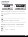
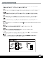
(1) Front panel connector installation
Power switch and reset switch installation guide:
Please refer to the motherboard manuals for the motherboard’s “Front Panel Connector” or “System Panel Connector” pin definition.
Power switch and reset switch have no polarity, so they can be connected in any orientation.
Bitte suchen Sie in der Motherboard-Dokumentation nach der Pinbelegung der Anschlüsse des Frontbedienfeldes („Front Panel Connectors“
oder „ System Panel Connectors“). Ein-/Austaste und Rücksetztaste benötigen keine bestimmte Polarität, können daher beliebig (ohne auf +
und - zu achten) angeschlossen werden.
Veuillez-vous référer au manuel de votre carte mère pour la description des broches "des connecteurs du panneau frontal" et des broches
"des connecteurs du panneau système". Les interrupteurs d'allumage et de réinitialisation ne possède pas de polarité, donc ils peuvent être
branché dans les deux sens.
Por favor, consulte en los manuales de la placa base la configuración de pines del “Conector de panel frontal” ó “Conector de panel de sistema”
de su placa base. Los interruptores de encendido y reseteo no tienen polaridad, luego se pueden conectar con cualquier orientación.
Fare riferimento al manuale della scheda madre nella sezione “Connettori del pannello frontale” o “Connettori del pannello di sistema”. Power
switch e reset switch non hanno polarità, posso essere pertanto connessi con qualsiasi orientamento.
Описание контактов разъемов приведены в разделах “Разъемы передней панели” или “Разъемы системной панели” руководства
пользователя материнской платы. Выключатель питания и кнопка перезагрузки не имеют полярности, поэтому их можно подключать
в любой ориентации.
請參考主機說明書的Front Panel Connectors安裝Pin Define,將Connector插上;Power Switch 與Reset Switch並無正負極性之分,
反插正插都不影響功能性。
请参考主机说明书的Front Panel Connectors安装Pin Define,将Connector插上;Power Switch 与Reset Switch并无正负极性之分,
反插正插都不影响功能性。
메인보드 매뉴얼의 전면패널 커넥터 혹은 시스템패널 커넥터 핀을 참조하기 바랍니다. 파워 스위치와 리셋 스위치는 극성이 없어 어떤
방향으로 설치해도 무방합니다.
マザーボードの「フロントパネルコネクタ」または「システムパネルコネクタ」のピン配列についてはマザーボードマニュアルを参照してください。
電源スイッチとリセットスイッチに極性はないので、いずれの方向でも接続できま。
14
Connector definition
La pagina sta caricando ...
La pagina sta caricando ...
La pagina sta caricando ...

18
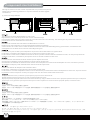
Component size limitations
(2) PSU limitation
SG05-Lite는 100mm 깊이의 표준 SFX 전원 공급장치를 지원합니다.
SG05-Liteは標準SFX電源(100㎜深)に対応しています。
The ST05-Lite supports standard SFX power supply with a 100mm depth.
Der SG05-Lite unterstützt SFX-Standardnetzteile mit einer Tiefe von 100 mm.
Le SG05-Lite supporte une source d'alimentation SFX standard avec une profondeur de 100mm.
La SG05-Lite acepta fuentes de alimentación SFX estándar con una profundidad de 100mm.
SG05-Lite supporta l’alimentatore standard SFX con una profondità di 100 mm.
SG05-Lite限定使用長度為100mm的標準SFX電源
SG05-Lite限定使用长度为100mm的标准SFX电源
Корпус SG05-Lite совместим со стандартными блоками питания SFX глубиной 100 мм.
La pagina sta caricando ...

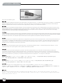
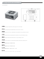
Component size limitations
(4) Optical drive limitation
SG05-Lite는 12.7mm 두께의 슬림형 광드라이브만 수용합니다.
아래는 두께가 12.7mm인 광드라이브의 예입니다.
SG05-Liteには、12.7mm厚スリム光学ドライブのみが装着可能です。
下図は、12.7mmの光学ドライブの例です。
SG05-Lite accommodates only 12.7mm thick slim optical drive
Below are examples of 12.7mm thick optical drives.
Корпус SG05-Lite допускает установку оптического привода толщиной только 12,7 мм
Ниже приведены примеры оптических приводов толщиной 12,7 мм
Das SG05-Lite nimmt ausschließlich 12,7 mm dünne optische Slim-Laufwerke auf.
Nachstehend finden Sie Beispiele zu optischen 12,7 mm-Laufwerken.
SG05-Lite loge seulement un disque optique mince de 12,7 mm d'épaisseur.
Nous vous présentons quelques exemples de disques optiques de 12,7 mm d'épaisseur ci-dessous.
La SG05-Lite acepta solo dispositivos ópticos de 12,7mm de grosor
A continuación hay ejemplos de dispositivos ópticos de 12,7mm de grosor
SG05-Lite accomoda unità ottiche slim di 12,7 mm di spessore
Di seguito sono riportati alcuni esempi di unità ottiche slim di 12,7 mm di spessore.
SG05-LITE只能使用12.7mm薄型光碟
以下是12.7mm光碟機範例供您做參考。
SG05-LITE只能使用12.7mm薄型光盘
以下是12.7mm光驱范例供您做参考。
20

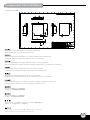
Upgrade and Maintenance
(1) Fan filter removal guide
SG05-Lite의 양압 디자인은 케이스 내부에 먼지가 싸이는 것을
방지 하기 위한 효과적인 디자인입니다. 작은 분진나이 먼지는
케이스 내부에 있는 필터에 시간에 따라 쌓이게 됩니다.
SG05-Lite의 우수한 냉각 성능을 계속 유지하기 위헤서 매 3개
월혹은 6개월(사용환경에 따라)마다 필터 청소를 권장합니다.
다음의 필터 제거 과정을 참고하세요.
SG05-Liteの正圧設計は、ケース内のホコリの蓄積を減少させる
有効な構造です。時と共に空気中の微粒子または糸くずはケース
内のコンポーネト上の代わりに取入れ口フィルタに溜まります。
この先何年もの間SG05-Liteの素晴らしい冷却性能を維持するには、
全てのファンを3ヶ月ないしは半年( 環境に依存) ごとに規則的に
清掃するようお勧めします。以下は、ファンフィルタを取り外す
手順です。
An example of a GPU cooler that is filled with dust and has lost most of its
cooling performance
SG05-Lite’s positive air pressure design is an effective configuration that
will reduce dust buildup inside the case. Small air particles or lint will
accumulate over time on intake filters instead of on the components inside
the case. To maintain SG05-Lite’s excellent cooling performance for years
to come, we recommend to clean all fan filters regularly every three months
or half a year (depending on your environment). Below are steps to remove
fan filters.
Конструкция корпуса SG05-Lite обеспечивает избыточное
давление воздуха и, таким образом, имеет эффективную
конфигурацию, препятствующую скоплению пыли внутри корпуса.
Небольшие частицы и волокна, содержащиеся в воздухе, со
временем будут скапливаться на впускных фильтрах, а не на
компонентах, находящихся внутри корпуса. Для поддержания
превосходного охлаждения компонентов в корпусе SG05-Lite в
течение многих лет рекомендуется регулярно очищать все
фильтры вентиляторов: раз в 3 месяца или раз в полгода
(в зависимости от условий окружающей среды). Ниже приведена
процедура для удаления фильтров вентиляторов.
Das vorteilhafte Luftdruckdesign des SG05-Lite ist eine effektive
Konfiguration, die Staubablagerungen innerhalb des Gehäuses vermindert.
Im Laufe der Zeit sammeln sich kleine Partikel und Fusseln an den
Luftzufuhrfiltern, anstatt an den Komponenten im Gehäuseinneren, an.
Sie können eine jahrelange optimale Kühlleistung des SG05-Lite
gewährleisten, indem Sie alle Lüfterfilter regelmäßig alle drei bis sechs
Monate reinigen (je nach Umgebungsbedingungen). Nachstehend finden
Sie die Schritte zur Entfernung der Lüfterfilter.
La conception à pression d'air positive du SG05-Lite est une configuration
efficace permettant de réduire l'accumulation de la poussière dans le boîtier.
De petites particules d'air ou de peluche vont s'accumuler avec le temps
sur les filtres d'aspiration, et non sur les composants à l'intérieur du boîtier.
Pour conserver les excellentes performances de refroidissement du
SG05-Lite au fil des ans, nous vous recommandons de nettoyer l'ensemble
des filtres des ventilateurs, tous les trois ou six mois (selon votre
environnement). Vous trouverez ci-dessous les étapes vous expliquant
comment retirer les filtres des ventilateurs.
El diseño de presión de aire positiva de la SG05-Lite es una configuración
efectiva que reducirá la acumulación de polvo dentro de la carcasa.
Pequeñas partículas de polvo ó pelusa se irán acumularán con el transcurso
del tiempo en los filtros de entrada en lugar de en los componentes
del interior de la carcasa. Para mantener la excelente capacidad de
refrigeración de la SG05-Lite en años venideros, le recomendamos que
limpie con regularidad todos los filtros de los ventiladores cada tres meses
ó seis meses (dependiendo de dónde viva). A continuación están los pasos
para quitar los filtros de los ventiladores.
Il design a pressione positiva di SG05-Lite riduce considerevolmente gli
accumuli di polvere all’interno del case. Le piccole particelle si accumulano
infatti sui filtri invece che sui componenti interni. Per mantenere le eccellenti
prestazioni di raffreddamento di SG05-Lite negli anni a venire vi
raccomandiamo di procedere ad una regolare pulizia dei filtri
(con cadenza trimestrale o semestrale dipendentemente dall’ambiente un
cui è disposto il sistema). Di seguito i passi per la rimozione dei filtri.
圖:被灰塵卡死的顯示卡散熱器
SG05-LITE的正壓差搭配濾網方式是經的起時間考驗最有效的防塵方
式。在使用相當長一段時間後,棉屑灰塵或其他可能妨礙散熱效能的
小異物只會卡在濾網,而不是電腦內的元件上面。我們重視的散熱效
能,是在您使用電腦長達2~3年後還能維持與全新的無異。為了維持這
種散熱效能您只需要定期清理濾網,而不是電腦裡面的元件。
視環境而定,我們建議您每6個月~1年必須清理濾網,以下是濾網與風扇
的拆卸步驟。
图:被灰尘卡死的显示卡散热器
SG05-LITE的正压差搭配滤网方式是经的起时间考验最有效的防尘方
式。在使用相当长一段时间后,棉屑灰尘或其它可能妨碍散热效能的
小异物只会卡在滤网,而不是计算机内的组件上面。我们重视的散热效
能,是在您使用计算机长达2~3年后还能维持与全新的无异。为了维持
这种散热效能您只需要定期清理滤网,而不是计算机里面的组件。
视环境而定,我们建议您每6个月~1年必须清理滤网,以下是滤网与风
扇的拆卸步骤。
21

Please remove the screws holding the
top cover with a screw driver, then pull
it toward the back to lift it outward away
from the chassis.
С помощью отвертки открутите
шурупы, удерживающие верхнюю
крышку, а затем снимите ее, сдвинув
назад и приподняв.
Bitte entfernen Sie die Schrauben der
oberen Abdeckung mit einem
Schraubenzieher und ziehen Sie die
Veuillez retirer les vis tenant le panneau
supérieur avec un tournevis, puis tirez-le
vers l’arrière afin de le soulever en dehors
du boîtier.
Por favor, quite los tornillos que sujetan
la cubierta superior con un destornillador,
luego tire de ella hacia atrás para quitarla
del chasis.
Rimuovere le viti del pannello superiore
con un cacciavite, spingerlo verso la parte
posteriore e sollevarlo per asportarlo
dal telaio.
상부 커버를 고정하고 있는 나사를
스크류 드라이버를 이용해 제거한 후,
뒤쪽으로 당겨 들어 올려, 케이스로
부터 제거합니다.
請以螺絲起子將鎖固上蓋的螺絲卸下,
並向後拉後提起以自機殼中取出。
請以螺絲起子將鎖固上蓋的螺絲卸下,
並向後拉後提起以自機殼中取出。
上部カバーを固定しているネジをドライバー
で外し、カバーを後方に引いてケースから
取り外します。
A.
Press the area as shown to release the
clips, then remove the front panel.
Нажмите на указанные зажимы и
снимите переднюю панель.
Drücken Sie auf die Stelle wie abgebildet, um
die Klemmen zu lösen und entfernen Sie die
Frontabdeckung.
Appuyez sur la zone comme montré pour
détacher les clips, puis retirez le panneau
frontal.
Presione la zona como se muestra para
soltar los enganches, luego quite el
panel frontal.
Premere nell’area indicata per sbloccare
i fermi, quindi rimuovere il pannello
frontale
그림에서와 같은 위치를 눌러 클립을
풀어준 후, 전면 패널을 제거합니다.
請依圖示輕按卡榫以卸下前面板。
请依图示轻按卡榫以卸下前面板。
図に示された場所を押してクリップを開放し、
フロントパネルを取り外します。
B.
Upgrade and Maintenance
22

Remove the fan filter
Снимите фильтр вентилятора.
Entfernen Sie den Lüfterfilter.
Enlever le filtre du ventilateur.
Retire el filtro del ventilador.
Rimuovere il filtro della ventola
팬 필터 분리
將濾網取下
将滤网取下
ファンフィルタの取り外し
C.
Loosen the 4 screws to remove the fan
from the inside of the case. Undo the
above steps to install the top cover.
Чтобы извлечь вентилятор из корпуса,
отверните 4 винта. Для установки
верхней крышки повторите описанные
выше операции в обратном порядке.
Lösen Sie die vier Schrauben zum Ausbauen
des Lüfters aus dem Gehäuse. Zur Installation
der oberen Abdeckung führen Sie die obigen
Schritte in umgekehrter Reihenfolge aus.
Devissez les 4 vis pour retirer le ventilateur
de l'intérieur du boîtier. Annulez les étapes
ci-dessus pour installer le couvercle
supérieur.
Afloje los 4 tornillos para retirar el
ventilador del interior de la carcasa.
Deshaga los pasos anteriores para
instalar la cubierta superior.
Allentare le 4 viti per rimuovere la
ventola dall'interno del case. Invertire la
precedente procedura per installare il
coperchio superiore.
4개의 나사를 풀고 팬을 케이스의
안쪽에서 분리합니다. 상기 단계를
반대로 실행하여 상단 커버를
설치합니다.
卸下風扇四顆鎖固螺絲,將風扇由機殼內
面取下, 接著以相反地順序將機殼裝回
卸下风扇四颗锁固螺丝,将风扇由机壳内
面取下, 接着以相反地顺序将机壳装回
ケース内部のネジ4本を外してファンを取り
外します。上部カバーを取り付けるには上
記ステップを逆順に行います。
D.
Upgrade and Maintenance
23
La pagina sta caricando ...
La pagina sta caricando ...
La pagina sta caricando ...
-
 1
1
-
 2
2
-
 3
3
-
 4
4
-
 5
5
-
 6
6
-
 7
7
-
 8
8
-
 9
9
-
 10
10
-
 11
11
-
 12
12
-
 13
13
-
 14
14
-
 15
15
-
 16
16
-
 17
17
-
 18
18
-
 19
19
-
 20
20
-
 21
21
-
 22
22
-
 23
23
-
 24
24
-
 25
25
-
 26
26
-
 27
27
-
 28
28


SilverStone SG05-LITE Manuale del proprietario
- Categoria
- Custodie per computer
- Tipo
- Manuale del proprietario
in altre lingue
- English: SilverStone SG05-LITE Owner's manual
- français: SilverStone SG05-LITE Le manuel du propriétaire
- español: SilverStone SG05-LITE El manual del propietario
- Deutsch: SilverStone SG05-LITE Bedienungsanleitung
- русский: SilverStone SG05-LITE Инструкция по применению
- 日本語: SilverStone SG05-LITE 取扱説明書
Documenti correlati
-
SilverStone SUGO SST-SG06S-LITE Manuale del proprietario
-
-
SilverStone Grandia GD09 Guida d'installazione
-
SilverStone ML06 Manuale del proprietario
-
-
-
-
-
-