
1
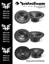
RFP3408/3808
RFP3410/3810
RFP3412/3812
RFP3415/3815
Installation
& Operation
Páginas de Referencia para la Instalación
Schéma d’Installation
Installations Beiblatt
Istruzioni di Installation

If, after reading your manual, you still have questions regarding this product, we
recommend that you see your Rockford Fosgate dealer. If you need further assis-
tance, you can call us direct at 1-800-669-9899. Be sure to have your serial num-
ber, model number and date of purchase available when you call.
The serial number can be found on the outside of the box. Please record it in the
space provided below as your permanent record. This will serve as verification of
your factory warranty and may become useful in recovering your speaker if it is ever
stolen.
Serial Number: __________________________________
Model Number:__________________________________
– i –
Sections marked
TROUBLESHOOTING
include recommendations for
curing installation problems
Sections marked
INSTALLATION
include “slam dunk”
wiring connections
Welcome to Rockford Fosgate! This manual is designed to provide informa-
tion for the owner, salesperson and installer. For those of you who want
quick information on how to install this product, please turn to the
Installation Section of this manual or refer to the icons listed below. Other
information can be located by using the Table of Contents. We, at Rockford
Fosgate, have worked very hard to make sure all the information in this
manual is current. But, as we are constantly finding new ways to improve
our product, this information is subject to change without notice.
GETTING STARTED
I
N
S
T
A
L
L
A
T
I
O
N
+ -
+ -
TROUBLE-
S
H
O
O
T
I
N
G
Visit our website for the latest information on all Rockford products.

Dear Customer,
C
ongratulations on your purchase of the world's finest brand of car audio
speakers. At Rockford Fosgate we are fanatics about musical reproduction
at its best, and we are pleased you chose our product. Through years of en-
gineering expertise, hand craftsmanship and critical testing procedures, we
have created a wide range of products that reproduce music with all the
clarity and richness you deserve.
For maximum performance we recommend you have your new Rockford
Fosgate product installed by an Authorized Rockford Fosgate Dealer, as we
provide specialized training through Rockford Technical Training Institute
(RTTI). Please read your warranty and retain your receipt and original car-
ton for possible future use.
Great product and competent installations are only a piece of the puzzle
when it comes to your system. Make sure that your installer is using 100%
authentic installation accessories from Connecting Punch in your installa-
tion. Connecting Punch has everything from RCA cables and speaker wire
to Power line and battery connectors. Insist on it! After all, your new system
deserves nothing but the best.
To add the finishing touch to your new Rockford Fosgate image order your
Rockford wearables, which include everything from T-shirts and jackets to
hats and sunglasses.
To get a free brochure on Rockford Fosgate products and Rockford wear-
ables, in the U.S. call 480-967-3565 or FAX 480-967-8132. For all other
countries, call +001-480-967-3565 or FAX +001-480-967-8132.
PRACTICE SAFE SOUND™
CONTINUOUS EXPOSURE TO SOUND PRESSURE LEVELS OVER 100dBMAY
CAUSE PERMANENT HEARING LOSS
. HIGH POWERED AUTOSOUND SYSTEMS
MAY PRODUCE SOUND PRESSURE LEVELS WELL OVER
130dB. USE COMMON
SENSE AND PRACTICE SAFE SOUND
.
– ii –

iii
Specifications
RFP3408 RFP3808 RFP3410 RFP3810 RFP3412 RFP3812 RFP3415 RFP3815
Fs (Hz) 41 40 32 34 28 29 24 23
Re (Ohms) 3.88 7.73 3.73 7.42 3.69 7.37 3.69 7.46
Le (mH) 3.63 6.14 4.42 7.38 4.48 7.48 4.64 7.53
Qts 0.478 0.529 0.447 0.507 0.472 0.533 0.537 0.554
Qes 0.517 0.588 0.481 0.554 0.510 0.584 0.581 0.608
Qms 6.234 5.273 6.255 5.919 6.237 6.085 7.215 6.190
Vas (Liters) 14.0 15.4 31.5 31.1 86.4 86.3 199.2 244.3
Vas (cuft) 0.49 0.54 1.11 1.10 3.05 3.05 7.04 8.63
SPL (db M/W) 84.9 84.4 85.4 85.7 87.6 87.6 89.1 89.1
XMAX (in) 0.31 0.31 0.51 0.51 0.51 0.51 0.51 0.51
XMAX (mm) 8 8 13 13 13 13 13 13
Power handling (RMS) 200 200 200 200 200 200 200 200
Power handling (Peak) 400 400 400 400 400 400 400 400
Speaker displacement 0.035 0.035 0.06 0.06 0.085 0.085 0.135 0.135
Sealed Box (cu. ft.) 0.3 0.3 0.75 0.75 1.25 1.25 2.5 2.5
Ported box (cu. ft.) 0.6250.62511222.52.5
Mounting diameter (in) 7-1/16 7-1/16 9-5/16 9-5/16 11-1/8 11-1/8 13-7/8 13-7/8
Mounting diameter (mm) 179 179 237 237 283 283 352 352
Mounting depth (in.) 3-13/16 3-13/16 5-3/8 5-3/8 5-13/16 5-13/16 7-3/16 7-3/16
Mountin
g
depth
(
mm
)
97 97 137 137 148 148 183 183

1
Table of Contents
Specifications........................................................................................................iii
Introduction ..........................................................................................................2
RF Punch HE Woofer Contents ..............................................................................2
Recommended Enclosures ....................................................................................2
Installation ............................................................................................................4
Recommended Enclosures ..............................................................................4
Building An Enclosure ....................................................................................6
Calculating Volume ........................................................................................6
Subwoofer Crossovers......................................................................................6
Wiring Configurations......................................................................................7
Warranty Information ............................................................................................8
International Information ......................................................................................9

2
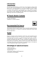
Introduction
The RF Punch HE Woofers are a full line of low frequency drivers sized
from 8" to 15" and are available in 4 or 8 ohm impedance. The RF Punch
HE woofers were designed for use primarily in small, sealed or ported
enclosures. By utilizing the latest materials and construction techniques,
we are able to offer a speaker with high output at low frequencies while
requiring a minimum of operating space.
RF Punch Woofer Contents
RF Punch HE Woofer
Installation & Owner's Manual
Recommended Enclosures
This manual outlines 2 specific types of enclosures that provide distinctly
different performance. This section is to help you decide which type is best
for your application.
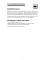
Sealed
Sealed enclosures are the simplest to build. The most important part of
building a sealed enclosure is to make sure that the enclosure is airtight.
Using glue and some type of sealant on all seams will ensure solid con-
struction and prevent air leaks. The box volume will directly impact the
performance of the speaker. Larger enclosure will provide flatter response
and deeper bass where smaller boxes will provide a bump in the response
curve and generally higher output for greater SPL.
Advantages of sealed enclosures
•Small enclosures
•Linear (Flat) response
•No port noise
•High power handling at all frequencies
•Excellent for sound quality
I
N
S
T
A
L
L
A
T
I
O
N
+ -
+ -

3
Recommended Enclosures
Vented Enclosures:
Vented enclosures vary only from the sealed enclosures in that a vent or
port is added to “tune” the enclosure. The enclosures recommended are
designed for great overall performance. Larger boxes tend to be easy to
tune to lower frequencies while medium and small boxes are easier to tune
to higher frequencies. The vented design is less linear in response than the
sealed box with noticeably more output at the tuning frequenc
y.
Advantages of vented enclosures
•Higher average output than sealed
•Tuning frequency can be easily adjusted by changing port length
•Deep bass response with lower power requirements
•Great for high output with limited power
I
N
S
T
A
L
L
A
T
I
O
N
+ -
+ -

4
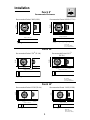
Recommended Enclosures
Punch 8"
Recommended Sealed .30ft
3
(8.50L)
D = 8"
(20.32cm)
H = 11"
(27.94cm)
W = 11"
(27.94cm)
Punch 10"
Recommended Sealed .75ft
3
(21.24L)
D = 10"
(25.40cm)
H = 14"
(35.56cm)
W = 15"
(38.10cm)
Punch 12"
Recommended Sealed 1.25ft
3
(35.40L)
D = 12"
(30.48cm)
H = 14"
(35.56cm)
W = 19-3/4"
(50.17cm)
D = 8"
(20.32cm)
H = 11"
(27.94cm)
W = 19.75"
(50.16cm)
Range in Cubic Feet
1 2 3 4 5 6
.50
.625
0.3
D = 13.5"
(34.29cm)
H = 13"
(33.02cm)
W = 15"
(38.1cm)
Range in Cubic Feet
1 2 3 4 5 6
0.3
.75
D = 14"
(35.56cm)
H = 18"
(45.72cm)
W = 20.5"
(52.07cm)
Range in Cubic Feet
1 2 3 4 5 6
0.3
1.50
Range in Cubic Feet
1 2 3 4 5 6
0.3
.50
1.50
Range in Cubic Feet
1 2 3 4 5 6
0.3
.625
1.50
.75
Range in Cubic Feet
1 2 3 4 5 6
0.3
1.25
1.75
Recommended Ported .625ft
3
(17.70L)
Recommended Ported 1.0 ft
3
(28.32L)
Recommended Ported 2.0 ft
3
(56.63L)
Fb = 40 Hz
Pd = 2.5" (6.35cm)
Pl = 11.25" (28.57cm)
Fb = 35 Hz
Pd = 3" (7.62cm)
Pl = 13.25" (33.65cm)
Fb=35 Hz
Pd=4" (10.16cm)
Pl=10.75" (27.30cm)
Installation
I
N
S
T
A
L
L
A
T
I
O
N
+ -
+ -

5
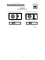
Punch 15"
Recommended Sealed 2.5ft
3
(70.79L)
D = 12"
(30.48cm)
H = 20"
(50.80cm)
W = 25"
(63.50cm)
Range in Cubic Feet
1 2 3 4 5 6
0.3
1.75
2.50
D = 12"
(44.45cm)
H = 20"
(43.18cm)
W = 25"
(48.26cm)
Range in Cubic Feet
1 2 3 4 5 6
0.3
7
5
5
0
Recommended Enclosures
Recommended Ported 2.5ft
3
(70.79L)
Fb = 35 Hz
Pd = 4" (10.16cm)
Pl = 8" (20.32cm)
Recommended Enclosures
I
N
S
T
A
L
L
A
T
I
O
N
+ -
+ -

6
Building an Enclosure
To work properly, the walls of the enclosure must be rigid and not flex
when subjected to the high pressures generated by the speaker's operation.
For optimum performance, we recommend using 3/4" MDF (Medium
Density Fiberboard) and internal bracing. The enclosure should be glued
together and secured with nails or screws. MDF is porous; therefore, it is
suggested to also seal the outside walls with polyurethane.
Calculating Volume
Calculating volume is merely a matter of measuring the dimensions in
inches and using the formula:
1728"/(cu in/cu ft)
Height” x Width” x Depth”
Box Volume=
(cubic feet)
If two facing sides are of uneven length, add them together and divide by
two to take the average. Using this number will give you the volume with-
out the necessity of calculating the box in sections and adding the sections
together. The thickness of the baffle material reduces the internal volume
so this must be subtracted from the outside dimensions to determine the
internal volume. The speaker itself also reduces the internal volume. The
amount of air displaced by each model is listed on the specification sheet
and should also be subtracted from the gross volume calculation.
Subwoofer Crossovers
There are two operational types of crossovers, passive and active. Passive
crossovers (coils or inductors) are placed on the speaker leads between the
amplifier and speaker. An active crossover is an electronic filter which sep-
arates the audio signal fed to different amplifiers.
For optimum subwoofer
performance, we recommend using an active 80-100Hz low-pass
crossover at 12dB/octave.

7
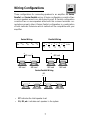
Wiring Configurations
Three configurations for connecting speakers to an amplifier are Series,
Parallel, and Series-Parallel wiring. A Series configuration consists of two
or more speakers wired in an string (end to end). A Parallel configuration
consists of two or more speakers wired with the common terminals con-
nected across each other. A Series-Parallel configuration is a combination
of both methods. Determine which method will be compatible with your
amplifier.
11111
=++++ etc.
R
T
R
1
R
2
R
3
R
4
Series Wiring
Parallel Wiring
+ –
+ –
+ –
+ –
4Ω
+ –
+ –
• R
T
indicates the total speaker load
•
R
1
, R
2
, etc. indicates each speaker in the system
Series-Parallel Wiring
I
N
S
T
A
L
L
A
T
I
O
N
+ -
+ -
R
T=
R
1+
R
2+
R
3+
R
4
4Ω load 4Ω load
+ – + –
+ –
8Ω load
8Ω load 8Ω load
+ – + –
+ –
4Ω load

8
Limited Warranty Information
Rockford Corporation offers a limited warranty on Rockford Fosgate products on the following terms:
• Length of Warranty
1 year on speakers 30 days on speaker B-stock (receipt required)
3 years on electronics 90 days on electronic B-stock (receipt required)
2 years on source units
•
What is Covered
This warranty applies only to Rockford Fosgate products sold to consumers by Authorized Rockford
Fosgate Dealers in the United States of America or its possessions. Product purchased by consumers
from an Authorized Rockford Fosgate Dealer in another country are covered only by that country’s
Distributor and not by Rockford Corporation.
• Who is Covered
This warranty covers only the original purchaser of Rockford product purchased from an Authorized
Rockford Fosgate Dealer in the United States. In order to receive service, the purchaser must provide
Rockford with a copy of the receipt stating the customer name, dealer name, product purchased and
date of purchase.
• Products found to be defective during the warranty period will be repaired or replaced (with a prod-
uct deemed to be equivalent) at Rockford's discretion.
• What is Not Covered
1. Damage caused by accident, abuse, improper operations, water, theft
2. Any cost or expense related to the removal or reinstallation of product
3. Service performed by anyone other than Rockford or an Authorized Rockford Fosgate Service Center
4. Any product which has had the serial number defaced, altered, or removed
5. Subsequent damage to other components
6. Any product purchased outside the U.S.
7. Any product not purchased from an Authorized Rockford Fosgate Dealer
• Limit on Implied Warranties
Any implied warranties including warranties of fitness for use and merchantability are limited in dura-
tion to the period of the express warranty set forth above. Some states do not allow limitations on the
length of an implied warranty, so this limitation may not apply. No person is authorized to assume for
Rockford Fosgate any other liability in connection with the sale of the product.
• How to Obtain Service
Please call 1-800-669-9899 for Rockford Customer Service. You must obtain an RA# (Return
Authorization number) to return any product to Rockford Fosgate. You are responsible for shipment of
product to Rockford.
Ship to:
Speakers
Rockford Acoustic Design
(Receiving-speakers)
609 Myrtle N.W.
Grand Rapids, MI 49504
RA#:_________________
Ship to:
Electronics
Rockford Corporation
Warranty Repair Department
2055 E. 5th Street
Tempe, AZ 85281
RA#:_________________

9
LEA DETENIDAMENTE LAS SIGUIENTES INSTRUCCIONES DE INSTA-
LACÍON DEL PRODUCTO.
Los terminales positivo y negativo de entrada están ubicados uno en cada
extremo de la carcasa. Este montaje separado previene de posibles corto-
circuitos de la señal a altos niveles de volumen. El terminal positivo está
marcado con un punto en la carcasa. Un punto rojo indica que la imped-
ancia del altavoz es de 8 ohmios, y un punto violeta que es de 4 ohmios.
Introduccíon
Los woofers RF Punch HE son una gama completa de drivers de baja fre-
cuéncia que comprenden diámetros de 8" a 15". Los Woofers RF Punch HE
fueron diseñados para su utilización en caja cerrada o bass-reflex mediana.
Diseñada para ofrecer la máxima calidad, los Woofers RF ofrecen al entu-
siasta principiante en sistemas de car audio, la oportunidad para disfrutar
de un bajo sólido en las bajas frecuéncias. Nuestros ingenieros han selec-
cionado materiales y técnicas para la construcción de nuestros altavoces
con el objetivo de ofrecer características y confianza comparable a otros
altavoces vendidos much más caros.
Terminales De Entrada
ESPAÑOL
Calculo Del Volumen
Para calcular el volumen sólo se han de medir las dimensiones en cen-
timetros y aplicar la fórmula:
Volumen du
la caja =
Si dos caras opuestas son de diferente tamaño, súmelas y divida el total por
dos para obtener el promedio. Usando esta técnica se ahorrara el cálculo
por secciones. El espesor del material con que está construida la caja
reduce el volumen interno, de manera quer ha de restarse de las dimen-
siones exteriores para determinar el volumen interior. La cantidad de aire
que ocupa cada modelo viene especificado en la hoja de caracteristicas y
también debe sustraerse para obtener el volumen neto interior.
1000cc
3
/litros
Alto (cm) x Ancho (cm) x Profundidad (cm)
(en litros)

10
Para un buen funcionamiento las paredes del recinto han de ser rigidas y
sin flexión a altas presiones de aire. Recomendamos usar un espesor de 1.9
cm de conglomerado de alta densidad o fibra de media densidad. Si el
recinto es muy grande es necessario reforzarlo internamente. Las juntas
deben ser encoladas y aseguradas con tornillos o grapas. Internamente las
juntas deben ser selladas con silicona para prevenir las fugas de aire. La
cola para madera es la mejor opción. Debido a la porosidad del conglom-
erado de alta densidad y la fibra es recomendable sellar exteriormente la
caja con poliuretano.
Construccion De Un Recinto
ESPAÑOL

11
VEUILLEZ LIRE LES INSTRUCTIONS SUIVANTES POUR L'INSTALLA-
TION DE CE PRODUIT.
Les bornes positives et négatives sont fixées de part et d'autre du saladier.
Cette séparation permet d'empêcher les courts-circuits entre les fils lors des
reproductions sonores élevées. La borne positive est repérée par un petit
point de couleur sur le saladier. Un point rouge est utilisé pour les haut-
parleurs de 8Ω, un point violet pour les haut-parleurs de 4Ω.
Introduction
Les woofers RF Punch HE sont une gamme complète de haut-parleurs de
graves allant de 20 à 46 cm et disponibles en 4Ω ou 8Ω.
Les woofer RF
Punch HE ont été conçus pour être utilisé de préférence en enceintes clos-
es.
En utilisant les techniques et les matériaux de construction les plus récents,
nous sommes parvenus à construire un haut-parleur fournissant un rende-
ment élevé dans les graves tout en requérant un volume opérationnel min-
imum.
BORNIERS
FRANÇAIS
Calcul Du Volume
On calcule le volume en mesurant la dimension de chaque côté et en util-
isant la formule suivante:
Volume du
caisson =
(Litres)
Si les due côtés qui se font face n'ont pas la même longueur, additionnez
les et divisez le résultat par deux pour obtenir la moyenne des deux
longueurs. Utilisez le nombre ainsi obtenu dans la formule pour détermin-
er le litrage. Cette méthode permet d'obtenir le volume du caisson sans
devoir faire de calculs compliqués de section de volume. L'épaisseur du
matériau dont est fait le caisson réduit le volume interne de celui-ci.
Lorsqu'on mesure les côtés du caisson il ne faut donc pas oublier d'oter des
mesures l'epaisseur du matériau. Le haut-parleur lui-même diminue le vol-
ume interne du caisson. Le volume d'air déplacé par chaque modèle de
haut-parleur est repris dans les spécifications techniques et doit également
être soustrait du volume total.
1000cc
3
/litres
Hauteur (cm) x Longueur (cm) x Largeur
(cm)

12
Pour fonctionner convenablement les parois du caisson doivent être rigides
lorsqu'elles sont soumises aux hautes pressions dues au fonctionnement du
haut-parleur. Nous vous recommandons d'utiliser des panneaux de bois
aggloméré à haute ou moyenne densité de particules de type “MDF”. Ces
panneaux sont disponibles dans la plupart des magasins de bricolage. Pour
un caisson de grand volume il est recommandé de placer des renforts à l'in-
térieur du caisson. Les différents côtés devront être collés (colle à bois) et
vissés (ou éventuellement cloués). Il est recommandé de mettre un joint de
silicone dans les arêtes internes du caisson afin d'éviter les fuites d'air. Du
fait de la porosité des matériaux que nous vous conseillons il est préférable
de recouvrir l'extérieur du caisson avec du polyuréthane.
Construire Un Caisson
FRANÇAIS

13
Anschlubterminals
BITTE LESEN SIE DIESE GEBRAUCHSANLEITUNG ZUERST SORGFÄLTIG
DURCH. DAS KANN SIE VOR FALSCHEM EINSATZ, AUSFALLEN ODER
SOGAR BESCHÄDIGUNG DES PRODUKTES ODER IHRES FAHRZEUGES
SCHÜTZEN.
Einleitung
Die RF-Punch HE Woofer sind eine komplette Produktlinie von Tief-
Frequenzlautsprechern mit Durchmesser von 20 cm bis zu 46 cm,
erhältlich in der Impendanz 4 - und 8 Ohm (Die RF Punch HE Woofer wur-
den vorwiegend fur den Einsatz in geschlossenen Gehäuse konstruiert).
Durch die Verwendung neuester Materialien und Produktionstechniken
können wir Ihnen heute einen Lautsprecher vorstellen, der hohe
Lautstärken und tiefe Frequenzen selbst in sehr kleinen Volumen repro-
duzieren kann.
Die Anschluβterminals wurden auf jeder Seite des Lautsprecherkorbes posi-
tioniert um eventuelle Kurzschlüsse auch bei hoher Leistung
auszuschlieβen (Das Positiv-Terminal ist durch eine Farbmarkierung geken-
zeichnet). Eine rote Farbamrkierung befindet sich immer bei einem
Lautsprecher mit einer Impedanz von 8 Ohm, eine violette Farbmarkierung
zeichnet die Lautsprecher mit der Impedanz 4 Ohm.
DEUTSCH
Volumen-Berechnung
Sollten zwei gegenüberliegende Seiten ungleich lang sein, so können sie
die Maβe zusammen rechnen und durch zwei dividieren um den
Durchschnitt zu erhalten. Dies macht Ihnen die Berechnung leichter und
Sie müssen das Gehäuse nicht in Sektionen berechnen, die Sie danach
wieder mühselig zusammen zählen müssen. Die Materialstärke beeinflu
βt
natürlich auch das Innen-Volumen, so muss für eine präzise Berechnung
die Materialstärke von Au
βen-Volumen abgezogen werden. Der
Lautsprecher verringert ebenfalls das Innen-Volumen, auch er sollte natür-
lich heraus gerechnet werden. Jedes Lautsprecher-Volumen ist unter
“Specifications” genau aufgelistet.
Gehäuse-
Volumen =
1000cc
3
/Kubik liter
Höhe (cm) x Breite (cm) x Tiefe (cm)
(Kubik Liter)
Zur Volumen-Berechung benötigen sie die genauen Maβe und
Dimensionen in Zentimetern.

14
Um das Gehäuse so präzise wie möglich zu bauen, sollten die
Gehäusewände sehr steif und luftundurchlässig sein, um dem entsehenden
Luftdruck des Lautsprechers standhalten zu können. Wir empfehlen 1,9 cm
mittelverdichtete Faserplatte (MDF), die in den meisten Baumärkten ange-
boten wird. Bei einem grö
βeren Gehäuse sollten Sie Versteifungen durch
Holzbalken montieren. Diese sollten – wie auch das gesamte Gehäuse –
mit Holzleim geklebt und verschraubt oder vernagelt sein. Um eine höhere
Dichte zu erreichen, empfiehlt es sich, die Kanten und Verschraubungen
mit Silikon abzudichten und das Gehäuse von innen mit einer
Hohlraumversiegelung zu behandeln.
Der Gehäuse Bau
DEUTSCH

15
LEGGERE CON ATTENZIONE LE SEGUENTI ISTRUZIONI PRIMA DEL-
L'INSTALLAZIONE DEL PRODOTTO.
I connettori di ingresso positivi e negativi sono montati sul cestello in
posizioni speculari. Il montaggio separato impedisce al segnale musicale di
cortocircuitarsi ad altissimi livelli di volume. (Il terminale di ingresso é indi-
cato da una marcatura colorata sul cestello.) Un contrassengno rosso indi-
ca che l'impedenza dell'altoparlante é 8 ohm, il contrassegno viola é imp-
iegato per i 4 ohm.
Introduzione
I woofer RF Punch HE sono una linea completa di altoparlanti per basse fre-
quenze con diametri che vanno da 20 a 46 cm e disponibili sia a 4 che a
8 ohm. (I woofer RF Punch HE sono progettati per il funzionamento princi-
pale in cassa chiusa.). Impiegando le piú aggiomate tecnologie e materiali,
siamo in grado di offrire altoparlanti che possono riprodurre un'elevata
pressione sonora alle basse frequenze mantenendo i volumi di impiego
assolutamente ridotti.
CONNESSIONI DI INGRESSO
ITALIANO
Calcolo del Volume
Calcolare il volume é essenzialmente solo un problema di misurazione
delle dimensioni in centimetri della cassa e di applicazione della formula:
Volume della
cassa =
(litri)
1000cc
3
/litri
Alteza (cm) x Larghezza (cm) x Profonditá (cm)
Se due pareti parallele sono di dimensioni diverse (prisma), semplicemente
sommatele e dividete il risulto per due. Impiegando il risultato ottenuto
potete calcolare il volume senza dividere la cassa i sezioni. Lo spessore del
legno riduce il volume interno, per cui é necessario sottrario dalle dimen-
sioni esterne. Anche il volume dell'altoparlante stesso riduce il volume
della cassa e deve essere sottratto. Il volume che ciascun altoparlante con-
tribuisce a togliere dalla cassa é indicato nelle tabelle con le specifiche.

16
Per ottenere le prestazioni massime, le pareti della cassa devono essere
rigide e non flettere sotto la sollecitaxione della elevata pressione generata
dal woofer. Noi raccomandiamo l'impiego di MDF con uno spessore min-
imo di 19 mm, materiale facilmente reperibile in tutte le falegnamerle. Per
casse di dimensioni molto grandi é indispensabile prevedere dei rinforzi
interni. Le giunture devono essere incollate e fissate con viti o chiodi in
abbondanza. Intermanmente le giunture devono essere siliconate per
impedire trafilati d'aria. Anche la colla da legno funziona bene. Essendo il
MDF un materiale poroso si consiglia di sigillare l'esterno con materiali
poliuretanici.
Costruire Una Cassa
ITALIANO
La pagina sta caricando ...
La pagina sta caricando ...
La pagina sta caricando ...
La pagina sta caricando ...
-
 1
1
-
 2
2
-
 3
3
-
 4
4
-
 5
5
-
 6
6
-
 7
7
-
 8
8
-
 9
9
-
 10
10
-
 11
11
-
 12
12
-
 13
13
-
 14
14
-
 15
15
-
 16
16
-
 17
17
-
 18
18
-
 19
19
-
 20
20
-
 21
21
-
 22
22
-
 23
23
-
 24
24


Rockford Fosgate Punch HE RFP3412 Installation & Operation Manual
- Tipo
- Installation & Operation Manual
- Questo manuale è adatto anche per
in altre lingue
- English: Rockford Fosgate Punch HE RFP3412
- español: Rockford Fosgate Punch HE RFP3412
Documenti correlati
-
 Rockford Fosgate RFR2215 Manuale utente
-
Rockford Fosgate RFD2110 Manuale utente
-
Rockford Fosgate RFP4406 Manuale utente
-
 Rockford Fosgate Marine Series Installation & Operation
-
 Rockford Fosgate RM112D2 Manuale utente
-
 Rockford Fosgate Prime R1S4-10 Installation & Operation
-
 Rockford Fosgate T112D2 Installation & Operation Manual
-
 Rockford Fosgate M1D4-12B Manuale utente
-
 Rockford Fosgate T1S1-12 Manuale del proprietario


