Brandt AD289XT1 Manuale del proprietario
- Tipo
- Manuale del proprietario

U
ser Guide - Glass hood
Le guide d’utilisation - Hotte Verre
Bedienungsanleitung -
Dunstabzugshaube aus Glas
Betjeningsvejledning - Emskærm med
glas for vægmontering
Användarmanual - Köksfläkt i glas
Bruksveiledning - Kjøkkenvifte
Libretto Istruzioni - Cappa Di Vetro
Manual de Utilização - Exaustor de Vidro
Ïäçãßåò ÷ñÞóçò
ãõÜëéíïõ áðïññïöçôÞñá êïõæßíáò
99625941_ML_A.qxd 18/11/02 13:47 Page 1

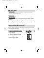
Contents
2
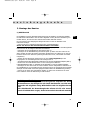
Introduction
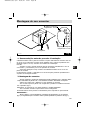
Dear Customer,
Thank you for choosing the BRANDT hood.
Our design staff have produced a new generation of kitchen equipment,
to make everyday cooking a pleasure.
The modern, attractive design of your new Brandt hood will blend
smoothly into your kitchen installation, providing an optimum combination
of easy use and performance.
The Brandt range also includes a huge choice of fitted cooking hobs,
ovens, dish-washers and refrigerators, that will match your new Brandt
hood.
Of course, we make every effort to ensure that our products meet all your
requirements, and our Customer Relations department is at your disposal,
to answer all your questions and to listen to all your suggestions (see
back cover of manual).
Brandt has always been a leader in the development of new products,
thus enhancing the quality of everyday life by providing increasingly effi-
cient products, that are easy to use, respect the environment, and are
attractive and reliable.
The BRANDT name.
Introduction P.2
Know the various parts of your hood P.3
Safety recommendations P.3
Installation conditions P.4
Installing your hood P.5-8
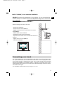
Connecting your hood P.9
Using your hood P.10
Changing a bulb P.10
Cleaning your hood P.11
How to contact us P.12
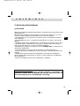
Throughout this manual,
indicates safety recommendations,
indicates advice to help you make the
best use of your duct
99625941_ML_A.qxd 18/11/02 13:47 Page 2

GB
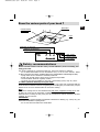
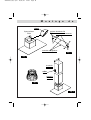
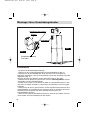
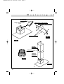
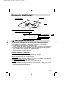
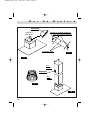
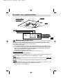
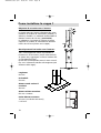
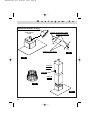
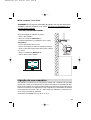
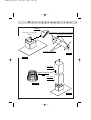
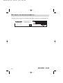
Know the various parts of your hood ?
Light
Metal filter
Control buttons
(see below)
123
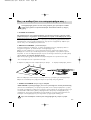
Safety recommendations
Lighting
Switching off the hood
Switching on the hood
Max. speed
Medium speed
Low speed
Please become familiar with the safety recommendations, before installing and
using your hood.
This hood is designed for normal household use. This hood contains no asbestos.
- Do not allow naked flames to burn beneath the duct, i.e. do not cook " flambé " dishes
or allow a gas ring to burn with no receptacle placed on it (extracted flames could damage the duct).
- Frying under the duct should be constantly monitored.
- Repair work should only be carried out by an approved specialist.
- The metal filters should be regularly cleaned .
- The hood must not be installed or used over a fuel burning (wood, coal, etc.) stove.
To obtain optimum efficiency from your hood:
- You should preferably use the rear cooking rings on your cooker. We recommend that the
hood should be switched on from the beginning of the cooking and, in certain cases, may be
allowed to run for a few minutes after the end of the cooking.
Note :
- When a cooking hood is used simultaneously with other equipment burning gas or simi-
lar fuels, the room must be adequately ventilated.
When the duct is running at max. power, the air in a kitchen is entirely evacuated, and thus
replaced, in a few minutes.
IMPORTANT
- In the case of a kitchen heated by equipment connected to a chimney (e.g. a stove, etc.), the
hood must be installed in recycling mode .
- Do not use the hood without the metal filters.
3
99625941_ML_A.qxd 18/11/02 13:47 Page 3

4
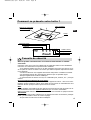
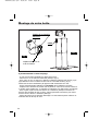
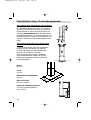
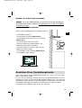
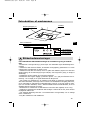
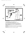
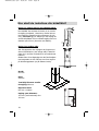
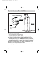
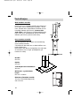
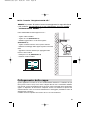
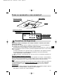
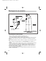
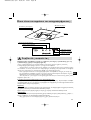
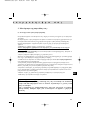
Installation conditions
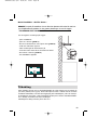
If you have an air outlet to outdoors:
Your hood can be connected to this outlet through an
evacuation duct (enamel finished, in aluminium, flexi-
hose or other non-inflammable material), with internal
diameter 150 mm (
not supplied
).
Otherwise, an adapter may be used to connect your
hood to an evacuation duct with internal diameter 125
mm (supplied with your hood).
If you have no air outlet to outdoors:
All our units can be used in recycling mode (
with no
outlet to outdoors
).
In this case, an active carbon filter should be instal-
led, to eliminate smells .
These filters are available from your Brandt retailer,
and the appropriate part number is shown on your
duct identification plate (see inside the hood).
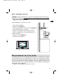
Width:
900 mm
Depth:
500 mm
Overall height under conduit:
280 mm
Min. - Max. height:
651 mm -1106mm
Outlet outer diameter:
150 mm (with non-return valve)
or 125 mm.
99625941_ML_A.qxd 18/11/02 13:47 Page 4

GB
5
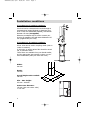
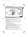
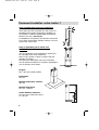
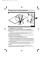
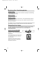
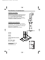
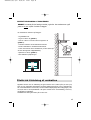
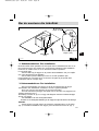
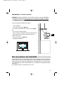
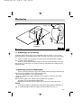
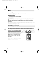
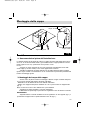
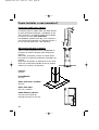
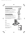
Installing your hood
fig. 1
A (hex. head,
length: 8 mm)
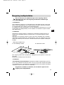
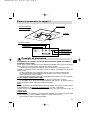
1. Pre-installation recommendations:
The distance between the cooking plane and the bottom of the hood must not be less
than 70 cm. If the instructions of the gas cooker installed under the hood specify a dis-
tance greater than 70 cm, then this distance must be respected.
Proceed as follows:
- Mark a vertical line on the wall, to ensure that your hood (and its chimney) are per-
fectly aligned with your cooker.
- Make a mark, on the vertical line, at least 70 cm above your cooking plane.
The vertical line and the mark at 70 cm will help you set up the installation as shown in
the attached installation diagram.
2. Installing the body of the hood:
- Place the installation diagram supplied against the wall, and align the vertical line
on the wall with the " hood centreline " shown on the diagram.
- Drill four holes, dia. 8 mm, as shown on the diagram.
- Mount the two supports on the wall, using the four screws and plugs supplied with
the duct (fig. 1).
Remark: In the case of a hollow wall, use the appropriate screws and plugs.
- Mount the hood by locating its rectangular holes on the supports.
The width of the holes is sufficient to allow some margin for left/right adjustment.
IMPORTANT :
- Adjust the height and levelling using the support adjustment screws " A " (fig.1),
and then mount the hood firmly against the wall by tightening the screws " B " (fig. 1).
B (Phillips head,
length: 25 mm)
rectangular holes
99625941_ML_A.qxd 18/11/02 13:47 Page 5

6
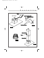
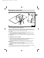
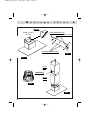
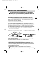
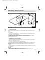
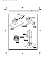
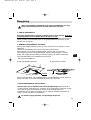
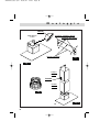
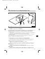
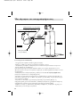
I n s t a l l i n
fig. 4
fig. 3
chimney mounting
chimney support plate
Pipe, internal
dia. 150 mm
triangular notches
inner chimney
outer chimney
fig. 2
fig. 5
vents
valve
99625941_ML_A.qxd 18/11/02 13:47 Page 6

GB
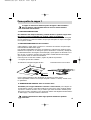
a) Operation with evacuation to outdoors
The installation must comply with applicable regulations concerning room ventilation.
In particular, evacuated air must not be transferred through a conduit used to evacuate
fumes from equipment burning gas or similar fuels.
Unused and existing conduits can only be used following approval by a qualified specialist.
- Remove the two mounting screws from the plastic deflector .
The plastic deflector is only used for an installation in recycling mode.
- Push the non-return valves (fig.2) into the hood outlet pipe. Remove the adhesive tape
retaining the valves.
- Recover the chimney support plate (fig.3).
- Mount the metal chimney support on the wall, in contact with the ceiling (fig.3).
Check that the two triangular notches are aligned with the vertical line on the wall (drill
dia. 8 mm, two screws and plugs supplied).
- Engage and secure the evacuation duct, dia. 150 mm (not supplied) in the hood outlet
pipe.
- In the case of a duct, dia. 125 mm, use the adapter supplied (fig.4).
- Prepare your telescopic chimney, carefully covering the vents (fig.5).
Push the chimney sections, one into the other, as far as possible.
- Mount the upper part of the inner chimney on the metal support, using the screws sup-
plied (to facilitate installation, pull the chimney slightly clear, so that the two returns can
be inserted behind the metal support).
- Adjust the length of the telescopic chimney, by lowering the outer part, and engaging it
in the opening in the glass.
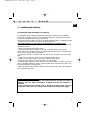
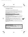
7
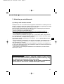
Installation recommendations:
For optimum use of your hood, we recommend that it be connected to a duct of
diameter 150 mm. Keep the number of angles and the duct length to a
minimum.
If your extractor hood is being used to dispel air outside, make sure your
kitchen has a fresh-air vent so that it does not become deprived of oxygen.
g y o u r hood
3. Installing the chimney:
99625941_ML_A.qxd 18/11/02 13:47 Page 7

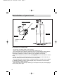
8
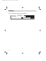
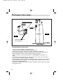
I
nstallation of your hood
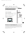
b) Operation in recycling mode
- In this case, non-return valves are not required .
- Remove the two mounting screws from the plastic deflector (fig. 6).
- Mount the plastic fumes deflector against the wall, in contact with the ceiling (drill two
holes, dia. 8 mm, 200 mm apart, and use the screws and plugs supplied) (fig. 6).
Check that the deflector is central, in relation to the vertical line on the wall.
- Mount the evacuation duct (dia. 150 mm,
not supplied
) between the deflector and the
hood.
- Prepare your chimney, ensuring that the vents are towards the top and visible (fig. 7).
Push the chimney sections one into the other, as far as possible.
- Mount the upper part of the chimney on the plastic deflector, using the screws supplied
(to facilitate installation, pull the chimney slightly clear, so that the two returns can be
inserted behind the plastic deflector).
- Adjust the length of the telescopic chimney, by lowering the outer part, and engaging it
in the opening in the glass.
position of screw and
plug
deflector
chimney mounting
fig. 7
fig. 6
vents
99625941_ML_A.qxd 18/11/02 13:48 Page 8

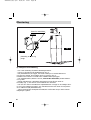
Connecting your hood
9
NOTE: "LE PLUS", for an attractive installation
BRANDT
cares about the appearance of your kitchen. You can now adjust the
hood to the tiles or credence. Ther
e is an adjustment margin of 10 mm in rela-
tion to the wal
l
“ AN EXCLUSIVE BRANDT FEATURE “.
Before mounting your hood on the wall:
- Remove the metal filter.
- Remove the two screws (item 1).
- Slightly unscrew the four screws, but do not remove
them (item 2).
- Pull the lower section outwards.
- Assemble and mount the hood as described .
- Adjust the lower section to be in contact with the tiles or
credence.
- Tighten the four screws (item 2).
- Install the metal filter.
Your hood is supplied with a power cable H05VVF, with three wires, section 0.75mm² (neu-
tral + phase and earth). Your hood should be connected to a 230 V single phase mains
power supply, through a standard power socket CEI 83, which should remain accessible
following the installation of the finishing panels, or through an omni-polar cutout, with a
contact opening gap of at least 3 mm. If the power cable is damaged, contact an authori-
sed Brandt service agent.
Your installation should include a fuse, rating 10 A or 16 A.
Détail d
tail d
écalage d
calage d
écor / mur
cor / mur
10 mm
GB
99625941_ML_A.qxd 18/11/02 13:48 Page 9

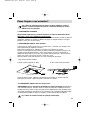
Changing a bulb
MODEL WITH HALOGEN LIGHTING
1. Remove the chrome trim " A " by tur-
ning it anti-clockwise.
2. Change halogen bulb " B ", type
GU10-50°-50W-230V by unscrewing it.
3. To restore the original configuration,
carry out the above operations in the
reverse sequence.
10
Before carrying out any work, switch off the hood either by unplugging the
power connector or by tripping the circuit breaker.
1/4
B
A
U
sing your hood
Low speed
:
- for simmering and dishes that create little
steam,
- to create ventilation in the kitchen.
Medium
speed:
- for normal cooking.
Maximum
speed:
- for cooking creating considerable fumes or steam (frying, pressure cooker).
Reset medium power immediately maximum power is no longer required.
We recommend that the hood be allowed to continue operating for a few minu-
tes after the end of the cooking, to ensure that the kitchen is properly ventila-
ted.
99625941_ML_A.qxd 18/11/02 13:48 Page 10

GB
Cleaning your hood
Handle
The hood should be switched off before the metal filters are removed.
After cleaning, the metal filters should be installed, as described in the
instructions.
1. ROUTINE MAINTENANCE
Never use metal cleaning pads, abrasive products or excessively hard brushes.
Do
not clean the stainless steel using ammonia-based products.
To clean the outer casing and the lighting window, use only household cleaning products,
diluted in water, rinse with clean water and wipe with a soft cloth.
2. MONTHLY MAINTENANCE: metal filter
The filter retains greasy vapours and dust, and is very important for the efficient opera-
tion of your hood.
It can progressively become inflammable, as it becomes saturated with greasy residue.
Clean the metal filter using commercial household cleaner, rinse thoroughly and dry.
In the dishwasher, this cleaning should be done using the filter only, in the vertical posi-
tion. Do not clean the filter at the same time as the dirty dishes because of the risk of
leaving stains.
Before using the metal filter for the first time, remove the protective film.
- To remove the metal filter:
1. Raise the filter handle. 2. Rotate the filter downwards.
After cleaning, install the filter by carrying out the above operations, in the reverse sequence.
The integral handle can be positioned to the left or to the right, as convenient.
3. ANNUAL MAINTENANCE: active carbon filter
ONLY for hoods operating in recycling mode (not connected to an evacuation to
outdoors). This filter retains smells and should be changed at least annually, as a func-
tion of utilisation and to avoid any risk of fire. Filters may be obtained from your Brandt
dealer (see part number shown on identification plate, inside the hood). Note the instal-
lation date of a new filter.
Before carrying out any work on the hood, check that it is
switched off.
11
99625941_ML_A.qxd 18/11/02 13:48 Page 11

12
In the spaces below, copy the reference numbers from your hood identification plate:
How to contact us
MADE IN FRANCE
230V ~ 50 Hz
BRANDT APPLIANCES SAS
7 rue Henri Becquerel
92500 RUEIL MALMAISON
99625941_ML_A.qxd 18/11/02 13:48 Page 12

13
99625941_ML_A.qxd 18/11/02 13:48 Page 13

Sommaire
Edito
Chère Cliente, Cher Client,
Vous venez d'acquérir une hotte BRANDT et nous vous en remercions.
Nos équipes de recherche ont conçu pour vous une nouvelle génération
d'appareils pour cuisiner chaque jour avec plaisir.
Avec des lignes pures et une esthétique moderne, votre nouvelle hotte
Brandt s'intègre harmonieusement dans votre cuisine et allie parfaite-
ment facilité d'utilisation et performances.
Vous trouverez également dans la gamme des produits Brandt, un vaste
choix de tables de cuisson, de fours, de lave-vaisselle et de réfrigérateurs
intégrables, que vous pourrez coordonner à votre nouvelle hotte Brandt.
Bien entendu, dans un souci permanent de satisfaire au mieux vos exi-
gences vis à vis de nos produits, notre service consommateurs est à votre
disposition et à votre écoute pour répondre à toutes vos questions ou
suggestions (coordonnées à la fin de ce livret).
A la pointe de l'innovation, Brandt contribue ainsi à l'amélioration de la
qualité de la vie quotidienne en vous apportant des produits toujours plus
performants, simples d'utilisation, respectueux de l'environnement, esthé-
tiques et fiables.
La Marque BRANDT.
Edito P.14
Comment se présente votre hotte ? P.15
Conseils de sécurité P.15
Comment installer votre hotte ? P.16
Montage de votre hotte P.17-20
Raccordement de votre hotte P.21
Utilisation de votre hotte P.22
Comment changer l’ampoule ? P.22
Comment nettoyer votre hotte ? P.23
Qui contacter ? P.24
Tout au long de la notice,
vous signale les consignes de sécurité,
vous signale les conseils et les astuces
14
99625941_ML_A.qxd 18/11/02 13:48 Page 14

FR
C
omment se présente votre hotte ?
Lampe
Filtre métallique
Boutons de commande
(voir ci dessous)
123
Conseils de sécurité
Eclairage
Arrêt hotte
Démarrage hotte
Grande vitesse
Moyenne vitesse
Petite vitesse
Merci de prendre connaissance de ces conseils avant d’installer et d’utiliser
votre hotte.
Cette hotte a été conçue pour être utlilisée par des particuliers dans leur lieu d’habitation.
Cette hotte ne contient aucun composant à base d’amiante.
- Il est interdit de flamber des mets ou de faire fonctionner des foyers gaz sans les recou-
vrir de plats de cuisson au-dessous de la hotte (les flammes aspirées risqueraient de dété-
riorer l’appareil).
- Les fritures effectuées sous l’appareil doivent faire l’objet d’une surveillance constante.
- Les réparations doivent être exclusivement effectuées par un spécialiste agréé.
- Nettoyez régulièrement les filtres métalliques .
- Le fonctionnement au-dessus d’un foyer à combustible (bois, charbon, etc...) n’est pas
autorisé.
Pour une meilleure efficacité de votre hotte
:
- Utilisez de préférence les foyers arrières de votre appareil de cuisson. - Nous vous recom-
mandons de faire fonctionner celle-ci dès le début de votre cuisson et éventuellement de la
maintenir allumée quelques minutes après la fin de la cuisson.
Nota :
-Une ventilation convenable de la pièce doit être prévue lorsqu’une hotte de cuisine est uti-
lisée simultanément avec des appareils utilisant du gaz ou un autre combustible.
Sachez qu’à grande vitesse le volume d’air d’une cuisine est renouvelé en quelques minutes.
IMPORTANT
- Dans le cas d’une cuisine chauffée avec un appareil raccordé à une cheminée (exemple:
poêle...), il faut installer la hotte en version recyclage.
- Ne pas utiliser la hotte sans les filtres métalliques.
15
99625941_ML_A.qxd 18/11/02 13:48 Page 15

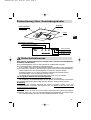
Comment installer votre hotte ?
Vous possédez une sortie vers l’extérieur
Votre hotte peut être raccordée sur celle-ci par l’in-
termédaire d’une gaine d’évacuation (émaillée, en
alu, flexible ou matière ininflammable de diamètre
intérieur 150 mm) (
non livrée
).
Un adaptateur vous permet de raccorder votre hotte
à une gaine d’évacuation diamètre intérieur 125 mm
(fourni avec votre hotte)
Vous ne possédez pas de sortie vers
l’extérieur :
Tous nos appareils ont la possibilité de fonctionner
en recyclage (
sans sortie extérieure
).
Dans ce cas, ajoutez un filtre à charbon actif qui
retiendra les odeurs .
Ces filtres sont disponibles chez votre revendeur
sous la référence indiquée sur la plaque signalétique
(voir à l’intérieur de la hotte).
Largeur :
600 - 900 mm suivant modèle.
Profondeur :
500 mm
Hauteur totale hors conduit :
280 mm
Hauteur mini-maxi :
651 mm -1106mm
Sortie diamètre extérieur :
150 mm (avec clapet anti-retour)
ou 125 mm.
16
99625941_ML_A.qxd 18/11/02 13:48 Page 16

FR
Montage de votre hotte
fig. 1
A (tête hexagonale
long : 8 mm)
1. R
ecommandations avant installation :
La distance minimale entre le plan de cuisson et la partie la plus basse de la hotte doit
être de 70cm. Si les instructions de la table gaz installée sous la hotte spécifient une dis-
tance plus grande que 70 cm, celle-ci doit être prise en compte.
Pour ce faire :
- Tracez un trait vertical sur le mur afin de positionner parfaitement l’axe de votre
hotte (et de sa cheminée) avec votre appareil de cuisson.
- Tracez un repère sur le trait vertical à 70 cm minimum de votre plan de cuisson.
Ce trait vertical et le repère à 70 cm vous aideront à positionner parfaitement le schéma
de montage joint.
2. M
ontage du corps de la hotte :
- Placez contre le mur le schéma de montage fourni avec l’appareil : alignez le trait
vertical du mur avec «l’axe central de la hotte» dessiné sur le schéma.
- Percez 4 trous diamètre 8, comme indiqué sur le schéma.
- Fixez les deux supports dans le mur à l’aide des 4 vis et chevilles fournies avec
l’appareil (fig. 1).
Remarque : dans le cas d’un mur creux, utilisez des vis et des chevilles adaptées.
- Accrochez la hotte par ses découpes rectangulaires.
La taille de ces découpes vous permet un réglage vers la gauche ou vers la droite.
IMPORTANT :
- Réglez la hauteur et le niveau en manoeuvrant les vis de réglage «A» des supports
(fig.1) puis bloquez la hotte contre le mur en serrant les vis «B» (fig. 1).
B (tête cruciforme
long : 25 mm)
découpes
rectangulaires
17
99625941_ML_A.qxd 18/11/02 13:48 Page 17

M ontage de
fig. 4
fig. 3
fixation de la cheminée
support cheminée tôle
Tuyau intérieur
∅150
encoches triangulaires
cheminée
intérieure
cheminée
extérieure
fig. 2
fig. 5
ouïes
clapet
18
99625941_ML_A.qxd 18/11/02 13:48 Page 18

a) Fonctionnement en évacuation extérieure
L’installation doit être conforme aux règlements en vigueur pour la ventilation des locaux.
En France, ces règlements sont indiqués dans le DTU 61.1 du CSTB. En particulier, l’air
évacué ne doit pas être envoyé dans un conduit utilisé pour évacuer les fumées d’appareils
utilisant du gaz ou un autre combustible.
L’utilisation de conduits désaffectés ne peut se faire qu’après accord d’un spécialiste com-
pétent.
- Enlevez les 2 vis de fixation du déflecteur plastique .
Cette pièce n’est utilisée que lors d’une installation en mode recyclage.
- Emboîtez les clapets anti-retours (fig.2) dans le tuyau de sortie de la hotte. Retirez le
ruban adhésif de maintien des clapets.
- Récupérez le support cheminée tôle (fig.3).
- Fixez contre le mur, en appui sur le plafond, le support de cheminée métallique (fig.3).
Prendre soin d’aligner les 2 encoches triangulaires du support métallique avec le trait verti-
cal sur le mur (perçage diamètre 8, 2 vis et chevilles fournies).
- Emboîtez et fixez la gaine d’évacuation diamètre 150 mm
(non livrée)
dans le tuyau de
sortie de la hotte.
- Dans le cas d’une gaine diamètre 125 mm, utilisez l’adaptateur fourni (fig.4)
- Préparez votre cheminée télescopique en prenant soin de dissimuler les ouïes (fig.5).
Emboîter les cheminées l’une dans l’autre au maximum.
- Fixez la partie supérieure de la cheminée intérieure sur le support métallique à l’aide des
vis fournies (afin de faciliter la mise en place, écartez légèrement la cheminée afin d’insé-
rer les deux retours derrière le support métallique).
- Ajustez la longueur de la cheminée télescopique en descendant la partie extérieure et
l’emboîter dans la découpe du verre.
Nos conseils d’installation :
pour une utilisation optimale de votre appareil, nous vous conseillons
le raccordement à une gaine diamètre 150 mm. Limiter au maximum le
nombre de coude et la longueur de la gaine.
Dans le cas où la hotte fonctionne en évacuation extérieure, il convient
d’assurer une arrivée d’air frais suffisante pour éviter de mettre la pièce
en dépression.
votre hotte
3. Montage de la cheminée:
19
FR
99625941_ML_A.qxd 18/11/02 13:48 Page 19

20
Montage de votre hotte
b) Fonctionnement en mode recyclage
- Il n’est pas nécessaire d’installer les clapets anti-retours .
- Enlevez les 2 vis de fixation du déflecteur plastique (fig. 6).
- Fixez contre le mur, en appui sur le plafond, le déflecteur plastique des fumées (2 per-
çages diamètre 8 avec un entraxe de 200 mm vis et chevilles fournies) (fig. 6).
Prendre soin de centrer le déflecteur par rapport au trait vertical tracé sur le mur.
- Fixez la gaine d’évacuation (diamètre 150
non livrée
) entre le déflecteur et la hotte.
- Préparez votre cheminée en prenant soin de placer les ouïes vers le haut de manière à
ce qu’elles soient visibles (fig. 7). Emboîter les cheminées l’une dans l’autre au maximum.
- Fixez la partie supérieure de la cheminée sur le déflecteur plastique à l’aide des vis
fournies (afin de facilier la mise en place, écartez légèrement la cheminée pour insérer
les deux retours derrière le déflecteur plastique).
- Ajustez la longueur de la cheminée télescopique en descendant la partie extérieure et
l’emboîter dans la découpe du verre.
emplacement de la vis
et de la cheville
déflecteur
fixation de la cheminée
fig. 7
fig. 6
ouïes
99625941_ML_A.qxd 18/11/02 13:48 Page 20
La pagina si sta caricando...
La pagina si sta caricando...
La pagina si sta caricando...
La pagina si sta caricando...
La pagina si sta caricando...
La pagina si sta caricando...
La pagina si sta caricando...
La pagina si sta caricando...
La pagina si sta caricando...
La pagina si sta caricando...
La pagina si sta caricando...
La pagina si sta caricando...
La pagina si sta caricando...
La pagina si sta caricando...
La pagina si sta caricando...
La pagina si sta caricando...
La pagina si sta caricando...
La pagina si sta caricando...
La pagina si sta caricando...
La pagina si sta caricando...
La pagina si sta caricando...
La pagina si sta caricando...
La pagina si sta caricando...
La pagina si sta caricando...
La pagina si sta caricando...
La pagina si sta caricando...
La pagina si sta caricando...
La pagina si sta caricando...
La pagina si sta caricando...
La pagina si sta caricando...
La pagina si sta caricando...
La pagina si sta caricando...
La pagina si sta caricando...
La pagina si sta caricando...
La pagina si sta caricando...
La pagina si sta caricando...
La pagina si sta caricando...
La pagina si sta caricando...
La pagina si sta caricando...
La pagina si sta caricando...
La pagina si sta caricando...
La pagina si sta caricando...
La pagina si sta caricando...
La pagina si sta caricando...
La pagina si sta caricando...
La pagina si sta caricando...
La pagina si sta caricando...
La pagina si sta caricando...
La pagina si sta caricando...
La pagina si sta caricando...
La pagina si sta caricando...
La pagina si sta caricando...
La pagina si sta caricando...
La pagina si sta caricando...
La pagina si sta caricando...
La pagina si sta caricando...
La pagina si sta caricando...
La pagina si sta caricando...
La pagina si sta caricando...
La pagina si sta caricando...
La pagina si sta caricando...
La pagina si sta caricando...
La pagina si sta caricando...
La pagina si sta caricando...
La pagina si sta caricando...
La pagina si sta caricando...
La pagina si sta caricando...
La pagina si sta caricando...
La pagina si sta caricando...
La pagina si sta caricando...
La pagina si sta caricando...
La pagina si sta caricando...
La pagina si sta caricando...
La pagina si sta caricando...
La pagina si sta caricando...
La pagina si sta caricando...
La pagina si sta caricando...
La pagina si sta caricando...
La pagina si sta caricando...
La pagina si sta caricando...
La pagina si sta caricando...
La pagina si sta caricando...
La pagina si sta caricando...
La pagina si sta caricando...
La pagina si sta caricando...
La pagina si sta caricando...
La pagina si sta caricando...
La pagina si sta caricando...
-
 1
1
-
 2
2
-
 3
3
-
 4
4
-
 5
5
-
 6
6
-
 7
7
-
 8
8
-
 9
9
-
 10
10
-
 11
11
-
 12
12
-
 13
13
-
 14
14
-
 15
15
-
 16
16
-
 17
17
-
 18
18
-
 19
19
-
 20
20
-
 21
21
-
 22
22
-
 23
23
-
 24
24
-
 25
25
-
 26
26
-
 27
27
-
 28
28
-
 29
29
-
 30
30
-
 31
31
-
 32
32
-
 33
33
-
 34
34
-
 35
35
-
 36
36
-
 37
37
-
 38
38
-
 39
39
-
 40
40
-
 41
41
-
 42
42
-
 43
43
-
 44
44
-
 45
45
-
 46
46
-
 47
47
-
 48
48
-
 49
49
-
 50
50
-
 51
51
-
 52
52
-
 53
53
-
 54
54
-
 55
55
-
 56
56
-
 57
57
-
 58
58
-
 59
59
-
 60
60
-
 61
61
-
 62
62
-
 63
63
-
 64
64
-
 65
65
-
 66
66
-
 67
67
-
 68
68
-
 69
69
-
 70
70
-
 71
71
-
 72
72
-
 73
73
-
 74
74
-
 75
75
-
 76
76
-
 77
77
-
 78
78
-
 79
79
-
 80
80
-
 81
81
-
 82
82
-
 83
83
-
 84
84
-
 85
85
-
 86
86
-
 87
87
-
 88
88
-
 89
89
-
 90
90
-
 91
91
-
 92
92
-
 93
93
-
 94
94
-
 95
95
-
 96
96
-
 97
97
-
 98
98
-
 99
99
-
 100
100
-
 101
101
-
 102
102
-
 103
103
-
 104
104
-
 105
105
-
 106
106
-
 107
107
-
 108
108


Brandt AD289XT1 Manuale del proprietario
- Tipo
- Manuale del proprietario
in altre lingue
- English: Brandt AD289XT1 Owner's manual
- français: Brandt AD289XT1 Le manuel du propriétaire
- Deutsch: Brandt AD289XT1 Bedienungsanleitung
- português: Brandt AD289XT1 Manual do proprietário
- dansk: Brandt AD289XT1 Brugervejledning
- svenska: Brandt AD289XT1 Bruksanvisning
Documenti correlati
Altri documenti
-
Groupe Brandt DHD159XP2 Manuale del proprietario
-
-
-
Groupe Brandt HM8699E1 Manuale del proprietario
-
-
Philips 68243100 Scheda dati
-
Massive 54444/30/10 Scheda dati
-
SVL 113440 Manuale del proprietario