
Guida rapida installatore - Installer quick guide
Guide rapide installateur - Guía rápida para el instalador
Kurzanleitung für den Installationstechniker - Σύντομος οδηγός τεχνικού εγκατάστασης
SW12.T
Centrale di comando 12 Vdc per cancelli battenti
12 Vdc control panel for swing gates
Centrale de commande 12 Vcc pour portails battants
Central de mando 12 Vcc para cancelas batientes
Steuergerät 12 Vdc für Drehtorantriebe
Κεντρική μονάδα ελέγχου 12 Vdc για ανοιγόμενες καγκελόπορτες
C
BAT
U
2
N8
F1 (ATO)
S
E
C
DIP1
FM1
FM2
VS
V
PWR
51
F2 (5X20)
F3.15 A
CNRX
U1
41
51
52
61
62
63
45
SW12.T
1
5
A
T1
T2
TCA
PROG
MRX
O
N
1
2
3
4
5
6
7
8
9
10
PRG
21
22
26
25
12
19
18
14
1
0
10
11
+E
-E
45
41
99
52
63
51
99
61
62
_
ANT

2
SW12.T
IT
Funzioni della morsettiera
Morsetto Descrizione Dati nominali
T1 Connessione secondario tarsformatore
12 Vac
T2 Connessione secondario tarsformatore
21 Apertura motore 1
12 Vdc 80 W
22 Chiusura motore 1
25 Apertura motore 2
12 Vdc 80 W
26 Chiusura motore 2
12
Negativo uscita radio ausiliaria/luce di
cortesia
12 Vdc 120 mA
1 Positivo accessori
19 Uscita elettroserratura
12 Vac 15 VA
18 Uscita elettroserratura
14 Negativo uscita spia cancello aperto
12 Vdc 120 mA
1 Positivo accessori
1 Positivo accessori
12 Vdc 300 mA
0 Negativo accessori
10 Negativo lampeggiante
12 Vdc 10 W max
11 Positivo lampeggiante
Morsetto Descrizione Dati nominali
+E Positivo alimentazione encoder
12 Vdc
-E Negativo alimentazione encoder
41 Segnale encoder motore 1
45 Segnale encoder motore 2
99 Comune ingressi
51 Passo-passo (N.O.)
52 Pedonale (N.O.)
99 Comune ingressi
61 Arresto (N.C.)
62 Fotocellula in chiusura (N.C.)
63 Fotocellula (N.C.)
- Massa antenna
ANT Segnale antenna
C
BAT
U
2
N8
F1 (ATO)
S
E
C
DIP1
FM1
FM2
VS
V
PWR
51
F2 (5X20)
F3.15 A
CNRX
U1
41
51
52
61
62
63
45
SW12.T
1
5
A
T1
T2
TCA
PROG
MRX
O
N
1
2
3
4
5
6
7
8
9
10
PRG
21
22
26
25
12
19
18
14
1
0
10
11
+E
-E
45
41
99
52
63
51
99
61
62
_
ANT
PED
P.P.
PHC
PH
STOP
COM
COM
M1
M2
OPEN M1
CLOSE M1
OPEN M2
CLOSE M2
LOCK
LOCK
RAU
RAU-
SCA-
SCA
12V+
12V-
BLINK-
BLINK+
ENC 12V-
ENC 12V+
ENC SIG A M1
ENC SIG A M2
230 Vac -
120 Vac -
N
L
12 Vdc
7 Ah max
+
P1
F1 (5X20)
T15 A
ECB5
+
12 Vdc
7 Ah max

1
SW12.T
IT
Attuatori comandabili
Cod. Descrizione
EIM1 - EA20 - EA20/SE Attuatore lineare 12 V 2 m
EA25 - EA25/SE Attuatore lineare 12 V 2,5 m
EA50 - EA50/SE Attuatore lineare 12 V 3,5 m
EI20 - EI20/SE - EI20/21 Attuatore interrato 12 V 2 m
ZI26 Attuatore interrato 12 V 2 m
ZI27 Attuatore interrato 12 V 3 m
Funzioni dei trimmer
Trimmer Descrizione
TCA Tempo di richiusura automatica (regolabile da 2 a 120 secondi, ruotare il trimmer in senso orario per aumentare il tempo)
FM1 Forza motore M1 (regola la coppia del motore M1, ruotare il trimmer in senso orario per aumentare la forza)
FM2 Forza motore M2 (regola la coppia del motore M2, ruotare il trimmer in senso orario per aumentare la forza)
VS Velocità di rallentamento (regola la velocità di rallentamento di entrambi i motori, ruotare il trimmer in senso orario per aumentare la velocità)
V Velocità standard (regola la velocità standard di entrambi i motori, ruotare il trimmer in senso orario per aumentare la velocità)
Funzioni dei tasti
Tasto Descrizione
PROG Tasto di programmazione della corsa
MRX Tasto di programmazione o cancellazione dei radiocomandi
51 Tasto di comando passo-passo
Funzioni dei Dip-switch
Dip Funzione Stato Descrizione
DIP 1 Chiusura
automatica
OFF Chiusura automatica non attiva
ON Chiusura automatica attiva
DIP 2 Condominiale
OFF
Condominiale attivo (durante l’apertura del cancello, non è possibile fermare il movimento con un comando radio o con
gli ingressi 51 (passo-passo) e 52 (pedonale). Con chiusura automatica attiva (DIP 1 = ON) e cancello aperto, un ulteriore
comando passo-passo (morsetto 51 o comando radio) rinnova il tempo di pausa e se l’ingresso 51 resta impegnato la
centrale sospende il conteggio della pausa no al disimpegno dell’ingresso (per il collegamento di eventuali spire o timer)
ON Condominiale non attivo
DIP 3 Prelampeggio
OFF Prelampeggio non attivo
ON Prelampeggio attivo, prima del movimento del cancello il lampeggiante si accende per 3 secondi
DIP 4 Tipo ingresso 63
OFF Ingresso 63 come fotocellula interna
ON Ingresso 63 come bordo sensibile (per tipo bordo sensibile vedere DIP 7)
DIP 5 Foto test
OFF Funzione foto test non attiva
ON
Funzione foto test attiva: il morsetto alimentazione accessori negativo (0) si spegne per qualche frazione di secondo
prima dell'inizio della manovra, eventuali accessori che necessitano di una alimentazione permanente (es. ricevitori
delle fotocellule) devono ricevere il negativo dell'alimentazione da un comune degli ingressi (morsetti 99).
DIP 6 Uscita 12
OFF
Uscita 12 come Luce di Cortesia (LCO): a ogni movimento del cancello l'uscita resta attiva per 100 s.
I tasti dei radiocomandi memorizzati sul secondo canale radio danno un comando pedonale
ON
Uscita 12 come uscita Radio Ausiliaria: i tasti dei radiocomandi memorizzati sul secondo canale radio attivano
l'uscita per 1 s
DIP 7
Tipo bordo
sensibile
OFF Bordo sensibile con contatto normalmente chiuso
ON Bordo sensibile resistivo, contatto normalmente aperto con resistenza di bilanciamento di 8,2 K Ohm in parallelo
DIP 8 Chiusura rapida
OFF Chiusura rapida non attiva
ON
Funzione di chiusura rapida attiva: l’intervento della fotocellula in chiusura (morsetto 62) porta il tempo di chiusura
automatica a 5 secondi, al suo disimpegno
DIP 9 Colpo d'ariete
OFF Funzione colpo d’ariete per elettroserratura non attiva
ON Funzione colpo d’ariete per elettroserratura attiva (facilita lo sgancio e il riarmo dell’elettroserratura)
DIP 10
Motore con/
senza encoder
OFF I motori collegati sono dotati di encoder
ON I motori collegati non sono dotati di encoder
Funzioni dei LED
LED Stato Descrizione
PWR
OFF Alimentazione di rete non presente
ON Alimentazione di rete presente
PRG
(o lampeggiante)
2 lampeggi Test fotocellule fallito (cablaggio errato o fotocellule occupate)
3 lampeggi Rilevato un problema sul circuito che attiva il motore M1
4 lampeggi Rilevato un problema sul circuito che attiva il motore M2
5 lampeggi Problema su encoder M1 (encoder M1 non funzionante o cablaggio encoder errato)
6 lampeggi Problema su encoder M2 (encoder M2 non funzionante o cablaggio encoder errato)
7 lampeggi Errore grave su EEPROM memoria EEPROM non presente o danneggiata)

2
SW12.T
IT
PRG
(o lampeggiante)
8 lampeggi Timeout motori (motoriduttore sbloccato o danneggiato)
9 lampeggi Fusibile F2 interrotto
10 lampeggi Errore sovracorrente motore M1
11 lampeggi Errore sovracorrente motore M2
41
OFF Quando il motore M1 è in funzione: segnale encoder assente (encoder non funzionante) o motore M1 senza encoder
ON
Quando il motore M1 è in funzione: segnale encoder presente (appare come un lampeggio molto rapido in funzione
della velocità di rotazione del motore)
45
OFF Quando il motore M2 è in funzione: segnale encoder assente (encoder non funzionante) o motore M2 senza encoder
ON
Quando il motore M2 è in funzione: segnale encoder presente (appare come un lampeggio molto rapido in funzione della
velocità di rotazione del motore)
51
OFF Ingresso passo-passo (mor. 51) non impegnato
ON Ingresso passo-passo (mor. 51) impegnato
52
OFF Ingresso pedonale (mor. 52) non impegnato
ON Ingresso pedonale (mor. 52) impegnato
61
OFF Contatto di arresto (mor. 61) aperto (impegnato)
ON Contatto di arresto (mor. 61) chiuso (non impegnato)
62
OFF Fotocellula in chiusura impegnata (mor. 62 aperto)
ON Fotocellula in chiusura non impegnata (mor. 62 chiuso)
63
OFF Fotocellula o bordo sensibile impegnata (mor. 63 aperto)
ON Fotocellula o bordo sensibile non impegnata (mor. 63 chiuso)
Taratura della corsa del cancello
NOTA: Per poter eseguire la taratura della corsa, il cancello deve essere fermo.
ATTENZIONE! DURANTE LA TARATURA DELLA CORSA DEL CANCELLO LE SICUREZZE SONO DISABILITATE.
Taratura rapida, motoriduttori con encoder (DIP 10 = OFF)
(rallentamenti al 30% della corsa, sfasamento in apertura 3 s, sfasamento in chiusura 6 s, la centrale apprende automaticamente in questa fase se sono
collegati 2 motori o uno solo)
N°
Pressione
pulsante
Fase Descrizione
1 PROG Attivazione procedura
Premere il pulsante di programmazione PROG per almeno 3 secondi no a quando il LED PRG
inizia a lampeggiare lentamente, rilasciare PROG.
2 51 Chiusura anta M2
Premere il pulsante 51:
M2 chiude a velocità rallentata no al fermo meccanico in chiusura
3 - Chiusura anta M1 M1 chiude a velocità rallentata no al fermo meccanico in chiusura
4 - Apertura anta M1 M1 apre a velocità rallentata no al fermo meccanico in apertura
5 - Apertura anta M2 M2 apre a velocità rallentata no al fermo meccanico in apertura
6 - Chiusura anta M2
M2 chiude a velocità normale, al 70% della corsa rallenta e continua no al fermo meccanico in
chiusura
7 - Chiusura anta M1
M1 chiude a velocità normale, al 70% della corsa rallenta e continua no al fermo meccanico in
chiusura
8 - Ciclo completo
Il cancello esegue un ciclo completo di apertura e di chiusura con gli spazi di rallentamento e con gli
sfasamenti di default.
9 - Fine procedura Il LED PRG si spegne. Procedura terminata.
Nota: con questo tipo di programmazione sono necessari i fermi meccanici sia in apertura che in chiusura sia durante la programmazione che nelle ma-
novre normali. Le fasi a sfondo grigio sono relative a un'installazione a doppia anta, che non vengono eseguite nel caso di installazione a anta singola.
Taratura avanzata, motoriduttori con encoder (DIP 10 = OFF)
(rallentamenti e sfasamenti programmati dall'installatore, la centrale apprende automaticamente in questa fase se sono collegati 2 motori o uno solo)
N°
Pressione
pulsante
Fase Descrizione
1 PROG Attivazione procedura
Premere e mantenere premuto il pulsante di programmazione PROG, il LED PRG inizia a lampeg-
giare lentamente, continuare a tenere premuto nchè il LED PRG lampeggia velocemente, rilasciare
PROG.
2 51 Chiusura anta M2
Premere il pulsante 51:
M2 chiude a velocità rallentata no al fermo meccanico in chiusura
3 - Chiusura anta M1 M1 chiude a velocità rallentata no al fermo meccanico in chiusura
4 - Apertura anta M1 M1 apre a velocità normale
5 51
Impostazione punto di
rallentamento in apertura M1
Premere 51 per ssare il punto di inizio rallentamento in apertura dell'anta M1
6 51
Impostazione punto di arresto
in apertura M1
Premere 51 per ssare il punto di completa apertura dell'anta M1 o attendere che l'anta arrivi al
fermo meccanico in apertura
7 - Apertura anta M2 M2 apre a velocità normale
8 51
Impostazione punto di
rallentamento in apertura M2
Premere 51 per ssare il punto di inizio rallentamento in apertura dell'anta M2
9 51
Impostazione punto di arresto
in apertura M2
Premere 51 per ssare il punto di completa apertura dell'anta M2 o attendere che l'anta arrivi al
fermo meccanico in apertura
10 - Chiusura anta M2 M2 chiude a velocità normale

3
SW12.T
IT
11 51
Impostazione punto di
rallentamento in chiusura M2
Premere 51 per ssare il punto di inizio rallentamento in chiusura dell'anta M2
12 - Completamento chiusura M2 L'anta M2 prosegue no al raggiungimento del fermo meccanico in chiusura
13 - Chiusura anta M1 M1 chiude a velocità normale
14 51
Impostazione punto di
rallentamento in chiusura M1
Premere 51 per ssare il punto di inizio rallentamento in chiusura dell'anta M1
15 - Completamento chiusura M1 L'anta M1 prosegue no al raggiungimento del fermo meccanico in chiusura
16 - Apertura anta M1 L'anta M1 riparte in apertura a velocità normale
17 51
Impostazione sfasamento in
apertura
Premere 51 per ssare il tempo di sfasamento in apertura
18 Completamento apertura M2 parte a velocità normale ed entrambe le ante arrivano a completa apertura
19 - Chiusura anta M2 L'anta M2 riparte in chiusura a velocità normale
20 51
Impostazione sfasamento in
chiusura
Premere 51 per ssare il tempo di sfasamento in chiusura
21 - Completamento chiusura M1 parte a velocità normale ed entrambe le ante arrivano a completa chiusura
22 - Fine procedura Il LED PRG si spegne. Procedura terminata.
Nota: con questo tipo di programmazione sono necessari i fermi meccanici in chiusura sia durante la programmazione che nelle manovre normali. Le fasi
a sfondo grigio sono relative a un'installazione a doppia anta, che non vengono eseguite nel caso di installazione a anta singola.
Taratura rapida, motoriduttori senza encoder (DIP 10 = ON)
(rallentamenti al 30% della corsa, sfasamento in apertura 3 s, sfasamento in chiusura 6 s, la centrale apprende automaticamente in questa fase se sono
collegati 2 motori o uno solo)
N°
Pressione
pulsante
Fase Descrizione
1 PROG Attivazione procedura
Premere il pulsante di programmazione PROG per almeno 3 secondi no a quando il LED PRG
inizia a lampeggiare lentamente, rilasciare PROG.
2 51 Chiusura anta M2
Premere il pulsante 51:
M2 chiude a velocità normale no al fermo meccanico in chiusura
3 - Chiusura anta M1 M1 chiude a velocità normale no al fermo meccanico in chiusura
4 - Apertura anta M1 M1 apre a velocità normale no al fermo meccanico in apertura
5 - Apertura anta M2 M2 apre a velocità normale no al fermo meccanico in apertura
6 - Chiusura anta M2 M2 chiude a velocità normale no al fermo meccanico in chiusura
7 - Chiusura anta M1 M1 chiude a velocità normale no al fermo meccanico in chiusura
8 - Ciclo completo
Il cancello esegue un ciclo completo di apertura e di chiusura con gli spazi di rallentamento e con gli
sfasamenti di default.
9 - Fine procedura Il LED PRG si spegne. Procedura terminata.
Nota: con questo tipo di programmazione sono necessari i fermi meccanici sia in apertura che in chiusura sia durante la programmazione che nelle ma-
novre normali. Le fasi a sfondo grigio sono relative a un'installazione a doppia anta, che non vengono eseguite nel caso di installazione a anta singola.
Taratura avanzata, motoriduttori senza encoder (DIP 10 = ON)
(rallentamenti e sfasamenti programmati dall'installatore, la centrale apprende automaticamente in questa fase se sono collegati 2 motori o uno solo)
N°
Pressione
pulsante
Fase Descrizione
1 PROG Attivazione procedura
Premere e mantenere premuto il pulsante di programmazione PROG, il LED PRG inizia a lampeg-
giare lentamente, continuare a tenere premuto nchè il LED PRG lampeggia velocemente, rilasciare
PROG.
2 51 Chiusura anta M2
Premere il pulsante 51:
M2 chiude a velocità normale no al fermo meccanico in chiusura
3 - Chiusura anta M1 M1 chiude a velocità normale no al fermo meccanico in chiusura
4 - Apertura anta M1 M1 apre a velocità normale
5 51
Impostazione punto di
rallentamento in apertura M1
Premere 51 per ssare il punto di inizio rallentamento in apertura dell'anta M1
6 - Completamento apertura M1 L'anta M1 prosegue no al fermo meccanico in apertura
7 - Apertura anta M2 M2 apre a velocità normale
8 51
Impostazione punto di
rallentamento in apertura M2
Premere 51 per ssare il punto di inizio rallentamento in apertura dell'anta M2
9 - Completamento apertura M2 L'anta M2 prosegue no al fermo meccanico in apertura
10 - Chiusura anta M2 M2 chiude a velocità normale
11 51
Impostazione punto di
rallentamento in chiusura M2
Premere 51 per ssare il punto di inizio rallentamento in chiusura dell'anta M2
12 - Completamento chiusura M2 L'anta M2 prosegue no al raggiungimento del fermo meccanico in chiusura
13 - Chiusura anta M1 M1 chiude a velocità normale
14 51
Impostazione punto di
rallentamento in chiusura M1
Premere 51 per ssare il punto di inizio rallentamento in chiusura dell'anta M1
15 - Completamento chiusura M1 L'anta M1 prosegue no al raggiungimento del fermo meccanico in chiusura
16 - Apertura anta M1 L'anta M1 riparte in apertura a velocità normale
17 51
Impostazione sfasamento in
apertura
Premere 51 per ssare il tempo di sfasamento in apertura

4
SW12.T
IT
18 Completamento apertura M2 parte a velocità normale ed entrambe le ante arrivano a completa apertura
19 - Chiusura anta M2 L'anta M2 riparte in chiusura a velocità normale
20 51
Impostazione sfasamento in
chiusura
Premere 51 per ssare il tempo di sfasamento in chiusura
21 - Completamento chiusura M1 parte a velocità normale ed entrambe le ante arrivano a completa chiusura
22 - Fine procedura Il LED PRG si spegne. Procedura terminata.
Nota: con questo tipo di programmazione sono necessari i fermi meccanici sia in apertura che in chiusura sia durante la programmazione che nelle ma-
novre normali. Le fasi a sfondo grigio sono relative a un'installazione a doppia anta, che non vengono eseguite nel caso di installazione a anta singola.
Programmazione dei radiocomandi
Nota: la programmazione dei radiocomandi è eseguibile solo ad automazione ferma
Programmazione del passo-passo
N. Pressione pulsante
Segnalazione
LED PRG
Descrizione
1 MRX Spento
Premere e mantenere premuto il pulsante MRX no a quando il LED PRG a luce verde inizia
a lampeggiare lentamente
2 Pulsante radiocomando Lampeggio lento Premere il tasto del radiocomando da memorizzare
3 -
Fisso 1 s Tasto del radiocomando memorizzato (nuovo radiocomando)
3 lampeggi Memoria piena
Programmazione del secondo canale radio
N. Pressione pulsante
Segnalazione
LED PRG
Descrizione
1 MRX Spento
Premere e mantenere premuto il pulsante MRX no a quando il LED PRG a luce verde inizia
a lampeggiare velocemente
2 Pulsante radiocomando Lampeggio veloce Premere il tasto del radiocomando da memorizzare
3 -
Fisso 1 s Tasto del radiocomando memorizzato (nuovo radiocomando)
3 lampeggi Memoria piena
Cancellazione di un radiocomando
N. Pressione pulsante
Segnalazione
LED PRG
Descrizione
1 MRX Spento
Premere e mantenere premuto il pulsante MRX no a quando il LED PRG a luce verde inizia
a lampeggiare molto velocemente
2 Pulsante radiocomando Lampeggio molto veloce Premere il pulsante del radiocomando da cancellare
3 - Fisso 1 s Cancellazione avvenuta
Cancellazione completa della ricevente
N. Pressione pulsante Segnalazione LED PRG Descrizione
1 - Spento Rimuovere l’alimentazione alla centrale, scollegare anche le batterie se presenti
2 MRX Acceso sso
Ridare alimentazione alla centrale senza rilasciare il tasto MRX no allo spegnimento del
LED PRG
3 - Spento Cancellazione completa della ricevente avvenuta
Nota: dopo la cancellazione di tutti i radiocomandi, il primo radiocomando memorizzato congura la centrale per accettare solo i radiocomandi
con codica rolling-code o solo radiocomandi con codica ssa.

5
SW12.T
Terminal block functions
Terminal Description Rated data
T1 Transformer secondary connection
12 Vac
T2 Transformer secondary connection
21 Opening motor 1
12 Vdc 80 W
22 Closing motor 1
25 Opening motor 2
12 Vdc 80 W
26 Closing motor 2
12
Auxiliary radio/courtesy light negative
output
12 Vdc 120 mA
1 Accessories positive
19 Electrical lock output
12 Vac 15 VA
18 Electrical lock output
14 Gate open warning light negative output
12 Vdc 120 mA
1 Accessories positive
1 Accessories positive
12 Vdc 300 mA
0 Accessories negative
10 Flashing light negative
12 Vdc 10 W max
11 Flashing light positive
Terminal Description Rated data
+E Encoder power supply positive
12 Vdc
-E Encoder power supply negative
41 Motor 1 encoder signal
45 Motor 2 encoder signal
99 Common inputs
51 Step by step (N.O.)
52 Pedestrian (N.O.)
99 Common inputs
61 Stop (N.C.)
62 Photocell when closing (N.C.)
63 Photocell (N.C.)
- Aerial earth
ANT Aerial signal
EN
C
BAT
U
2
N8
F1 (ATO)
S
E
C
DIP1
FM1
FM2
VS
V
PWR
51
F2 (5X20)
F3.15 A
CNRX
U1
41
51
52
61
62
63
45
SW12.T
1
5
A
T1
T2
TCA
PROG
MRX
O
N
1
2
3
4
5
6
7
8
9
10
PRG
21
22
26
25
12
19
18
14
1
0
10
11
+E
-E
45
41
99
52
63
51
99
61
62
_
ANT
PED
P.P.
PHC
PH
STOP
COM
COM
M1
M2
OPEN M1
CLOSE M1
OPEN M2
CLOSE M2
LOCK
LOCK
RAU
RAU-
SCA-
SCA
12V+
12V-
BLINK-
BLINK+
ENC 12V-
ENC 12V+
ENC SIG A M1
ENC SIG A M2
230 Vac -
120 Vac -
N
L
12 Vdc
7 Ah max
+
P1
F1 (5X20)
T15 A
ECB5
+
12 Vdc
7 Ah max

6
SW12.T
Controllable actuators
Ref. Description
EIM1 - EA20 - EA20/SE Linear operator 12 V 2 m
EA25 - EA25/SE Linear operator 12 V 2,5 m
EA50 - EA50/SE Linear operator 12 V 3,5 m
EI20 - EI20/SE - EI20/21 Underground operator 12 V 2 m
ZI26 Underground operator 12 V 2 m
ZI27 Underground operator 12 V 3 m
Trimmer function
Trimmer Description
TCA Automatic re-closing time (adjustable from 2 to 120 seconds, turn the trimmer clockwise to increase the time)
FM1 Power of motor M1 (adjusts the torque of motor M1, turn the trimmer clockwise to increase the force)
FM2 Power of motor M2 (adjusts the torque of motor M2, turn the trimmer clockwise to increase the force)
VS Slow speed (adjusts the slow speed of both motors, turn the trimmer clockwise to increase the speed)
V Standard speed (adjusts the standard speed of both motors, turn the trimmer clockwise to increase the speed)
Button functions
Button Description
PROG Button for programming the travel
MRX Button for programming or deleting remote controls
51 Step-by-step command button
DIP-switch functions
Dip Function Status Description
DIP 1
Automatic
closing
OFF Automatic closing o
ON Automatic closing on
DIP 2
Apartment
block
OFF
Apartment block on (while the gate is opening, you cannot stop the movement with a radio command or with inputs
51 (step-by-step) and 52 (pedestrian). With automatic closing on (DIP 1 = ON) and the gate open, an additional
step-by-step command (terminal 51 or radio command) renews the pause time, and if input 51 remains engaged,
the control panel suspends the pause count until the input is disengaged (for connecting any coils or a timer)
ON Apartment block o
DIP 3 Pre-ash
OFF Pre-ashing o
ON Pre-ashing on, before the gate moves the ashing light comes on for 3 seconds
DIP 4 Input 63 type
OFF Input 63 is for internal photocell
ON Input 63 is for safety edge (see DIP 7 for the safety edge type)
DIP 5 Photo test
OFF Photo-test function o
ON
Photo-test on: the negative accessory power supply terminal (0) turns o for a few fractions of a second before the
start of movement, so any accessories that require a permanent power supply (e.g. photocell receivers) must get
the negative power supply from an input common (terminal 99).
DIP 6 Output 12
OFF
Output 12 for Courtesy Light (LCO): each time the gate moves, the output remains on for 100 s.
The remote control buttons saved on the second radio channel give a pedestrian command
ON Output 12 for Auxiliary Radio output: the remote control buttons saved on the second radio channel turn the output on for 1 s
DIP 7
Safety edge
type
OFF Sensitive edge with normally closed contact
ON Resistive sensitive edge, normally open contact with balancing resistance of 8.2 K Ohm in parallel
DIP 8 Rapid closing
OFF Fast closing o
ON
Fast closing function on: if the closing photocell (terminal 62) is engaged, the automatic closing time is set to 5
seconds when it is released
DIP 9 Hammering
OFF Hammering function for electric lock o
ON Hammering function for electric lock on (facilitates the unlocking and resetting the electric lock)
DIP 10
Motor with/
without encoder
OFF The motors connected are equipped with encoders
ON The motors connected are not equipped with encoders
LED functions
LED Status Description
PWR
OFF Mains power supply not present
ON Mains power supply present
PRG
(or ashing light)
2 blinks Photocell test failed (incorrect wiring or photocells busy)
3 blinks Problem detected in the circuit that activates motor M1
4 blinks Problem detected in the circuit that activates motor M2
5 blinks Problem on encoder M1 (encoder M1 damaged or wired incorrectly)
6 blinks Problem on encoder M2 (encoder M2 damaged or wired incorrectly)
7 blinks Serious EEPROM error (EEPROM missing or damaged)
EN

7
SW12.T
PRG
(or ashing light)
8 blinks Motor timeout (gear motor not engaged or damaged)
9 blinks Fuse F2 blown
10 blinks Motor M1 overcurrent error
11 blinks Motor M2 overcurrent error
41
OFF When motor M1 is operating: it indicates that the encoder is missing (not working) or motor M1 has no encoder
ON
When motor M1 is operating: it indicates that there is an encoder (it ashes very fast, depending on the motor rota-
tion speed)
45
OFF When motor M2 is operating: it indicates that the encoder is missing (not working) or motor M2 has no encoder
ON
When motor M2 is operating: it indicates that there is an encoder (it ashes very fast, depending on the motor rotation
speed)
51
OFF Step-by-step input (term. 51) not engaged
ON Step-by-step input (term. 51) engaged
52
OFF Pedestrian input (term. 52) not engaged
ON Pedestrian input (term. 52) engaged
61
OFF Stop contact (term. 61) open (engaged)
ON Stop contact (term. 61) closed (not engaged)
62
OFF Closing photocell (term. 62) engaged
ON Closing photocell (term. 62) not engaged
63
OFF Photocell or safety edge (term. 63) open (engaged)
ON Photocell or safety edge (term. 63) closed (not engaged)
Gate travel calibration
NOTE: To perform this procedure, the gate must be stationary.
WARNING! THE SAFETY DEVICES ARE DISABLED DURING GATE TRAVEL CALIBRATION.
Fast calibration, gear motor with encoder (DIP 10 = OFF)
(slows down at 30% of its travel, opening oset of 3 s, closing oset of 6 s, in this phase the control unit automatically learns whether 2 motors are con-
nected or just one)
No.
Pressing
push button
Phase Description
1 PROG Procedure activation
Press the programming push-button PROG for at least 3 seconds, until the PRG LED starts ash-
ing slowly, and then release it
2 51 Close leaf M2
Press push-button 51:
M2 closes at slow speed until it reaches the closed mechanical stop
3 - Close leaf M1 M1 closes at slow speed until it reaches the closed mechanical stop
4 - Open leaf M1 M1 closes at slow speed until it reaches the open mechanical stop
5 - Open leaf M2 M2 closes at slow speed until it reaches the open mechanical stop
6 - Close leaf M2
M2 closes at normal speed, slows down at 70% of its travel, and continues until it reaches the
closed mechanical stop
7 - Close leaf M1
M1 closes at normal speed, slows down at 70% of its travel, and continues until it reaches the
closed mechanical stop
8 - Complete cycle
The gate performs a complete opening and closing cycle with the default slow-down distance and
osets.
9 - End of procedure The PRG LED turns o. End of procedure
Note: With this type of programming, the mechanical stops are necessary both when opening and closing, during programming and in normal operation.
The steps with a grey background are for a double-leaf installation, and are not carried out for a single-leaf installation.
Advanced calibration, gear motor with encoder (DIP 10 = OFF)
(slow-down and osets programmed by the installer, in this phase the control unit automatically learns whether 2 motors are connected or just one)
No.
Pressing
push button
Phase Description
1 PROG Procedure activation
Press the programming push-button PROG and hold it down; the PRG LED will start ashing
slowly; keep PROG pressed until the PRG LED ashes fast, and then release it
2 51 Close leaf M2
Press push-button 51:
M2 closes at slow speed until it reaches the closed mechanical stop
3 - Close leaf M1 M1 closes at slow speed until it reaches the closed mechanical stop
4 - Open leaf M1 M1 opens at normal speed
5 51
Set the slow-down point when
opening M1
Press 51 to set the slow-down start point when opening leaf M1
6 51
Set the stopping point when
opening M1
Press 51 to set the fully-open point of leaf M1, or wait for the leaf to reach the open mechanical
stop
7 - Open leaf M2 M2 opens at normal speed
8 51
Set the slow-down point when
opening M2
Press 51 to set the slow-down start point when opening leaf M2
9 51
Set the stopping point when
opening M2
Press 51 to set the fully-open point of leaf M2, or wait for the leaf to reach the open mechanical
stop
10 - Close leaf M2 M2 closes at normal speed
11 51
Set the slow-down point when
closing M2
Press 51 to set the slow-down start point when closing leaf M2
EN

8
SW12.T
12 - Complete M2 closure Leaf M2 continues until it reaches the closed mechanical stop
13 - Close leaf M1 M1 closes at normal speed
14 51
Set the slow-down point when
closing M1
Press 51 to set the slow-down start point when closing leaf M1
15 - Complete M1 closure Leaf M1 continues until it reaches the closed mechanical stop
16 - Open leaf M1 Leaf M1 restarts opening at normal speed
17 51 Setting the oset for opening Press 51 to set the opening oset time
18 Completion of opening M2 starts at normal speed and both leaves open fully
19 - Close leaf M2 Leaf M2 restarts closing at normal speed
20 51 Setting the oset for closing Press 51 to set the closing oset time
21 - Complete closure M1 starts at normal speed and both leaves close fully
22 - End of procedure The PRG LED turns o. End of procedure
Note: With this type of programming, the mechanical stops are necessary both when closing during programming and in normal operation. The steps with
a grey background are for a double-leaf installation, and are not carried out for a single-leaf installation.
Fast calibration, gear motor without encoder (DIP 10 = ON)
(slows down at 30% of its travel, opening oset of 3 s, closing oset of 6 s, in this phase the control unit automatically learns whether 2 motors are con-
nected or just one)
No.
Pressing
push button
Phase Description
1 PROG Procedure activation
Press the programming push-button PROG for at least 3 seconds, until the PRG LED starts ash-
ing slowly, and then release it
2 51 Close leaf M2
Press push-button 51:
M2 closes at normal speed up to the closed mechanical stop
3 - Close leaf M1 M1 closes at normal speed up to the closed mechanical stop
4 - Open leaf M1 M1 opens at normal speed until it reaches the open mechanical stop
5 - Open leaf M2 M2 opens at normal speed until it reaches the open mechanical stop
6 - Close leaf M2 M2 closes at normal speed up to the closed mechanical stop
7 - Close leaf M1 M1 closes at normal speed up to the closed mechanical stop
8 - Complete cycle
The gate performs a complete opening and closing cycle with the default slow-down distance and
osets
9 - End of procedure The PRG LED turns o. End of procedure
Note: With this type of programming, the mechanical stops are necessary both when opening and closing, during programming and in normal operation.
The steps with a grey background are for a double-leaf installation, and are not carried out for a single-leaf installation.
Advanced calibration, gear motor without encoder (DIP 10 = ON)
(slow-down and osets programmed by the installer, in this phase the control unit automatically learns whether 2 motors are connected or just one)
No.
Pressing
push button
Phase Description
1 PROG Procedure activation
Press the programming push-button PROG and hold it down; the PRG LED will start ashing
slowly; keep PROG pressed until the PRG LED ashes fast, and then release it
2 51 Close leaf M2
Press push-button 51:
M2 closes at normal speed up to the closed mechanical stop
3 - Close leaf M1 M1 closes at normal speed up to the closed mechanical stop
4 - Open leaf M1 M1 opens at normal speed
5 51
Set the slow-down point when
opening M1
Press 51 to set the slow-down start point when opening leaf M1
6 - Complete M1 opening Leaf M1 continues to the closed mechanical stop
7 - Open leaf M2 M2 opens at normal speed
8 51
Set the slow-down point when
opening M2
Press 51 to set the slow-down start point when opening leaf M2
9 - Complete M2 opening Leaf M2 continues to the closed mechanical stop
10 - Close leaf M2 M2 closes at normal speed
11 51
Set the slow-down point when
closing M2
Press 51 to set the slow-down start point when closing leaf M2
12 - Complete M2 closure Leaf M2 continues until it reaches the closed mechanical stop
13 - Close leaf M1 M1 closes at normal speed
14 51
Set the slow-down point when
closing M1
Press 51 to set the slow-down start point when closing leaf M1
15 - Complete M1 closure Leaf M1 continues until it reaches the closed mechanical stop
16 - Open leaf M1 Leaf M1 restarts opening at normal speed
17 51 Setting the oset for opening Press 51 to set the opening oset time
18 Completion of opening M2 starts at normal speed and both leaves open fully
19 - Close leaf M2 Leaf M2 restarts closing at normal speed
20 51 Setting the oset for closing Press 51 to set the closing oset time
21 - Complete closure M1 starts at normal speed and both leaves close fully
22 - End of procedure The PRG LED turns o. End of procedure
EN

9
SW12.T
Note: With this type of programming, the mechanical stops are necessary both when opening and closing, during programming and in normal operation.
The steps with a grey background are for a double-leaf installation, and are not carried out for a single-leaf installation.
Remote control programming
Note: remote control programming can only be done with the automatic gate system stationary
Step-by-step programming
No. Pressing push button Signal PRG LED Description
1 MRX O Press the MRX push-button and hold it down until the green PRG LED starts ashing slowly
2
Remote control push-
button
Slow blink Press the remote control push-button that you want to save
3 -
Fixed 1 s Button of the saved remote control (new remote control)
3 blinks Memory full
Programming the second radio channel
No. Pressing push button Signal PRG LED Description
1 MRX O Press the MRX push-button and hold it down until the green PRG LED starts ashing fast
2
Remote control push-
button
Fast blink Press the remote control push-button that you want to save
3 -
Fixed 1 s Button of the saved remote control (new remote control)
3 blinks Memory full
Deleting a remote control
No. Pressing push button Signal PRG LED Description
1 MRX O
Press the MRX push-button and hold it down until the green PRG LED starts ashing very
fast
2
Remote control push-
button
Very fast ashing Press the button on the remote control to delete
3 - Fixed 1 s Deletion successful
Complete deletion of the receiver
No. Pressing push button Signal PRG LED Description
1 - O Remove power from the control panel and disconnect any batteries
2 MRX On steady
Reapply power to the control panel without releasing the MRX button until the PRG LED
turns o
3 - O Receiver deleted completely
Note:after deleting all the remote controls, the rst saved remote control congures the control panel to accept only remote controls with a
rolling code or only remote controls with a xed code.
EN

10
SW12.T
Fonctions du bornier
Borne Description Données nominales
T1 Connexion secondaire transformateur
12 Vca
T2 Connexion secondaire transformateur
21 Ouverture moteur 1
12 Vcc, 80 W
22 Fermeture moteur 1
25 Ouverture moteur 2
12 Vcc, 80 W
26 Fermeture moteur 2
12
Négatif sortie radio auxiliaire/éclairage
de courtoisie
12 Vcc, 120 mA
1 Positif accessoires
19 Sortie électroserrure
12 Vca, 15 VA
18 Sortie électroserrure
14 Négatif sortie voyant portail ouvert
12 Vcc, 120 mA
1 Positif accessoires
1 Positif accessoires
12 Vcc, 300 mA
0 Négatif accessoires
10 Négatif clignotant
12 Vcc, 10 W max
11 Positif clignotant
Borne Description Données nominales
+E Positif alimentation codeur
12 Vcc
-E Négatif alimentation codeur
41 Signal codeur moteur 1
45 Signal codeur moteur 2
99 Commun entrées
51 Pas à pas (NO)
52 Piéton (NO)
99 Commun entrées
61 Arrêt (NF)
62
Cellule photo-électrique en fermeture
(NF)
63 Cellule photo-électrique (NF)
- Masse antenne
ANT Signal antenne
FR
C
BAT
U
2
N8
F1 (ATO)
S
E
C
DIP1
FM1
FM2
VS
V
PWR
51
F2 (5X20)
F3.15 A
CNRX
U1
41
51
52
61
62
63
45
SW12.T
1
5
A
T1
T2
TCA
PROG
MRX
O
N
1
2
3
4
5
6
7
8
9
10
PRG
21
22
26
25
12
19
18
14
1
0
10
11
+E
-E
45
41
99
52
63
51
99
61
62
_
ANT
PED
P.P.
PHC
PH
STOP
COM
COM
M1
M2
OPEN M1
CLOSE M1
OPEN M2
CLOSE M2
LOCK
LOCK
RAU
RAU-
SCA-
SCA
12V+
12V-
BLINK-
BLINK+
ENC 12V-
ENC 12V+
ENC SIG A M1
ENC SIG A M2
230 Vac -
120 Vac -
N
L
12 Vdc
7 Ah max
+
P1
F1 (5X20)
T15 A
ECB5
+
12 Vdc
7 Ah max

11
SW12.T
Opérateurs contrôlables
Réf. Description
EIM1 - EA20 - EA20/SE Opérateur linéaire 12 V 2 m
EA25 - EA25/SE Opérateur linéaire 12 V 2,5 m
EA50 - EA50/SE Opérateur linéaire 12 V 3,5 m
EI20 - EI20/SE - EI20/21 Opérateur enterré 12 V 2 m
ZI26 Opérateur enterré 12 V 2 m
ZI27 Opérateur enterré 12 V 3 m
Trimmer function
Variateur Description
TCA
Temps de refermeture automatique (réglable de 2 à 120 secondes, tourner le trimmer dans le sens des aiguilles d'une montre pour augmenter le temps)
FM1 Puissance moteur M1 (règle le couple moteur M1, tourner le trimmer dans le sens des aiguilles d'une montre pour augmenter la puissance)
FM2 Puissance moteur M2 (règle le couple moteur M2, tourner le trimmer dans le sens des aiguilles d'une montre pour augmenter la puissance)
VS Vitesse de ralentissement (règle la vitesse de ralentissement des deux moteurs, tourner le trimmer dans le sens des aiguilles d'une montre
pour augmenter la vitesse)
V Vitesse standard (règle la vitesse standard des deux moteurs, tourner le trimmer dans le sens des aiguilles d'une montre pour augmenter la vitesse)
Fonction des touches
Touche Description
PROG Touche de programmation de la course
MRX Touche de programmation ou de suppression des radiocommandes
51 Touche de commande pas à pas
Fonctions des dip-switch
Dip Fonction État Description
DIP 1
Fermeture
automatique
OFF Fermeture automatique désactivée
ON Fermeture automatique activée
DIP 2 Copropriété
OFF
Copropriété activée (durant l’ouverture du portail, il n'est pas possible de stopper le mouvement avec une commande radio ou avec
les entrées 51 (pas à pas) et 52 (piéton). Si la fermeture automatique est activée (DIP 1 = ON) et le portail ouvert, une nouvelle com-
mande pas-à-pas (borne 51 ou commande radio) renouvelle le temps de pause et, si l’entrée 51 reste utilisée, la centrale suspend
le décompte de la pause jusqu'à ce que l'entrée ne soit plus utilisée (pour la connexion éventuelle de spires ou de la minuterie)
ON Copropriété désactivée
DIP 3
Pré-clignote-
ment
OFF Préclignotement désactivé
ON Préclignotement actif ; avant le mouvement du portail, le clignotant s'allume 3 secondes
DIP 4
Type d'entrée
63
OFF Entrée 63 comme cellule photo-électrique interne
ON Entrée 63 comme bord sensible (pour le type bord sensible, voir DIP 7)
DIP 5 Phototest
OFF Fonction phototest non active
ON
Fonction phototest active : la borne d'alimentation accessoires négative (0) s'éteint quelques fractions de seconde avant
le début de la manœuvre ; les accessoires nécessitant éventuellement une alimentation permanente (par ex. récepteurs
des cellules photo-électriques) doivent recevoir le négatif de l'alimentation à travers un commun des entrées (bornes 99)
DIP 6 Sortie 12
OFF
Sortie 12 comme Éclairage de courtoisie (LCO) : chaque fois que le portail est actionné, la sortie reste active 100 secondes.
Les touches des radiocommandes enregistrées sur le deuxième canal radio lancent une commande piéton
ON
Sortie 12 comme sortie Radio Auxiliaire : les touches des radiocommandes enregistrées sur le deuxième canal radio
actionnent la sortie pendant 1 seconde.
DIP 7
Type bord
sensible
OFF Bord sensible avec contact normalement fermé
ON Bord sensible résistif ; contact normalement ouvert avec résistance d'équilibrage de 8,2 kΩ en parallèle
DIP 8
Fermeture
rapide
OFF Fermeture rapide désactivée
ON
Fonction de fermeture rapide active : le déclenchement de la cellule photo-électrique en phase de fermeture (borne
62) ramène le temps de fermeture automatique à 5 secondes après sa désactivation.
DIP 9
Coup de bélier
(dépression)
OFF Fonction dépression pour électroserrure désactivée
ON Fonction dépression pour électroserrure active (facilite le déblocage et le réarmement de l'électroserrure)
DIP 10
Moteur avec/
sans codeur
OFF Les moteurs connectés sont équipés d'un codeur
ON Les moteurs connectés ne sont pas équipés de codeur
Fonctions des leds
LED État Description
PWR
OFF Tension absente
ON Tension présente
PRG
(ou clignote)
2 clignotements Échec du test cellules photo-électriques (câblage erroné ou cellules photo-électriques occupées)
3 clignotements Détecte un problème sur le circuit qui active le moteur M1
4 clignotements Détecte un problème sur le circuit qui active le moteur M2
5 clignotements Problème sur codeur M1 (codeur M1 hors service ou câblage codeur erroné)
6 clignotements Problème sur codeur M2 (codeur M2 hors service ou câblage codeur erroné)
7 clignotements Erreur grave sur EEPROM (mémoire EEPROM absente ou endommagée)
8 clignotements Timeout moteurs (motoréducteur débloqué ou endommagé)
FR

12
SW12.T
PRG
(ou clignote)
9 clignotements Fusible F2 interrompu
10 clignotements Erreur surtension moteur M1
11 clignotements Erreur surtension moteur M2
41
OFF Lorsque le moteur M1 tourne : signal codeur absent (codeur hors service) ou moteur M1 sans codeur
ON
Lorsque le moteur M1 tourne : signal codeur présent (un clignotement rapide se déclenche en fonction de la
vitesse de rotation du moteur)
45
OFF Lorsque le moteur M2 tourne : signal codeur absent (codeur hors service) ou moteur M2 sans codeur
ON
Lorsque le moteur M2 tourne : signal codeur présent (un clignotement rapide se déclenche en fonction de la vitesse
de rotation du moteur)
51
OFF Entrée pas à pas (borne 51) inutilisée
ON Entrée pas à pas (borne 51) utilisée
52
OFF Entrée piétonne (borne 52) inutilisée
ON Entrée piétonne (borne 52) utilisée
61
OFF Contact d'arrêt (borne 61) ouvert (utilisé)
ON Contact d'arrêt (borne 61) fermé (inutilisé)
62
OFF Cellule photo-électrique en fermeture utilisée (borne 62 ouverte)
ON Cellule photo-électrique en ouverture inutilisée (borne 62 fermée)
63
OFF Cellule photo-électrique ou bord sensible utilisé (borne 63 ouverte)
ON Cellule photo-électrique ou bord sensible inutilisé (borne 63 fermée)
Calibrage de la course du portail
REMARQUE : Pour procéder au calibrage de la course, le portail doit être à l'arrêt.
ATTENTION ! LES PROTECTIONS SONT DÉSACTIVÉES DURANT LE CALIBRAGE DE LA COURSE DU PORTAIL.
Calibrage rapide, motoréducteurs avec codeur (DIP 10 = OFF)
(ralentissements à 30% de la course, décalage à l'ouverture 3 s, décalage à la fermeture 6 s, la centrale mémorise automatiquement au cours de cette
phase s’il y a un ou 2 moteurs connectés)
N° Bouton Phase Description
1 PROG Activation procédure
Appuyer au moins 3 secondes sur le bouton de programmation PROG jusqu'à ce que la led PRG
commence à clignoter lentement puis relâcher PROG
2 51 Fermeture vantail M2
Appuyer sur le bouton 51 :
M2 se ferme au ralenti jusqu'à l'arrêt mécanique de fermeture
3 - Fermeture vantail M1 M1 se ferme au ralenti jusqu'à l'arrêt mécanique de fermeture
4 - Ouverture vantail M1 M1 s'ouvre au ralenti jusqu'à l'arrêt mécanique d'ouverture
5 - Ouverture vantail M2 M2 s'ouvre au ralenti jusqu'à l'arrêt mécanique d'ouverture
6 - Fermeture vantail M2
M2 se ferme à la vitesse normale, ralentit à 70% de la course puis continue jusqu'à l'arrêt méca-
nique de fermeture
7 - Fermeture vantail M1
M1 se ferme à la vitesse normale, ralentit à 70% de la course puis continue jusqu'à l'arrêt méca-
nique de fermeture
8 - Cycle complet
Le portail exécute un cycle complet d'ouverture et de fermeture avec les espaces de ralentisse-
ment et les décalages dénis par défaut.
9 - Fin de la procédure La led PRG s'éteint. Procédure terminée
Remarque : ce type de programmation nécessite des arrêtoirs mécaniques en phase d'ouverture et de fermeture, durant la programmation et les
manœuvres normales. Les phases sur fond gris correspondent à une installation à double vantail et n'ont pas lieu en cas d'installation à vantail simple.
Calibrage avancé, motoréducteurs avec codeur (DIP 10 = OFF)
(ralentissements et décalages programmés par l'installateur, la centrale mémorise automatiquement au cours de cette phase s’il y a un ou 2 moteurs connectés)
N° Bouton Phase Description
1 PROG Activation procédure
Appuyer sur le bouton de programmation PROG et garder le doigt dessus, la led PRG commence
à clignoter lentement. Garder encore le doigt sur le bouton jusqu'à ce que la led PRG clignote
rapidement puis relâcher PROG
2 51 Fermeture vantail M2
Appuyer sur le bouton 51 :
M2 se ferme au ralenti jusqu'à l'arrêt mécanique de fermeture
3 - Fermeture vantail M1 M1 se ferme au ralenti jusqu'à l'arrêt mécanique de fermeture
4 - Ouverture vantail M1 M1 s'ouvre à la vitesse normale
5 51
Réglage du point de ralentis-
sement à l'ouverture M1
Appuyer sur 51 pour xer le point auquel doit commencer le ralentissement du vantail M1 à
l'ouverture
6 51
Réglage du point d'arrêt à
l'ouverture M1
Appuyer sur 51 pour xer le point d'ouverture complète du vantail M1 ou attendre que le vantail
arrive à l'arrêt mécanique en phase d'ouverture
7 - Ouverture vantail M2 M2 s'ouvre à la vitesse normale
8 51
Réglage du point de ralentis-
sement à l'ouverture M2
Appuyer sur 51 pour xer le point auquel doit commencer le ralentissement du vantail M2 à
l'ouverture
9 51
Réglage du point d'arrêt à
l'ouverture M2
Appuyer sur 51 pour xer le point d'ouverture complète du vantail M2 ou attendre que le vantail
arrive à l'arrêt mécanique en phase d'ouverture
10 - Fermeture vantail M2 M2 se ferme à la vitesse normale
11 51
Réglage du point de ralentis-
sement en fermeture M2
Appuyer sur 51 pour xer le point auquel doit commencer le ralentissement du vantail M2 en
fermeture
12 - Fermeture complète M2 Le vantail M2 continue jusqu'à l'arrêt mécanique de fermeture
FR

13
SW12.T
13 - Fermeture vantail M1 M1 se ferme à la vitesse normale
14 51
Réglage du point de ralentis-
sement en fermeture M1
Appuyer sur 51 pour xer le point auquel doit commencer le ralentissement du vantail M1 en
fermeture
15 - Fermeture complète M1 Le vantail M1 continue jusqu'à l'arrêt mécanique de fermeture
16 - Ouverture vantail M1 Le vantail M1 s'ouvre à nouveau à la vitesse normale
17 51
Réglage du décalage à
l'ouverture
Appuyer sur 51 pour xer le temps de décalage à l'ouverture
18 Ouverture complète M2 démarre à la vitesse normale et les deux vantaux s'ouvrent à fond
19 - Fermeture vantail M2 Le vantail M2 se referme à la vitesse normale
20 51
Réglage du décalage en
fermeture
Appuyer sur 51 pour xer le temps de décalage en fermeture
21 - Fermeture complète M1 démarre à la vitesse normale et les deux vantaux se ferment complètement
22 - Fin de la procédure La led PRG s'éteint. Procédure terminée
Remarque : ce type de programmation nécessite des arrêtoirs mécaniques en phase de fermeture, durant la programmation et les manœuvres normales.
Les phases sur fond gris correspondent à une installation à double vantail et n'ont pas lieu en cas d'installation à vantail simple.
Calibrage rapide, motoréducteurs sans codeur (DIP 10 = ON)
(ralentissements à 30% de la course, décalage à l'ouverture 3 s, décalage à la fermeture 6 s, la centrale mémorise automatiquement au cours de cette
phase s’il y a un ou 2 moteurs connectés)
N° Bouton Phase Description
1 PROG Activation procédure
Appuyer au moins 3 secondes sur le bouton de programmation PROG jusqu'à ce que la led PRG
commence à clignoter lentement puis relâcher PROG
2 51 Fermeture vantail M2
Appuyer sur le bouton 51 :
M2 se ferme à la vitesse normale jusqu'à l'arrêt mécanique de fermeture
3 - Fermeture vantail M1 M1 se ferme à la vitesse normale jusqu'à l'arrêt mécanique de fermeture
4 - Ouverture vantail M1 M1 s'ouvre à la vitesse normale jusqu'à l'arrêt mécanique d'ouverture
5 - Ouverture vantail M2 M2 s'ouvre à la vitesse normale jusqu'à l'arrêt mécanique d'ouverture
6 - Fermeture vantail M2 M2 se ferme à la vitesse normale jusqu'à l'arrêt mécanique de fermeture
7 - Fermeture vantail M1 M1 se ferme à la vitesse normale jusqu'à l'arrêt mécanique de fermeture
8 - Cycle complet
Le portail exécute un cycle complet d'ouverture et de fermeture avec les espaces de ralentisse-
ment et les décalages dénis par défaut
9 - Fin de la procédure La led PRG s'éteint. Procédure terminée
Remarque : ce type de programmation nécessite des arrêtoirs mécaniques en phase d'ouverture et de fermeture, durant la programmation et les
manœuvres normales. Les phases sur fond gris correspondent à une installation à double vantail et n'ont pas lieu en cas d'installation à vantail simple.
Calibrage avancé, motoréducteurs sans codeur (DIP 10 = ON)
(ralentissements et décalages programmés par l'installateur, la centrale mémorise automatiquement au cours de cette phase s’il y a un ou 2 moteurs connectés)
N° Bouton Phase Description
1 PROG Activation procédure
Appuyer sur le bouton de programmation PROG et garder le doigt dessus, la led PRG commence
à clignoter lentement. Garder encore le doigt sur le bouton jusqu'à ce que la led PRG clignote
rapidement puis relâcher PROG
2 51 Fermeture vantail M2
Appuyer sur le bouton 51 :
M2 se ferme à la vitesse normale jusqu'à l'arrêt mécanique de fermeture
3 - Fermeture vantail M1 M1 se ferme à la vitesse normale jusqu'à l'arrêt mécanique de fermeture
4 - Ouverture vantail M1 M1 s'ouvre à la vitesse normale
5 51
Réglage du point de ralentis-
sement à l'ouverture M1
Appuyer sur 51 pour xer le point auquel doit commencer le ralentissement du vantail M1 à
l'ouverture
6 - Ouverture complète M1 Le vantail M1 continue jusqu'à l'arrêt mécanique d'ouverture
7 - Ouverture vantail M2 M2 s'ouvre à la vitesse normale
8 51
Réglage du point de ralentis-
sement à l'ouverture M2
Appuyer sur 51 pour xer le point auquel doit commencer le ralentissement du vantail M2 à
l'ouverture
9 - Ouverture complète M2 Le vantail M2 continue jusqu'à l'arrêt mécanique d'ouverture
10 - Fermeture vantail M2 M2 se ferme à la vitesse normale
11 51
Réglage du point de ralentis-
sement en fermeture M2
Appuyer sur 51 pour xer le point auquel doit commencer le ralentissement du vantail M2 en
fermeture
12 - Fermeture complète M2 Le vantail M2 continue jusqu'à l'arrêt mécanique de fermeture
13 - Fermeture vantail M1 M1 se ferme à la vitesse normale
14 51
Réglage du point de ralentis-
sement en fermeture M1
Appuyer sur 51 pour xer le point auquel doit commencer le ralentissement du vantail M1 en
fermeture
15 - Fermeture complète M1 Le vantail M1 continue jusqu'à l'arrêt mécanique de fermeture
16 - Ouverture vantail M1 Le vantail M1 s'ouvre à nouveau à la vitesse normale
17 51
Réglage du décalage à
l'ouverture
Appuyer sur 51 pour xer le temps de décalage à l'ouverture
18 Ouverture complète M2 démarre à la vitesse normale et les deux vantaux s'ouvrent à fond
19 - Fermeture vantail M2 Le vantail M2 se referme à la vitesse normale
20 51
Réglage du décalage en
fermeture
Appuyer sur 51 pour xer le temps de décalage en fermeture
FR

14
SW12.T
21 - Fermeture complète M1 démarre à la vitesse normale et les deux vantaux se ferment complètement
22 - Fin de la procédure La led PRG s'éteint. Procédure terminée
Remarque : ce type de programmation nécessite des arrêtoirs mécaniques en phase d'ouverture et de fermeture, durant la programmation et les
manœuvres normales. Les phases sur fond gris correspondent à une installation à double vantail et n'ont pas lieu en cas d'installation à vantail simple.
Programmation des radiocommandes
Remarque : la programmation des radiocommandes n'est possible que si l'automatisme est à l'arrêt
Programmation du pas à pas
N° Bouton
Signalisation
LED PRG
Description
1 MRX Éteinte
Appuyer sur le bouton MRX et garder le doigt dessus jusqu'à ce que la led PRG verte com-
mence à clignoter lentement
2 Bouton radiocommande Clignotement lent Appuyer sur la touche de la radiocommande à enregistrer.
3 -
Allumée 1 s Touche de la radiocommande mémorisée (nouvelle radiocommande)
3 clignotements Mémoire pleine
Programmation du deuxième canal radio
N° Bouton
Signalisation
LED PRG
Description
1 MRX Éteinte
Appuyer sur le bouton MRX et garder le doigt dessus jusqu'à ce que la led PRG verte com-
mence à clignoter rapidement
2 Bouton radiocommande Clignotement rapide Appuyer sur la touche de la radiocommande à enregistrer.
3 -
Allumée 1 s Touche de la radiocommande mémorisée (nouvelle radiocommande)
3 clignotements Mémoire pleine
Eacement d'une radiocommande
N° Bouton
Signalisation
LED PRG
Description
1 MRX Éteinte
Appuyer sur le bouton MRX et garder le doigt dessus jusqu'à ce que la led PRG verte com-
mence à clignoter très rapidement
2 Bouton radiocommande Clignotement très rapide Appuyer sur le bouton de la radiocommande à supprimer.
3 - Allumée 1 s Suppression ok
Eacement complet du récepteur
N° Bouton
Signalisation
LED PRG
Description
1 - Éteinte Couper l’alimentation de la centrale et déconnecter les batteries (selon le modèle).
2 MRX Allumée xe
Remettre la centrale sous tension sans relâcher la touche MRX, jusqu'à ce que la led PRG
s'éteigne.
3 - Éteinte Suppression complète du récepteur eectuée
Remarque : après l'eacement de toutes les radiocommandes, la première radiocommande enregistrée congure la centrale pour qu'elle ac-
cepte uniquement les radiocommandes avec code tournant ou avec code xe.
FR

15
SW12.T
Funciones de la regleta de conexiones
Borne Descripción Datos nominales
T1 Conexión secundario transformador
12 Vca
T2 Conexión secundario transformador
21 Apertura motor 1
12 Vcc 80 W
22 Cierre del motor 1
25 Apertura del motor 2
12 Vcc 80 W
26 Cierre motor 2
12
Negativo salida radio auxiliar/luz de
cortesía
12 Vcc 120 mA
1 Positivo accesorios
19 Salida electrocerradura
12 Vca 15 VA
18 Salida electrocerradura
14 Negativo salida piloto cancela abierta
12 Vcc 120 mA
1 Positivo accesorios
1 Positivo accesorios
12 Vcc 300 mA
0 Negativo accesorios
10 Negativo luz rotativa
12 Vcc 10 W máx
11 Positivo luz rotativa
Borne Descripción Datos nominales
+E Positivo alimentación encoder
12 Vcc
-E Negativo alimentación encoder
41 Señal encoder motor 1
45 Señal del encoder del motor 2
99 Común entradas
51 Paso-paso (NO)
52 Peatonal (NO)
99 Común entradas
61 Parada (NC)
62 Fotocélula cierre (NC)
63 Fotocélula (NC)
- Masa antena
ANT Señal antena
ES
C
BAT
U
2
N8
F1 (ATO)
S
E
C
DIP1
FM1
FM2
VS
V
PWR
51
F2 (5X20)
F3.15 A
CNRX
U1
41
51
52
61
62
63
45
SW12.T
1
5
A
T1
T2
TCA
PROG
MRX
O
N
1
2
3
4
5
6
7
8
9
10
PRG
21
22
26
25
12
19
18
14
1
0
10
11
+E
-E
45
41
99
52
63
51
99
61
62
_
ANT
PED
P.P.
PHC
PH
STOP
COM
COM
M1
M2
OPEN M1
CLOSE M1
OPEN M2
CLOSE M2
LOCK
LOCK
RAU
RAU-
SCA-
SCA
12V+
12V-
BLINK-
BLINK+
ENC 12V-
ENC 12V+
ENC SIG A M1
ENC SIG A M2
230 Vac -
120 Vac -
N
L
12 Vdc
7 Ah max
+
P1
F1 (5X20)
T15 A
ECB5
+
12 Vdc
7 Ah max

16
SW12.T
Actuadores controlables
Cod. Descripción
EIM1 - EA20 - EA20/SE Actuador cancelas batientes 12 V 2 m
EA25 - EA25/SE Actuador cancelas batientes 12 V 2,5 m
EA50 - EA50/SE Actuador cancelas batientes 12 V 3,5 m
EI20 - EI20/SE - EI20/21 Actuador soterrado 12 V 2 m
ZI26 Actuador soterrado 12 V 2 m
ZI27 Actuador soterrado 12 V 3 m
Funciones del trimmer
Trimmer Descripción
TCA Tiempo de cierre automático (ajustable de 2 a 120 segundos: gire el trimmer en el sentido de las agujas del reloj para aumentar el tiempo)
FM1 Fuerza motor M1 (ajusta el par del motor M1: gire el trimmer en el sentido de las agujas del reloj para aumentar la fuerza)
FM2 Fuerza motor M2 (ajusta el par del motor M2: gire el trimmer en el sentido de las agujas del reloj para aumentar la fuerza)
VS Velocidad de desaceleración (ajusta la velocidad de desaceleración de ambos motores: gire el trimmer en el sentido de las agujas del reloj
para aumentar la velocidad)
V Velocidad estándar (ajusta la velocidad estándar de ambos motores: gire el trimmer en el sentido de las agujas del reloj para aumentar la velocidad)
Función de las teclas
Tecla Descripción
PROG Pulsador para programar la carrera
MRX Pulsador para programar o borrar los mandos a distancia
51 Pulsador de mando paso-paso
Funciones de los conmutadores DIP
Dip Función Estado Descripción
DIP 1
Cierre
automático
OFF Cierre automático no activado
ON Cierre automático activado
DIP 2
Comunidad
de vecinos
OFF
Comunidad de vecinos activada (durante la apertura de la cancela no es posible detener el movimiento con un mando por
radio o con las entradas 51 (paso-paso) y 52 (peatonal). Con el cierre automático activado (DIP 1 = ON) y la cancela abierta,
otro mando paso-paso (borne 51 o mando por radio) renueva el tiempo de pausa y, si la entrada 51 permanece ocupada, la
central deja de contar el tiempo de pausa hasta que la entrada se libera (para conectar posibles espiras o temporizadores)
ON Comunidad de vecinos no activada
DIP 3
Parpadeo
previo
OFF Parpadeo previo no activado
ON Parpadeo previo activado: antes del movimiento de la cancela, la luz rotativa se enciende durante 3 segundos
DIP 4
Tipo de en-
trada 63
OFF Entrada 63 como fotocélula interna
ON Entrada 63 como borde sensible (para el tipo de borde sensible, véase DIP 7)
DIP 5
Prueba de
fotocélulas
OFF Función Prueba de fotocélulas no activada
ON
Función Prueba de fotocélulas activada: el borne de alimentación de accesorios negativo (0) se apaga durante una fracción
de segundo antes de iniciarse la maniobra; los posibles accesorios que requieren una alimentación permanente (por ejemplo,
receptores de las fotocélulas) deben recibir el negativo de la alimentación desde un común de las entradas (bornes 99)
DIP 6 Salida 12
OFF
Salida 12 como luz de cortesía (LCO): a cada movimiento de la cancela, la salida permanece activada durante 100 s. Los
botones de los mandos a distancia memorizados en el segundo canal de radio activan un mando peatonal
ON
Salida 12 como salida de radio auxiliar: los botones de los mandos a distancia memorizados en el segundo canal de
radio activan la salida durante 1 s
DIP 7
Tipo de borde
sensible
OFF Borde sensible con contacto normalmente cerrado
ON Borde sensible resistivo, contacto normalmente abierto con resistencia de compensación de 8,2 kiloohmios en paralelo
DIP 8 Cierre rápido
OFF Cierre rápido no activado
ON
Función de cierre rápido activada: la actuación de la fotocélula durante el cierre (borne 62) lleva el tiempo de cierre
automático a 5 segundos, desde su liberación
DIP 9
Golpe de
ariete
OFF Función Golpe de ariete para electrocerradura no activada
ON Función Golpe de ariete para electrocerradura activada (facilita el desenganche y rearme de la electrocerradura)
DIP 10
Motor con/sin
encoder
OFF Los motores conectados están provistos de encoder
ON Los motores conectados no están provistos de encoder
Funciones de los leds
LED Estado Descripción
PWR
OFF Falta alimentación de red
ON Alimentación de red presente
PRG
(o luz rotativa)
2 parpadeos Prueba de fotocélulas fallida (cableado incorrecto o fotocélulas ocupadas)
3 parpadeos Fallo en el circuito que activa el motor M1
4 parpadeos Fallo en el circuito que activa el motor M2
5 parpadeos Fallo en el encoder M1 (encoder M1 defectuoso o cableado encoder incorrecto)
6 parpadeos Fallo en el encoder M2 (encoder M2 defectuoso o cableado encoder incorrecto)
7 parpadeos Error grave en la EEPROM (memoria EEPROM dañada o ausente)
ES

17
SW12.T
PRG
(o luz rotativa)
8 parpadeos Timeout motores (motorreductor desbloqueado o dañado)
9 parpadeos Fusible F2 dañado
10 parpadeos Error sobrecorriente motor M1
11 parpadeos Error sobrecorriente motor M2
41
OFF Cuando el motor M1 está en funcionamiento: señal de encoder ausente (encoder dañado) o motor M1 sin encoder
ON
Cuando el motor M1 está en funcionamiento: señal de encoder presente (aparece un parpadeo muy rápido en
función de la velocidad de giro del motor)
45
OFF Cuando el motor M2 está en funcionamiento: señal de encoder ausente (encoder dañado) o motor M2 sin encoder
ON
Cuando el motor M2 está en funcionamiento: señal de encoder presente (aparece un parpadeo muy rápido en función de
la velocidad de giro del motor)
51
OFF Entrada paso-paso (borne 51) no ocupada
ON Entrada paso-paso (borne 51) ocupada
52
OFF Entrada peatonal (borne 52) no ocupada
ON Entrada peatonal (borne 52) ocupada
61
OFF Contacto de parada (borne 61) abierto (ocupado)
ON Contacto de parada (borne 61) cerrado (no ocupado)
62
OFF Fotocélula en cierre ocupada (borne 62 abierto)
ON Fotocélula en cierre no ocupada (borne 62 cerrado)
63
OFF Fotocélula o borde sensible ocupado (borne 63 abierto)
ON Fotocélula o borne sensible no ocupado (borne 63 cerrado)
Calibración de la carrera de la cancela
NOTA: para calibrar la carrera, la cancela debe estar parada.
¡ATENCIÓN! DURANTE LA CALIBRACIÓN DE LA CARRERA DE LA CANCELA, LAS PROTECCIONES DE SEGURIDAD ESTÁN DESACTIVADAS.
Calibración rápida, motorreductores con encoder (DIP 10 = OFF)
(desaceleraciones al 30% de la carrera, desfase en apertura 3 s, desfase en cierre 6 s, la central aprende automáticamente en esta fase si están conec-
tados 2 motores o solo uno)
N.
Presión
pulsador
Fase Descripción
1 PROG
Activación del
procedimiento
Pulse el pulsador de programación PROG durante al menos 3 segundos hasta que el LED PRG empiece a
parpadear lentamente y luego suelte PROG.
2 51 Cierre de la hoja M2
Pulse el pulsador 51:
M2 cierra a velocidad desacelerada hasta el tope mecánico de cierre
3 - Cierre de la hoja M1 M1 cierra a velocidad desacelerada hasta el tope mecánico de cierre
4 - Apertura de la hoja M1 M1 abre a velocidad desacelerada hasta el tope mecánico de apertura
5 - Apertura de la hoja M2 M2 abre a velocidad desacelerada hasta el tope mecánico de apertura
6 - Cierre de la hoja M2 M2 cierra a velocidad normal, al alcanzar el 70% de la carrera desacelera y sigue cerrando hasta el tope mecánico
7 - Cierre de la hoja M1 M1 cierra a velocidad normal, al alcanzar el 70% de la carrera desacelera y sigue cerrando hasta el tope mecánico
8 - Ciclo completo
La cancela realiza un ciclo completo de apertura y cierre con los espacios de desaceleración y los desfases
predeterminados.
9 - Fin del procedimiento El LED PRG se apaga Procedimiento nalizado.
Nota: con este tipo de programación los topes mecánicos de apertura y cierre son necesarios tanto durante la programación como en las maniobras
normales. Las fases con fondo gris corresponden a una instalación de doble hoja y no se ejecutan en caso de instalación con una sola hoja.
Calibración avanzada, motorreductores con encoder (DIP 10 = OFF)
(desaceleraciones y desfases programados por el instalador, la central aprende automáticamente en esta fase si están conectados 2 motores o solo uno)
N.
Presión
pulsador
Fase Descripción
1 PROG Activación del procedimiento
Pulse y mantenga pulsado el pulsador de programación PROG: el LED PRG comienza a parpadear lenta-
mente, siga manteniéndolo pulsado hasta que el LED PRG parpadee rápidamente y luego suelte PROG.
2 51 Cierre de la hoja M2
Pulse el pulsador 51:
M2 cierra a velocidad desacelerada hasta el tope mecánico de cierre
3 - Cierre de la hoja M1 M1 cierra a velocidad desacelerada hasta el tope mecánico de cierre
4 - Apertura de la hoja M1 M1 abre a velocidad normal
5 51
Conguración del punto de
desaceleración en apertura M1
Pulse 51 para determinar el punto de inicio de la desaceleración en apertura de la hoja M1
6 51
Conguración del punto de
parada en apertura M1
Pulse 51 para determinar el punto de apertura completa de la hoja M1 o espere que la hoja alcance
el tope mecánico de apertura
7 - Apertura de la hoja M2 M2 abre a velocidad normal
8 51
Conguración del punto de
desaceleración en apertura M2
Pulse 51 para determinar el punto de inicio de la desaceleración en apertura de la hoja M2
9 51
Conguración del punto de
parada en apertura M2
Pulse 51 para determinar el punto de apertura completa de la hoja M2 o espere que la hoja alcance
el tope mecánico de apertura
10 - Cierre de la hoja M2 M2 cierra a velocidad normal
11 51
Conguración del punto de
desaceleración en cierre M2
Pulse 51 para determinar el punto de inicio de la desaceleración en cierre de la hoja M2
12 - Finalización del cierre M2 La hoja M2 sigue cerrando hasta alcanzar el tope mecánico
ES

18
SW12.T
13 - Cierre de la hoja M1 M1 cierra a velocidad normal
14 51
Conguración del punto de
desaceleración en cierre M1
Pulse 51 para determinar el punto de inicio de la desaceleración en cierre de la hoja M1
15 - Finalización del cierre M1 La hoja M1 sigue cerrando hasta alcanzar el tope mecánico
16 - Apertura de la hoja M1 La hoja M1 vuelve a arrancar para abrir a velocidad normal
17 51
Conguración del desfase en
apertura
Pulse 51 para determinar el tiempo de desfase en apertura
18 Finalización de la apertura M2 arranca a velocidad normal y ambas hojas alcanzan la apertura completa
19 - Cierre de la hoja M2 La hoja M2 vuelve a arrancar para cerrar a velocidad normal
20 51
Conguración del desfase en
cierre
Pulse 51 para determinar el tiempo de desfase en cierre
21 - Finalización del cierre M1 arranca a velocidad normal y ambas hojas alcanzan el cierre completo
22 - Fin del procedimiento El LED PRG se apaga Procedimiento nalizado.
Nota: con este tipo de programación los topes mecánicos de cierre son necesarios tanto durante la programación como en las maniobras normales. Las
fases con fondo gris corresponden a una instalación de doble hoja y no se ejecutan en caso de instalación con una sola hoja.
Calibración rápida, motorreductores sin encoder (DIP 10 = ON)
(desaceleraciones al 30% de la carrera, desfase en apertura 3 s, desfase en cierre 6 s, la central aprende automáticamente en esta fase si están conec-
tados 2 motores o solo uno)
N.
Presión
pulsador
Fase Descripción
1 PROG Activación del procedimiento
Pulse el pulsador de programación PROG durante al menos 3 segundos hasta que el LED PRG
empiece a parpadear lentamente y luego suelte PROG.
2 51 Cierre de la hoja M2
Pulse el pulsador 51:
M2 cierra a velocidad normal hasta el tope mecánico de cierre
3 - Cierre de la hoja M1 M1 cierra a velocidad normal hasta el tope mecánico de cierre
4 - Apertura de la hoja M1 M1 abre a velocidad normal hasta el tope mecánico de apertura
5 - Apertura de la hoja M2 M2 abre a velocidad normal hasta el tope mecánico de apertura
6 - Cierre de la hoja M2 M2 cierra a velocidad normal hasta el tope mecánico de cierre
7 - Cierre de la hoja M1 M1 cierra a velocidad normal hasta el tope mecánico de cierre
8 - Ciclo completo
La cancela realiza un ciclo completo de apertura y cierre con los espacios de desaceleración y
los desfases predeterminados.
9 - Fin del procedimiento El LED PRG se apaga Procedimiento nalizado.
Nota: con este tipo de programación los topes mecánicos de apertura y cierre son necesarios tanto durante la programación como en las maniobras
normales. Las fases con fondo gris corresponden a una instalación de doble hoja y no se ejecutan en caso de instalación con una sola hoja.
Calibración avanzada, motorreductores sin encoder (DIP 10 = ON)
(desaceleraciones y desfases programados por el instalador, la central aprende automáticamente en esta fase si están conectados 2 motores o solo uno)
N.
Presión
pulsador
Fase Descripción
1 PROG Activación del procedimiento
Pulse y mantenga pulsado el pulsador de programación PROG: el LED PRG comienza a parpa-
dear lentamente, siga manteniéndolo pulsado hasta que el LED PRG parpadee rápidamente y
luego suelte PROG.
2 51 Cierre de la hoja M2
Pulse el pulsador 51:
M2 cierra a velocidad normal hasta el tope mecánico de cierre
3 - Cierre de la hoja M1 M1 cierra a velocidad normal hasta el tope mecánico de cierre
4 - Apertura de la hoja M1 M1 abre a velocidad normal
5 51
Conguración del punto de
desaceleración en apertura M1
Pulse 51 para determinar el punto de inicio de la desaceleración en apertura de la hoja M1
6 - Finalización de la apertura M1 La hoja M1 continúa hasta el tope mecánico de apertura
7 - Apertura de la hoja M2 M2 abre a velocidad normal
8 51
Conguración del punto de
desaceleración en apertura M2
Pulse 51 para determinar el punto de inicio de la desaceleración en apertura de la hoja M2
9 - Finalización de la apertura M2 La hoja M2 continúa hasta el tope mecánico de apertura
10 - Cierre de la hoja M2 M2 cierra a velocidad normal
11 51
Conguración del punto de
desaceleración en cierre M2
Pulse 51 para determinar el punto de inicio de la desaceleración en cierre de la hoja M2
12 - Finalización del cierre M2 La hoja M2 sigue cerrando hasta alcanzar el tope mecánico
13 - Cierre de la hoja M1 M1 cierra a velocidad normal
14 51
Conguración del punto de
desaceleración en cierre M1
Pulse 51 para determinar el punto de inicio de la desaceleración en cierre de la hoja M1
15 - Finalización del cierre M1 La hoja M1 sigue cerrando hasta alcanzar el tope mecánico
16 - Apertura de la hoja M1 La hoja M1 vuelve a arrancar para abrir a velocidad normal
17 51
Conguración del desfase en
apertura
Pulse 51 para determinar el tiempo de desfase en apertura
18 Finalización de la apertura M2 arranca a velocidad normal y ambas hojas alcanzan la apertura completa
19 - Cierre de la hoja M2 La hoja M2 vuelve a arrancar para cerrar a velocidad normal
ES
La pagina si sta caricando...
La pagina si sta caricando...
La pagina si sta caricando...
La pagina si sta caricando...
La pagina si sta caricando...
La pagina si sta caricando...
La pagina si sta caricando...
La pagina si sta caricando...
La pagina si sta caricando...
La pagina si sta caricando...
La pagina si sta caricando...
La pagina si sta caricando...
-
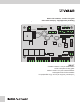 1
1
-
 2
2
-
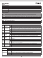 3
3
-
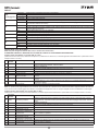 4
4
-
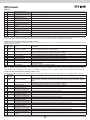 5
5
-
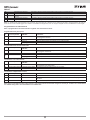 6
6
-
 7
7
-
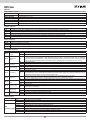 8
8
-
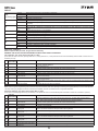 9
9
-
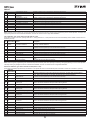 10
10
-
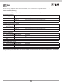 11
11
-
 12
12
-
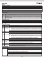 13
13
-
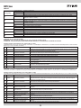 14
14
-
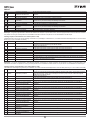 15
15
-
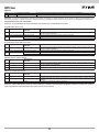 16
16
-
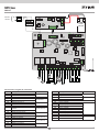 17
17
-
 18
18
-
 19
19
-
 20
20
-
 21
21
-
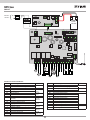 22
22
-
 23
23
-
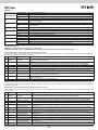 24
24
-
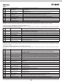 25
25
-
 26
26
-
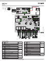 27
27
-
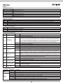 28
28
-
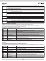 29
29
-
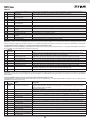 30
30
-
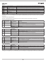 31
31
-
 32
32


Elvox Vimar SW12.T Instructions Sheet
- Tipo
- Instructions Sheet
- Questo manuale è adatto anche per
in altre lingue
- English: Elvox Vimar SW12.T
- français: Elvox Vimar SW12.T
- español: Elvox Vimar SW12.T
- Deutsch: Elvox Vimar SW12.T
Documenti correlati
Altri documenti
-
PRASTEL UNIK2ESK Manuale utente
-
Yamaha MRX-100 Manuale del proprietario
-
Genius JA592 Istruzioni per l'uso
-
-
-
-
-
Aprimatic ZT 71 Installation Instructions Manual
-
Key Gates RX2H Guida utente
-
SICK Sicherheits-Encoder Istruzioni per l'uso