Aprimatic ZT 71 Installation Instructions Manual
- Categoria
- Gate Opener
- Tipo
- Installation Instructions Manual
Questo manuale è adatto anche per

SISTEMA OLEODINAMICO
CANCELLI AD ANTA
BATTENTE CON
OPERATORE
OLEODINAMICO
INTRERRATO
Istruzioni per l'installazione
HYDRAULIC SYSTEM FOR
SWING-GATES WITH PUMP
UNIT AND UNDERGROUND
HYDRAULIC JACK
Installation instructions
SYSTEME
OLEODYNAMIQUE POUR
PORTAILS A VANTAIL
BATTANT AVEC
OPERATEUR
OLEODYNAMIQUE
ENTERRE
Instructions d’installation
ELEKTROHYDRAULISCHER
UNTERFLURDREHTORANTRIEB
Montageanleitung
SISTEMA OLEODINAMICO
PARA CANCELAS DE
PUERTA BATIENTE CON
OPERADOR
OLEODINAMICO
ENTERRADO
Instrucciones de instalación
Scopo del manuale
Questo manuale è stato redatto dal costruttore ed è parte integrante del prodotto.
Le informazioni in esso contenute sono direttte agli operatori esperti che eseguono l’ installazione e la manutenzione straordinaria.
Essi devono possedere competenze specifiche e particolari capacità per eseguire correttamente ed in sicurezza gli interventi di loro competenza. La costante osservanza
delle informazioni garantisce la sicurezza dell’uomo, l’economia di esercizio ed una piú lunga durata di funzionamento del prodotto. Al fine di evitare manovre errate con
il rischio di incidenti, è importante leggere attentamente questo manuale, rispettando scrupolosamente le informazioni fornite. Considerando che tale prodotto va installato
in abitazioni residenziali, l’operatore esperto, dopo aver effettuato l’intervento dovrá constatarne la corretta installazione ed il regolare funzionamento. Successivamente
dovrá istruire l’utente sull’uso corretto del prodotto rilasciando tutta la documentazione prevista dal costruttore.
L’indice descrittivo, posto all’inizio, consente facilmente la rintracciabilitá degli argomenti di interesse.
Purpose of the manual
This manual was drawn up by the manufacturer and is an integral part of the product.
The information it contains is addressed to expert operators that carry out the installation and maintenance operations.
They must have the specific qualifications and training to carry out this work correctly and under the maximum safety conditions.
Strict observance of the instructions contained in the manual will ensure safety, optimum operation and prolonged functioning of the product. To avoid incorrect
manoeuvres and therefore the risk of accidents, it is essential to read this manual with care and strictly follow all the instructions given. As this is a product to be installed
in residential buildings, the expert installer, after completing installation must verify that this has been performed correctly and that the product functions smoothly.
Subsequently, it is necessary to instruct the user on the correct use of the product providing all the documentation envisaged by the manufacturer.
The table of contents, at the beginning, makes it easy to find the topics of interest.
Objectif de la notice
Cette notice a été rédigée par le fabricant et fait partie intégrante du produit.
Les informations qui y sont contenues s’adressent aux opérateurs spécialisés qui effectuent les opérations d’installation et d’entretien extraordinaire.
Ceux-ci doivent posséder les compétences et les qualités requises pour effectuer de façon correcte et en toute sécurité les interventions dont ils sont chargés. La constante
observation de ces informations garantit la sécurité des personnes, une économie d’utilisation et une plus longue durée de vie du produit. Lire attentivement cette notice
et en respecter scrupuleusement les informations pour éviter toute fausse manoeuvre qui pourrait entraîner des accidents. Ce produit étant destiné aux habitations
résidentielles, après en avoir effectué la pose, l’opérateur devra en vérifier la bonne installation et le bon fonctionnement .
Il devra ensuite informer l’utilisateur de l’emploi correct du produit et lui remettre toute la documentation prévue par le fabricant.
Le sommaire détaillé, placé au début de la notice, permet de retrouver facilement les sujets à consulter.
Zweck der Montageanleitung
Das vorliegende Handbuch wurde vom Hersteller verfaßt und ist Bestandteil des Produkts.
Die darin enthaltenen Informationen richten sich an erfahrenes Personal, das sowohl die Installation als auch außerordentliche Wartungsarbeiten durchführt.
Dieses Personal muß über spezifische Fähigkeiten und Kompetenzen verfügen, um die Arbeit korrekt und unter sicheren Bedingungen durchführen zu können.
Die ständige Beachtung der Anweisungen gewährleistet Sicherheit, wirtchaftlichen Betrieb der Anlage und eine längere Lebensdauer des Produkts.
Zur Vermeidung von Fehlern, die zu Unfällen führen könnten, muß das vorliegende Handbuch aufmerksam durchgelesen und die darin enthaltenen Anweisungen genau
befolgt werden.
Da das Produkt im Privatwohnbereich installiert wird, muß das erfahrene Personal nach der Installation die korrekte Montage und den einwandfreien Betrieb überprüfen.
Anschließend muß es den Benutzer in den richtigen Gebrauch des Produkts einweisen und ihm die vom Hersteller vorgesehene Dokumentation aushändigen.
Das Inhaltsverzeichnis am Anfang des Handbuchs ermöglicht eine schnelle Ermittlung der jeweiligen Punkte.
Objetivo del manual
Este manual ha sido redactado por el constructor y forma parte integrante del producto. Las informaciones que contiene van dirigidas a los operadores especializados
encargados de las operaciones de instalación y mantenimiento extraordinario.
Dichos operadores deberán poseer la competencia especifica y las capacidades necesarias para llevar a efecto correctamente y en condiciones de seguridad las
operaciones de las que están encargados.
El cumplimiento constante de estas instrucciones garantiza seguridad del personal, economía de uso y un funcionamento más duradero del producto. A fin de evitar
maniobras incorrectas con el consiguiente riesgo de accidentes cabe leer con atención este manual y respetar escrupulosamente las instrucciones.
Puesto que el producto está destinado a la instalación en viviendas, el operador especializado, después de realizar la instalación, deberá comprobar la correcta ejecución
de la misma y el buen funciomento del producto.
También deberá enseñar al cliente cómo utilizar correctamente el producto, entregando toda la documentación facilitada por el constructor.
El índice descriptivo inicial permite encontrar con facilidad los temas que interesen.
PER UN CORRETTO MONTAGGIO LEGGERE ATTENTAMENTE LE ISTRUZIONI.
FOR A CORRECT ASSEMBLY, CAREFULLY READ THE FOLLOWING.
POUR UN ASSEMBLAGE CORRECT, LIRE ATTENTIVEMENT LES ISTRUCTIONS.
FÜR EINE KORREKTE INSTALLATION, DIESE ANLEITUNGEN SORGFÄLTING LESEN.
LEER ATENTAMENTE LAS INSTRUCCIONES PARA UN MONTAJE CORRECTO.
Cod.A1913000
ZT 71
ZT 72

GENERALITÁ /
GENERAL
/
GENERALITES /
ALLGEMEINES
/ GENERALIDAD
Dati tecnici
Technical data
Caractéristiques techniques
Technische Daten
Datos técnicos ....................................................................................................................................................................................................................... pag. 3
Caratteristiche generali
General features
Caracteristiques generales
Allgemeine merkmale
Caracteristicas generales .....................................................................................................................................................................................................
pag. 3
Dimensioni del complesso operatore oleodinamico interrato ZT 71 - ZT 72
Dimensions of the ZT 71 - ZT 72 underground hydraulic operator group
Dimensions du groupe actionneur hydraulique souterrain ZT 71 -ZT 72
Abmessungen des unterirdischen öldynamischen Antriebskomplexes ZT 71 – ZT 72
Dimensiones del grupo operador hidráulico enterrado ZT 71 - ZT 72 .............................................................................................................................
pag. 4
Specifica delle versioni dell’interrato ZT 71 - ZT 72
Specifications of the ZT 71 - ZT 72 underground versions
Spécifications des version du souterrain ZT 71 - ZT 72
Spezifikationen der Versionen des unterirdischen Komplexes ZT 71 – ZT 72
Especificaciones versiones enterrado ZT 71 -ZT 72 ..........................................................................................................................................................
pag. 5
CONTROLLI PRELIMINARI /
PRELIMINARY CHECKS / CONTROLES PREALABLES
VORKONTROLLEN / CONTROLES PREVIOS
Controlli preliminari
Preliminary checks
Contrôles préliminaires
Kontrollen vor der Montage
Controles previos ..................................................................................................................................................................................................................
pag. 6
Disposizione dei componenti (B2)
Arrangement of the components (B2)
Emplacement des elements constituant le systeme (B2)
Anordnung der bauteile (B2)
Distribucion de los componentes (B2) ................................................................................................................................................................................
pag. 7
Verifica componenti
Checking components
Verification generale
Nachprüfung der bestandteile
Verificacion componenetes ..................................................................................................................................................................................................
pag. 9
Elenco dei componenti operatore ZT 71 - ZT 72
Lst of the ZT 71 -ZT 72 operator components
Liste des cmposants de l’actionneur ZT 71 -ZT 72
Verzeichnis der Komponenten Trieb ZT 71 -ZT 72
Lista componentes operador ZT 71 -ZT 72..........................................................................................................................................................................
pag. 9
Preparazione al montaggio
Prepararion for installation
Preparation au montage
Vorbereitung zur montage
Preparacion a la instalacion .................................................................................................................................................................................................
pag. 11
ISTRUZIONI PER IL MONTAGGIO
/ INSTALLATION INSTRUCTIONS / NOTICES POUR LE MONTAGE
MONTAGESNLEITUNG / INSTRUCCIONES DE INSTALACCION
Cassetta di fondazione CIA 171
CIA 171 foundation box
Caisson de fondation CIA 171
Gründungskasten CIA 171
Cajón de fundación CIA 171 .................................................................................................................................................................................................
pag. 13
Installazione cassetta di fondazione CIA 171
Installation of the CIA 171 foundation box
Installation du caisson de fondation CIA 171
InstallationGründungskasten CIA 171
Instalación cajón de fundación CIA 171 ..............................................................................................................................................................................
pag. 14
Posizionamento della bussola
Positioning of the bush
Positionnement de la douille
Anbringung der Buchse
Colocación del casquillo .......................................................................................................................................................................................................
.pag. 15
1
INDICE
CONTENTS TABLE DES MATIERES INHALTSVERZEICHNIS INDICE
A
B
C

Installazione operatore ZT 71 (110°) ZT 72 (220°)
Installation of the ZT 71 (110°) ZT 72 (220°) operator
Installation de l’actionneur ZT 71 (110°) ZT 72 (220°)
Installation des Triebs ZT 71 (110°) ZT 72 (220°)
Instalacón del operador ZT 71 (110°) ZT 72 (220°) ..............................................................................................................................................................
pag. 16
Istruzioni per lo sfiato dell’apparecchiatura
Instructions to bleed the appliance
Instructions pour la purge du dispositif
Anleitung für die Entlüftung des Geräts
Instrucciones para la purga de aire del equipo ..................................................................................................................................................................
pag. 18
ATTIVAZIONE AUTOMAZIONE
/ ENABLING AUTOMATION / MISE EN SERVICE DE L’AUTOMATISATION
AKTIVIERUNG DES ANTRIEBS / ACTIVACION AUTOMATIZACION
Allacciamento elettrico
Electrical connections
Branchement electrique
Elektrischer anschluss
Conexion electrica .................................................................................................................................................................................................................
pag. 19
Regolazione delle pressioni e delle spinte
Adjustement of pressure and thrust
Reglage des pressions et des pousses
Einstellung von druck und schubkraft
Regulacion de las presiones y empoyes .............................................................................................................................................................................
pag. 21
Regolazione frenata in fase di apertura e chiusura
Adjustment of braking during opening and closing phases
Reglage du freinage lors de l’ouverture et de la frenature
Einstellung der abbremsung bei öffnungs-und schliessbewegung
Regulacion frenado en fase de apertura y cierre................................................................................................................................................................
pag. 22
Montaggio decentrato del martinetto
Off-center Jack fitting
Montage desaxe du verin
Versetzte drehzylindermontage
Instalacion de scentralizada del gato ..................................................................................................................................................................................
pag. 23
APPENDICE /
APPENDIX / NOTICE FINALES
ANLAGE / APENDICE
Guida ricerca guasti
Trouble -shooting
En cas de pannes
Fehlersuche
Guia de averias ......................................................................................................................................................................................................................
pag. 26
Istruzioni per l’utilizzatore
End user instruction
Instructions utilisateurs
Hinweise fur den benutzer
Instrucciones para el usuario ...............................................................................................................................................................................................
pag. 30
2
INDICE
CONTENTS TABLE DES MATIERES INHALTSVERZEICHNIS INDICE
D
E

- Il sistema, per l'azionamento di ogni singola anta, è composto da una centralina idraulica realizzata in differenti versioni di portata della pompa e da un
martinetto idraulico da incassare nel terreno in corrispondenza delle cerniere dell'anta del cancello.
- Il martinetto, prodotto in due versioni per l'apertura utile di 114° o 190°, dispone di un sistema regolabile per rallentare la velocità del cancello durante il suo
movimento nelle ultime fasi di apertura e di chiusura in modo da non fare sbattere il cancello sugli arresti; è costruito in struttura robusta da supportare ante
fino ad un peso di 800 Kg.
- La centralina idraulica è completa di valvole di regolazione della forza di apertura e chiusura così sensibili da garantire, una volta tarate in opera, la sicurezza
antischiacciamento; inoltre in tutte le versioni è prevista la valvola per lo sblocco di emergenza per il comando manuale del cancello.
- Le diverse versioni di blocco e portata pompa sono illustrate nella tabella dei dati tecnici.
- The system, for operating each single leaf, consists of an hydraulic pump unit produced with different pump capacity versions and an hydraulic jack to be buried
in the ground on which the gate hinges are aligned.
- The jack, produced in two versions for 114° or 190° opening, has an adjustable system to slow down the speed of the gate during the final opening and closing
stages of its movement to avoid banging the gate against its stops; it is built with a strong frame able to support leaves weighing up to a weight of 800 kg.
- The hydraulic pump unit is complete with opening and closing force adjustment valves that are calibrated in situ to guarantee the correct operation of the non-
crush safety device; furthermore all the versions have a built in emergency release valve for manual control of the gate.
CARATTERISTICHE GENERALI
ZT 71 ZT 72
temperatura di funzionamento
Working temperature
température de fonctionnement
Betriebstemperatur
temperatura de funcionamiento
peso con olio
Weight with oil (kg)
poids avec huile (Kg)
Gewicht mit Öl (Kg)
peso con aceite (kg)
olio tipo
Type of oil
type d’huile
Öltyp
tipo de aceite
45
-25° C / + 70° C
18
0,9 L
AprimOil HC13
DATI TECNICI
/ TECHNICAL DATA
DETAILS TECHNIQUES / TECHNISCHE DATEN
DATOS TECNICOS
pressione max. di esercizio (bar)
Max. working pressure (bar)
Pression maxi de service (bar)
Max. Betriebsdruck (bar)
presión máxima de ejercicio (bar)
tensione di alimentazione monofase
single-phase power supply
tension d’alimentation monophasée
Einphasige Betriebsspannung
tensión de alimentación monofásica
potenza assorbita (W)
Absorbed power (W)
puissance absorbée (W)
Aufnahmeleistung (W)
potencia absorbida (W)
3
A
DATI TECNICI TECHNICAL DATA CARACTERISTIQUES TECHNIQUES TECHISCHE DATEN DATOS TECNICOS
250
Quantità olio
Quantity of oil (l)
quantité d’huile (l)
Ölmenge (l)
cantidad aceite (l)
peso max. dell’anta da movimentare (Kg)
Max. weight of wing to be moved (kg)
poids max. du vantail à manoeuvrer (kg)
Max. Flügelgewicht (kg)
peso máx. de la puerta (kg)
velocità angolare con pompa da 0,75 lt./min.
Angular speed with 0.75 l/min pump
vitesse angulaire avec pompe de 0,75 l/min
Drehgeschwindigkeit mit Pumpe 0,75 l/min.
velocidad angular con bomba de 0,75 l/min.
velocità angolare con pompa da 0,6 lt./min.
Angular speed with 0.6 l/min pump
vitesse angulaire avec pompe de 0,6 l/min
Drehgeschwindigkeit mit Pumpe 0,6 l/min.
velocidad angular con bomba de 0,6 l/min.
max. angolo utile di lavoro
Max. working angle
angle utile de travail maximal
Max. Nutzöffnungswinkel
máx. ángulo útil de trabajo
angolo totale di rotazione
Total rotation angle
angle total de rotation
Gesamt-Öffnungswinkel
ángulo total de rotación
114°
190°
6°/sec
6°/sec
7°/sec
7°/sec
800
800
124°
200°
GENERAL FEATURES
250
230 V±10%50÷60 Hz 230 V±10%50÷60 Hz
45
-25° C / + 70° C
19,4
0,95 L
AprimOil HC13
portata pompa (lt./min.)
Pump capacity (l/min)
débit de pompe (l/min)
Pumpenfördermenge (l/min)
caudal bomba (L/min)
0,6 0,75 0,6 0,75
B4 B5 SF4 SF5
ZT 71 ZT 72

4
A
TIPOLOGIA DI BASCULANTI NON AUTOMATIZZABILI CON OPERATORE SERIE EM 51
- The different block and pump capacity versions are illustrated in the technical data table.
- Le système, pour l’entraînement de chaque vantail, se compose d’une centrale hydraulique réalisée en plusieurs versions selon le débit de pompe et d’un vérin
hydraulique à encastrer dans le sol à l'aplomb des gonds du vantail du portail.
- Le vérin, fabriqué en deux versions pour l’ouverture utile de 114° ou 190°, dispose d’un système réglable permettant de ralentir la vitesse du portail en fin
d’ouverture et de fermeture, l’empêchant ainsi de claquer sur les butées; la structure est en construction robuste pouvant supporter un vantail pesant jusqu’à
800 Kg.
- La centrale hydraulique est équipée de soupapes de réglage de la force d’ouverture et de fermeture d’une grande sensibilité assurant, une fois réglées lors
de la mise en oeuvre, la sécurité anti-écrasement; de plus, toutes les versions prévoient un bouton pour le déverrouillage d’urgence permettant la commande
manuelle du portail.
- Les différentes versions à blocage et de débit de pompe figurent au tableau des détails techniques.
- Das System zum Antrieb jedes einzelnen Flügels besteht aus einem Hydraulikaggregat, das in verschiedenen Ausführungen mit unterschiedlicher
Pumpenfördermenge angeboten wird, sowie aus einem Antriebszylinder, der in den Boden einzulassen ist, an dem die Scharniere der Torflügel angebracht
sind.
- Der Drehzylinder, hergestellt in zwei Versionen mit verschiedenen Nutz Öffnungswinkeln von 114° und 190°, verfügt über ein regulierbares System zur
Abbremsung der Geschwindigkeit im letzten Teil der Öffnungs- und Schließbewegung, so daß das Tor nicht heftig gegen die Anschläge stößt; er besteht aus
einer robusten Struktur, ist für ein Torflügelgewicht bis 800 kg.
- Das Hydraulikaggregat ist mit Ventilen zur Einstellung der Öffnungs- und Verschlußkraft versehen. Diese Ventile werden nach der Installation eingestellt und
garantieren für den Quetschschutz, außerdem ist in allen Ausführungen ein Ventil für die manuelle Not-Entriegelung des Tors vorgesehen.
- Die verschiedenen Ausführungen mit unterschiedlichen Blockierungen und Pumpenfördermengen werden in der Tabelle Technische Daten dargestellt.
- El sistema, para el accionamiento de cada puerta batiente, consta de una centralita hidráulica fabricada en diferentes versiones de caudal de bomba y de
un gato hidráulico a encajar en el suelo en correspondencia con las bisagras de la puerta.
- El gato, fabricado en dos versiones para una apertura útil de 114° o 190°, cuenta con un sistema regulable para disminuir la velocidad de la puerta durante
su movimiento en las últimas fases de apertura y cierre para que esta no golpee bruscamente en los topes. Su estructura es robusta y capaz de soportar puertas
hasta un peso de 800 kg.
- La centralita hidráulica se provista de válvulas de regulación de la fuerza de apertura y cierre tan sensibles que pueden garantizar, una vez calibradas en
obra, la seguridad anti-aplastamiento. Además, en todas las versiones se ha previsto la válvula para el desbloqueo de emergencia para mover manualmente
la puerta.
- Las diferentes versiones de bloqueo y caudal se ilustran en el cuadro de los datos técnicos.
CARACTERISTIQUES GENERALES
ALLGEMEINE MERKMALE
A1
CARACTERISTICAS GENERALES
DIMENSIONI DEL COMPLESSO OPERATORE OLEODINAMICO INTERRATO ZT 71 - ZT 72
DIMENSIONS OF THE ZT 71 - ZT 72 UNDERGROUND HYDRAULIC OPERATOR GROUP
DIMENSIONS DU GROUPE ACTIONNEUR HYDRAULIQUE SOUTERRAIN ZT 71 -ZT 72
ABMESSUNGEN DES UNTERIRDISCHEN ÖLDYNAMISCHEN ANTRIEBSKOMPLEXES ZT 71 – ZT 72
DIMENSIONES DEL GRUPO OPERADOR HIDRÁULICO ENTERRADO ZT 71 - ZT 72
B
A
CB
B
A
E
A
D
C
A (mm)
B (mm)
C (mm)
D (mm)
MODELLO ZT 71 ZT 72
290
151
140
45
355
151
140
45
E (mm)
20,5 45
A (mm)
B (mm)
270,5
380,5
CASSETTA CIA 171

SPECIFICA DELLE VERSIONI DELL’INTERRATO ZT 71 -ZT 72
5
A
B Modello con Doppio Blocco idraulico in apertura e chiusura. L'uso di questa versione è limitata sia dal peso dell'anta che dalla sua lunghezza. Viene prodotto in due versioni:
B4 .........velocità bassa.....................Peso max. anta 800 Kg. ...................................Lunghezza Max. anta 2,0 mt.
B5 .........velocità alta ........................Peso max. anta 400 Kg. ................................... Lunghezza Max. anta 1,7 mt.
SF Senza Blocco Idraulico-Frenato; con questo modello l'anta è movimentabile a mano con una leggera resistenza al moto.
Il modello S necessita di ELETTROSERRATURA ed
è prodotto in due versioni a seconda del peso e della lunghezza dell'anta:
SF4 ...... velocità bassa .....................Peso max. anta 800 Kg. ...................................Lunghezza Max. anta 4,0 mt.
C Blocco idraulico solo in chiusura (fornibile solo a richiesta). L'utilizzo di questo modello è limitato dal peso e dalla lunghezza dell'anta come per il modello B.
ATTENZIONE
La scelta del modello da utilizzare dipende non solo dal peso e dalla lunghezza dell'anta, ma anche dalle caratteristiche applicative dell'automazione e dallo stato dell'anta
da muovere (vedi paragrafo CONTROLLI PRELIMINARI e VERIFICA SCELTA AUTOMAZIONE).
B Model with double hydraulic lock on opening and closing. The use of this version depends on the weight of the gate and its length. It is produced in two versions:
B4 ......... low speed ..........................Max. leaf weight 800 kg................................................ Max leaf length 2.0 m
B5 ......... high speed .........................Max. leaf weight 400 kg................................................Max leaf length 1.7 m
SF Without Hydraulic Lock; with this model the gate can be moved by hand with a slight pressure.
The S model requires an ELECTRIC LOCK and is produced in two versions for
different gate weights and lengths:
SF4 ...... low speed ...........................Max. leaf weight 800 kg................................................ Max leaf length 4.0 m
C Hydraulic lock only on closing (supplied only on request). The use of this model depends on the weight and length of the gate as for model B.
ATTENTION
The choice of model to be used does not just depend of the weight and length of the gate, but also on the working features of the automatic device and the condition of
the gate to be moved (see paragraph on PRELIMINARY CONTROLS and CORRECT AUTOMATION SELECTION)
B Modèle avec double verrouillage hydraulique en ouverture et fermeture. L’emploi de cette version est limitée aussi bien par le poids du vantail que par sa largeur. Il est fabriqué
en deux versions:
B4 .........petite vitesse .............. Poids maxi du vantail 800 Kg ................... largeur maxi du vantail 2,0 m
B5 .........vitesse élevée............. Poids maxi du vantail 400 Kg ................... largeur maxi du vantail 1,7 m
SF Sans Verrouillage Hydraulique-Freiné; avec ce modèle le vantail peut être manoeuvré à la main avec une légère résistance au mouvement.
Le modèle S exige une
ELECTROSERRURE et est fabriqué en deux versions selon le poids et la largeur du vantail:
SF4 ...... petite vitesse .............. Poids maxi du vantail 800 Kg ................... largeur maxi du vantail 4,0 m
C Verrouillage hydraulique en fermeture seulement (ne peut être fourni que sur demande). L’emploi de ce modèle est limité par le poids et par la largeur du vantail, comme pour le
modèle B.
ATTENTION
Le choix du modèle à utiliser dépend non seulement du poids et de la largeur du vantail, mais aussi des caractéristiques d’application de l’automatisation et de l’état du
vantail à manoeuvrer (voir paragraphe des CONTRÔLES PRÉLIMINAIRES et VÉRIFICATION DU CHOIX DE L’AUTOMATISATION).
B Modell mit doppelter Hydraulikblockierung beim Öffnen und Schliessen. Die Einsatzmöglichkeiten dieser Ausführung werden sowohl vom Gewicht des Torflügels als auch von
dessen Länge begrenzt. Hergestellt werden zwei Ausführungen:
B4 ......geringe Geschwindigkeit ........... max. Torflügel-Gewicht 800 kg ...................... max. Torflügel-Länge 2,0 m
B5 ......hohe Geschwindigkeit ............... max. Torflügel-Gewicht 400 kg ...................... max. Torflügel-Länge 1,7 m
SF Ohne hydraulische Blockierung/Bremse: bei diesem Modell kann der Torflügel mit geringfügigem Widerstand von Hand bewegt werden.
Das Modell S erfordert den Einbau von
einem ELEKTROSCHLOSS und wird je nach Gewicht und Länge des Torflügels in 2 Ausführungen angeboten:
SF4 ....geringe Geschwindigkeit ........... max. Torflügel-Gewicht 800 kg ...................... max. Torflügel-Länge 4,0 m
C Hydraulikblockierung nur bei geschlossenem Tor (nur auf Anfrage lieferbar). Die Einsatzmöglichkeiten dieser Ausführung werden wie bei Modell B vom Gewicht und der Länge
des Torflügels begrenzt.
ACHTUNG
Die Wahl des richtigen Modells hängt nicht nur vom Gewicht und von der Länge des Torflügels ab, sondern auch von der vorgesehenen Einbauart des Antriebs und vom
Zustand des Torflügels ab (siehe Paragraph “Vorkontrolle und Nachprüfung der Antriebswahl”)
B Modelo con Doble Bloqueo Hidráulico en apertura y cierre. El uso de esta versión está limitado por el peso de la puerta y su largo. Se fabrica en dos versiones :
B4 .........velocidad baja ....................Peso máx. puerta 800 Kg........................................ Largo máx. puerta 2.0 m
B5 .........velocidad alta .....................Peso máx. puerta 400 Kg........................................ Largo máx. puerta 1,7 m
SF Sin Bloqueo hidráulico frenado; con este modelo se hace el movimiento manual de la puerta superando una ligera resistencia al movimiento.
El modelo S precisa de la
electrocerradura y se fabrica en dos versiones de acuerdo con el peso y el largo de la puerta :
SF4 ...... velocidad baja ....................Peso máx. puerta 800 Kg........................................ Largo máx. puerta 4,0 m
C Bloqueo hidráulico sólo durante el cierre ( sólo bajo pedido). El uso de este modelo está limitado por el peso y el largo de la puerta como en el caso del modelo B.
ATENCION
La elección del modelo depende no sólo del peso y del largo de la puerta, sino también de las características de aplicación de la automatización y de la situación de la
puerta a mover ( véase párrafo controles previos y verificación opciones de automatización)
SPECIFICATIONS OF THE ZT 71 - ZT 72 UNDERGROUND VERSIONS
SPÉCIFICATIONS DES VERSION DU SOUTERRAIN ZT 71 - ZT 72
SPEZIFIKATIONEN DER VERSIONEN DES UNTERIRDISCHEN KOMPLEXES ZT 71 –ZT 72
ESPECIFICACIONES VERSIONES ENTERRADO ZT 71 - ZT 72

6
B
CONTROLLI PRELIMINARI
Prima di eseguire il lavoro di installazione occorre verificare le condizioni del cancello da automatizzare:
- La costruzione meccanica deve essere robusta e rigida.
- Le cerniere non devono avere giochi o forti attriti e devono essere adeguate al peso dell'anta.
- Verificare che l'anta sia perfettamente a piombo.
- Verificare che non vi siano cedimenti del pilastro o delle cerniere fissate allo stesso.
ATTENZIONE
• Nel caso si rilevino anomalie occorre procedere al ripristino delle buone condizioni di funzionamento dell'anta prima di procedere all'installazione; è bene tenere
presente che ogni anomalia geometrica o strutturale del cancello potrebbe causare, nel tempo, pericolosi sovraccarichi sul martinetto.
• Se non sono presenti, è obbligatorio prevedere gli arresti a terra (B1 ➀) delle ante, sia in apertura che in chiusura, in modo da non superare mai l'angolo utile di lavoro
del martinetto indicato in figura B1. È consigliabile posizionare gli arresti a terra prima di effettuare l'installazione.
Before going ahead with installation first check the condition of the gate to be automated:
- The mechanical construction must be strong and stiff
- The hinges must not have any play or strong friction and must be adequate for the weight of the gate.
- Check that the gate hinges are perfectly perpendicular (at plumb).
- Check that the gate-post and the hinges fixed to it are secure.
ATTENTION
• If any faults are detected, the gate must be restored to good working order before installing the automatic device; it should be remembered that any geometric or
structural fault on the gate can, in time, cause dangerous overloading of the jack.
• Where they are not already present it is essential to fit ground stops (B1
➀
) for the open and the closed leaf so that it never goes beyond the working angle of the jack,
indicated in figure B1. It is advisable to position the ground stops before installation.
Avant d’effectuer le travail d’installation, vérifier l’état du portail à automatiser:
- La construction mécanique doit être robuste et rigide.
- Les charnières doivent être sans jeu ni frottement et doivent être appropriées au poids du vantail.
- Vérifier que le vantail
soit parfaitement d’aplomb.
- Vérifier que le pilier ou les gonds qui y sont fixés ne cèdent pas.
ATTENTION
• Si vous remarquez des anomalies, il faut rétablir les bonnes conditions de fonctionnement du vantail avant d’effectuer l’installation; il convient de se rappeler que toute
anomalie géométrique ou structurale du portail pourrait causer, dans le temps, de dangereuses surcharges sur le vérin.
• Si cela n’a pas encore été fait, il est impératif de prévoir des butées (B1
➀
) du vantail au sol aussi bien en ouverture qu’en fermeture afin de ne jamais dépasser l’angle
utile de travail du vérin indiqué à la figure B1. Nous conseillons de placer les butées au sol avant d’effectuer l’installation.
Vor Installation sollte der Zustand des zu automatisierenden Tors geprüft werden:
- Die Torkonstruktion sollte robust und starr sein.
- Die Scharniere dürfen kein Spiel oder starke Reibung aufweisen und müssen das Torflügelgewicht problemlos tragen.
- Kontrollieren, ob der Torflügel
perfekt im Lot ist.
- Sicherstellen, daß der Pfosten oder die daran befestigten Scharniere nicht verbogen oder verformt sind.
ACHTUNG
• Sollten Mängel am Tor festgestellt werden, dann sind diese vor Installation des Antriebs zu beseitigen. Jeder geometrische oder strukturelle Mangel des Tor kann im
Laufe der Zeit zu gefährlicher Überlastung des Drehzylinders führen.
• Falls nicht vorhanden, müssen am Boden Endanschläge angebracht werden (B1
➀
) sowohl für die völlige Öffnung als auch das Schliessen des Tors, so daß der in
Abbildung B1 angegebene Nutzarbeitswinkel des Drehzylinders nie überschritten wird. Es empfiehlt sich, die Bodenanschläge vor der Installation anzubringen.
Antes de realizar el trabajo de instalación hace falta verificar las condiciones de la cancela por automatizar :
- La construcción mecánica debe ser robusta y rígida
- Las bisagras no deben tener juegos o fuertes roces y deben adaptarse al peso de la puerta.
- Asegurarse que la puerta
esté a plomo.
- Comprobar que no haya hundimiento del pilar o de las bisagras sujetadas al mismo
ATENCION
• Si se detectan anomalías hace falta restablecer las buenas condiciones de funcionamiento de la puerta antes de realizar la instalación. Es importante considerar que
cualquier anomalía geométrica y de estructura de la cancela podría ocasionar, con el tiempo, sobrecargas en el gato.
• Si no están, es obligatorio prever los topes de parada al suelo (B1
➀
) de las puertas tanto en apertura como en cierre para no rebasar nunca el ángulo de trabajo del
gato (cf figura B1). Les aconsejamos que posicionen los topes al suelo antes de realizar la instalación.
PRELIMINARY CHECKS
CONTROLES PREALABLES
VORKONTROLLEN
CONTROLES PREVIOS
B 1

DISPOSIZIONE DEI COMPONENTI (B2)
A- Lampeggiatore Aprimatic (posizionare in un punto ben visibile da entrambi i lati del transito)
B- Fotocellula di sicurezza Aprimatic
C- Dispositivo di comando manuale a chiave (magnetica, digitale, combinatore a tastiera, meccanica, ecc.)
D- Apparecchiatura di comando Aprimatic a microprocessore in contenitore stagno (posizionare, possibilmente, al riparo da agenti atmosferici) (vedere listino)
E- Radio ricevente telecomando Aprimatic (possibilità di inserimento all'interno del lampeggiatore) (modello RG/RR - vedere listino)
F- Condotta per cavo di alimentazione della centralina idraulica proveniente dalla apparecchiatura elettrica
G- Antenna (optional)
H- ZT 71 - ZT 72 incassati ai piedi dei pilastri
I-Arresto meccanico in apertura e chiusura
L- Messa a terra delle strutture metalliche
M- Scatola di derivazione per impianto elettrico.
N.B.: Per ulteriori dispositivi di sicurezza (optional) consultare il listino prezzi.
ARRANGEMENT OF THE COMPONENTS (B2)
EMPLACEMENT DES ELEMENTS CONSTITUANT LE SYSTEME (B2)
A- Aprimatic flashing light (place in a point clearly visible when approaching the gate on either side)
B- Aprimatic safety photocell
C- Manual key control (magnetic, digital, key-pad, mechanical, etc.)
D- Aprimatic microprocessor control unit in sealed box (position, were possible, so that it is protected against the atmospheric agents) ( see price list)
E- Aprimatic remote control receiver (can be fitted inside the flashing lamp) (model RG/RR)
F- Tube for hydraulic control unit power supply cable coming from the control unit.
G- Antenna (optional)
H- ZT 71 - ZT 72 embedded in the pillar feet
I-Mechanical stop for opening and closing
L -Earth for the metal structures
M -Branch box for electrical system
N.B. For other safety devices (optional) please refer to the catalogue or price list.
A- Lampe clignotante Aprimatic (placer à un endroit bien visible des deux côtés du passage)
B- Photocellule de sécurité Aprimatic
C- Dispositif de commande manuelle à clé (magnétique, digitale, clavier à combinaison, mécanique, etc.)
D- Armoire de commande Aprimatic à microprocesseur en boîtier étanche (l’installer, si possible, à l’abri des agents atmosphériques) ( voir tarif)
E- Radio récepteur avec télécommande Aprimatic (pouvant être installé à l’intérieur de la lampe clignotante) (model RG/RR - voiv tarit)
F- Conduite pour le câble d’alimentation de la centrale hydraulique provenant de l’armoire électrique
G- Antenne (en option)
H
-
ZT 71 - ZT 72 encaissés aux pieds des piliers
I- Butée mécanique en ouverture et fermeture
L- Mise à la terre des structures métalliques
M - Boîtier de dérivation pour installation électrique
N.B. Si vous désirez des dispositifs de sécurité supplémentaires (en option), consulter le tarif.
7
B

A- Blinkmelder Aprimatic (an von beiden Torseiten aus gut sichtbarer Stelle anbringen)
B- Sicherheitslichtschranke Aprimatic
C- Vorrichtung zur manuellen Bedienung mit Schlüssel (Magnetkarte, Digitaleinrichtung, Tastatur, Mechanischer Schlüssel, usw.)
D- Mikroprozessor-Steuerung Aprimatic in wasserdichtem Gehäuse (möglichst an witterungsgeschützter Stelle installieren) (siehe Preisliste)
E- Funkempfänger mit Fernbedienung Aprimatic (mögliche Installation im Blinkmelder) (Modell RG/RR - siehe Preisliste)
F- Leitung für Versorgungskabel von der elektrischen Anlage an das Hydraulikaggregat
G- Antenne (Sonderzubehör)
H
-
ZT 71 – ZT 72 in die Pfeilerfüße eingelassen
I-Mechanischer Anschlag bei Öffnung und Schließvorgang
L- Erdung der Metallkonstruktionen
M-
Abzweigdose für Elektroanlage
Wichtig: Für weitere Sicherheitseinrichtungen (Sonderzubehör) siehe Preisliste.
A- Destellador Aprimatic (posicionar en un punto perfectamente visible de ambos lados del tránsito)
B- Célula fotoeléctrica de seguridad Aprimatic
C- Dispositivo de mando manual a llave ( magnética, digital, combinador de teclado, mecánica, etc.)
D- Cuadro de maniobras Aprimatic con microprocesador en caja estanca (colocar, si es posible el cuadro fuera del alcance de los agentes externos) (véaselista)
E- Radio receptor mando a distancia Aprimatic (posibilidad de inserción en el destellador) (modelo RG/RR - véase lista)
F- Canalizacion para cable de alimentación de la centralita hidráulica procedente del equipo eléctrico
G- Antena ( opcional)
H-
ZT 71 - ZT 72 enterrados a los pies de los pilotes
I-Tope mecánico en apertura y cierre
L- Puesta a la tierra de las estructuras metálicas
M-
Caja de derivación para instalación eléctrica
N.B. : Para otros dispositivos de seguridad (opcionales) consultar la lista de precios.
ANORDNUNG DER BAUTEILE (B2)
DISTRIBUCION DE LOS COMPONENTES (B2)
B 2
8
B

9
Prima di effettuare il montaggio è necessario verificare la scelta dell’automazione in funzione delle
caratteristiche e delle dimensioni dell’elemento da movimentare, dal modo di utilizzo dell’automazione e
dalle caratteristiche ambientali. L’esperienza è il migliore aiuto in questi casi, tuttavia consigliamo di seguire
alcuni criteri (B3).
Before beginning assembly, check that the packaging contains all the components listed below and that
these are not damaged. Check also that the model serial number on the packing case corresponds to the
one on the plaque (B3).
Avant de commencer le montage, contrôler que l’emballage contienne toutes les pièces énumérées ci-
après et qu’elles ne soient pas endommagées. Vérifier également que la référence du modèle indiqué sur
la boîte d’emballage correspond à celle figurant sur la plaquette de l’article (B3).
Vor Beginn mit der Montage sollte kontrolliert werden, ob in der Verpackung alle Bestandteile enthalten sind, die
nachfolgend aufgelistet werden. Die Teile dürfen nicht beschädigt sein. Außerdem kontrollieren, ob die Modell-
Kennummer auf der Verpackung mit der Kennummer auf dem Schild des Antriebs übereinstimmt (B3).
Antes de empezar el montaje controlar que el embalaje contenga todos los componentes listados a
continuación y que los mismos no estén estropeados. Asegurarse asimismo que la sigla del modelo
indicado en la caja del embalaje corresponda a la indicada en la plaquita del producto (B3).
B
VERIFICA COMPONENTI
CHECKING COMPONENTS
VERIFICATION GENERALE
NACHPRÜFUNG DER BESTANDTEILE
VERIFICACION COMPONENTES
B 3
CENTRALINA-MARTINETTO
CONTROL UNIT-CYLINDER
CENTRALE-VÉRIN
STEUEREINHEIT-ZYLINDER
CENTRALITA-CILINDRO
ELENCO DEI COMPONENTI OPERATORE ZT 71 - ZT 72
* CASSETTA CIA 171 (B5)
Pos. Descrizione
1 Coperchio cassetta Qt.1
2 Tappi plstica nera Qt.2
3 Viti TE 6x14 + rosette Qt.2
4 Attacco scanalato Qt.1
5 Boccola sinterizzata Qt.1
6 Viti TE 10x25 + dadi ES.M10 Qt.2
7 Dima per messa in fase martinetto Qt.1
* Venduta separatamente - Vedere listino
CENTRALINA-MARTINETTO (B4)
Pos. Descrizione
1 Centralina ZT 70 Qt.1
2 Marinetto ZT 71 o ZT 72 Qt.1
3 Valvola di sfiato Qt.1
4 Chiave triangolare Qt.1
5 Viti sollevamento martinetto TCCE 12x40 Qt.4
6 Condendatore 8 microF 400V 15 cm Qt.1
CONTROL UNIT - CYLINDER (B4)
Pos. Description
1 ZT 70 control unit 1 pc.
2 ZT 71 - ZT 72 cylinder 1 pc.
3 Air vent 1 pc.
4 Triangular key 1 pc.
5 Cylinder lifting Allen screws 12x40 4 pcs.
6 8 microF 400V 15 cm. capacitor 1 pc.
* CIA 171 BOX (B5)
Pos. Description
1 Box cover 1 pc.
2 Black plastic plugs 2 pcs.
3 Hexagon head cap screws 6x14 + washers 2 pcs.
4 Grooved attachment 1 pc.
5 Sintered bush 1 pc.
6 Hexagon head cap screws 10x25 +
+ hexagon nuts M10 2 pcs.
7 Template for cylinder phase adjustment 1 pc.
* Sold separately - See price-list
CENTRALE - VÉRIN (B4)
Pos. Désignation
1 Centrale ZT 70 Q.té 1
2 Vérin ZT 71- ZT 72 Q.té 1
3 Soupape de purge Q.té 1
4 Clé triangulaire Q.té 1
5 Vis de levage vérin à six pans creux 12x40 Q.té 4
6 Condensaateur 8 microF 400V 15 cm. Q.té 1
* BOÎTIER CIA 171 (B5)
Pos. Désignation
1
Couvercle boîtier
Q.té 1
2 Bouchons en plastique noire Q.té 2
3 Vis à tête hexagonale 6x14 + rondelles Q.té 2
4 Connexion rainée Q.té 1
5 Douille frittée Q.té 1
6 Vis à tête hexagonale 10x25 +
+ écrous hexagonaux Q.té 2
7 Gabarit pour mise en phase vérin Q.té 1
* Vendue separement - Voir tarif
F
ON
LiST OF THE ZT 71 - ZT 72 OPERATOR COMPONENTS
LISTE DES COMPOSANTS DE L’ACTIONNEUR ZT 71 - ZT 72

10
B
STEUEREINHEIT - ZYLINDER (B4)
Pos. Bezeichnung
1 Steuereinheit ZT 70 1.St
2 Zylinder ZT 71 - ZT 72 1.St
3 Entlüftungsventil 1.St
4 Dreiecksschlüssel 1.St
5 Hubschrauben Zylinder Innensechskant 12x40 4.St
6 Kondensator 8 microF 400V 15cm. 1.St
* KASTEN CIA 171 (B5)
Pos. Bezeichnung
1 Kastendeckel 1.St
2 Plastikvershlüssel 2.St
3 Sechskantschrauben 6x14 + Scheiben 2.St
4 Nutanschluss 1.St
5 Gesinterte Buchse 1.St
6 Sechskantschrauben 10x25 +
+ Sechskantmuttern 2.St
7 Schablone für Phaseneinstellung Zylinder 1.St
* Einzeln verkauft - Siehe Preisliste
CENTRALITA - CILINDRO (B4)
Pos. Descripción
1 Centralita ZT 70 Cdad.1
2 Cilindro ZT 71 - ZT 72 Cdad.1
3 Válvula de purga de aire Cdad.1
4 Llave triangular Cdad.1
5 Tornillos de cabeza cilíndrica con hexágono
interior para levantamiento cilindro 12x40 Cdad.4
6 Condensador 8 microF 400V 15cm. Cdad.1
* CAJA CIA 171 (B5)
Pos. Descripción
1 Tapadera caja Cdad.1
2 Tapones de plástico negro Cdad.2
3 Tornillos de cabeza hexagonal 6x14 +
+ tuercas hexagonales M10 Cdad.2
4 Empalme ranurado Cdad.1
5 Casquillo sinterizado Cdad.1
6 Tornillos de cabeza hexagonal 10x25 +
+ tuercas hexagonales M10 Cdad.2
7 Plantilla para regulación cilindro Cdad.1
B 4
B 5
1
2
7
4
5
2
1
3
3
1
2
7
6
5
VERZEICHNIS DER KOMPONENTEN TRIEB ZT 71 - ZT 72
LISTA COMPONENTES OPERADOR ZT 71 - ZT 72
* Vendida separadamente - Ver lista de precios
5
3
6
4

11
B
Il montaggio dell’operatore richiede una serie di lavori di preparazione del cancello da movimentare da eseguirsi, se il cancello è già installato, direttamente sul
luogo dell'installazione; è quindi necessario premunirsi dell'attrezzatura adatta che consenta all'installatore la massima autonomia durante il lavoro.
AVVERTENZA
L'elenco dell'utensileria necessaria, è riportato nella figura, comprensiva di tabella, (B 6).
PREPARAZIONE AL MONTAGGIO
l Livella a bolla (tridimensionale)
l Grasso tipo grafitato.
l Olio tipo AprimOil HC 13 (olio espressamente formulato per Aprimatic)
l Bomboletta Zincospray
l Vernice antiruggine
l Pennelli per verniciatura
l Diluente per pulizia pennelli
l Spazzola metallica
l Lime varie
l Punte da tracciatura
l Martello
l Scalpello per acciaio e per muratura
l Salviette detergenti
l Carta per asciugatura mani
l Cassetta "Pronto soccorso"
ATTREZZATURA BASE E MATERIALE DI CONSUMO OCCORRENTE
l Occhiali di protezione
l Maschera di protezione
l Saldatore da stagno
l Trapano elettrico di potenza adeguata alimentazione 220 V.
l Punte da trapano
l Fresa a tazza ø 67 per fori alloggiamento fotocellule e pulsantiere
l Cavo di prolunga per attrezzatura elettrica
l Cavo elettrico sez. 1,5 mm
2
vari colori + capicorda vario tipo
l Forbici da elettricista
l Pinze per capicorda
l Tester
l Calibro ventesimale
l Metro
l Goniometro
l Dinamometro
The installation of the pump unit requires a series of preparatory operations on the gate to be automated, if the gate is already installed, at the installation site;
it is therefore necessary to prepare the equipment that will give the installer maximum autonomy.
WARNING
The list of tools necessary is given in the figure, including the table, (B 6)
PREPARARION FOR INSTALLATION
l
Dynamometer
l
Plumb line
l
Spirit level (three-dimensional)
l
Graphite type grease
l
AprimOil HC 13 type oil (oil specially formulated for Aprimatic)
l
Zincospray canister
l
Rust inhibitor paint
l
Pain brushes
l
Metal brush
l
Various files
l
Iron saws
l
Marking bits
l
Hammer
l
Metal and masonry chisels
l
Wipe clean tissues
l
Paper towels
l
First Aid box
BASIC EQUIPMENT AND DISPOSABLE MATERIAL REQUIRED
l
Protective goggles
l
Protective mask
l
Soft soldering iron
l
Electric drill: 220V
l
Drill bits
l
Cup milling cutter dia. 67 for photocell and push-button sheet-panel
housings
l
Extension cable for electrical equipment
l
Electric cable 1.5 mm
2
in various colours + various types of cable terminals
l
Electrician’s scissors
l
Cable terminal grippers
l
Tester
l
Calliper in twentieths
l
Measuring stick
PREPARATION AU MONTAGE
Le montage de l’opérateur exige une série de travaux pour préparer le portail à manoeuvrer qui doivent être effectués, si le portail est déjà installé, directement
sur le lieu d’installation.; il est donc nécessaire de prévoir l’équipement adéquat qui donnera le maximum d’autonomie à l’installateur effectuant le travail.
AVERTISSEMENT
La liste de l’outillage nécessaire est indiquée sur la figure avec tableau (B 6).
EQUIPEMENT DE BASE ET MATÉRIEL DE CONSOMMATION NÉCESSAIRE
l
Lunettes de protection
l
Masque de protection
l
Fer à souder pour étain
l
Perceuse électrique avec puissance adéquate alimentation: 220V
l
Forets de perceuse
l
Fraise ø 67 pour trous de logement des photocellules et boutons-poussoirs
l
Câble de rallonge pour équipement électrique
l
Câble électrique sec. 1,5 mm
2
plusieurs couleurs + cosses de différents
types
l
Ciseaux d’électricien
l
Pinces à cosses
l
Testeur
l
Pied à coulisse vingtésimal
l
Mètre
l
Rapporteur
l
Fil à plomb
l
Niveau à bulle (tridimensionnel)
l
Graisse du type graphitée
l
Huile type AprimOil HC 13
(huile formulée expressément pour Aprimatic)
l
Zinc spray
l
Peinture anti-rouille
l
Pinceaux pour peindre
l
Diluant pour nettoyer les pinceaux
l
Brosse métallique
l
Assortiment de limes
l
Pointes de traçage
l
Marteau
l
Ciseau pour acier et maçonnerie
l
Serviettes détergentes
l
Papier essuie-mains
l
Boîte de secours

12
B
VORBEREITUNG ZUR MONTAGE
Zur Montage des Antriebs sind eine Reihe vorbereitender Maßnahmen am Tor erforderlich. Bei schon installiertem Tor erfolgen diese Eingriffe direkt am
Installationsort. Man sollte daher die erforderliche Ausrüstung vorbereiten, damit der Installateur die Arbeit ohne Unterbrechung und eigenständig vornehmen kann.
HINWEIS
Die Liste des erforderlichen Werkzeugs befindet sich auf der Abbildung mit der Tabelle (B6).
l
Dynamometer
l
Lotblei
l
Wasserwaage (dreidimensional)
l
Graphitiertes Schmierfett
l
Öl Typ AprimOil HC 13
(speziell für Aprimatic entwickeltes Öl)
l
Sprayflasche “Zincospray”
l
Rostschutzlack
l
Pinsel
l
Lösungsmittel zur Pinselreinigung
l
Metallbürste
l
Verschiedene Feilen
l
Anreissnadel
l
Hammer
l
Stahl- und Steinmeissel
l
Reinigungsservietten
l
Saugpapier
l
Erste Hilfe-Kasten
ERFORDERLICHE GRUNDAUSRÜSTUNG UND VERBRAUCHSMATERIAL
l
Schutzbrille
l
Schutzmaske
l
Lötkolben
l
Elektrische Bohrmaschine mit angemessener Leistung, Versorgung:
220 V
l
Bohrer
l
Topffräser Ø 67 für Aufnahmebohrungen Lichtschranken und Bedientafeln
l
Verlängerungskabel für elektrische Ausrüstung
l
Elektrokabel Schnitt 1,5 mm
2
verschiedenfarbig + verschiedene
Kabelschuhe
l
Elektrikerschere
l
Zangen für Kabelschuhe
l
Tester
l
l Lehre
l
Messband
PREPARACION A LA INSTALACION
La instalación del operador requiere una serie de trabajos de preparación de la cancela los cuales deberan llevarse a cabo si la cancela ya está instalada,
directamente en el lugar de obra. Es necesario por lo tanto equiparse con el utillaje adecuado para permitir al instalador la máxima autonomía durante el trabajo.
ADVERTENCIA
La lista del utillaje necesario se indica en la figura que incluye la tabla (B 6).
UTILLAJE BÁSICO Y MATERIAL DE CONSUMO NECESARIO
l
Gafas de protección
l
Máscara de protección
l
Soldador para estaño
l
Taladro eléctrico de potencia adecuada alimentación 220 V
l
Brocas para taladro
l
Fresa hueca Ø 67 para agujeros de alojamiento células fotoeléctricas y
tablero de pulsadores
l
Cable de prolongación para equipo eléctrico
l
Cable eléctrico sección 1,5 mm
2
diferentes colores + terminales varios tipos
l
Tijeras para electricista
l
Pinzas para terminales
l
Tester
l
Calibre vigesimal
l
Metro
l
Dinamómetro
l
Plomada
l
Nivel de burbuja (tridimensional)
l
Grasa tipo grafitada
l
Aceite de tipo AprimOil HC 13 (aceite especialmente formulado para
Aprimatic)
l
Zincospray
l
Barniz antioxidante
l
Pinceles para pintura
l
Diluyente para limpieza pinceles
l
Cepillo metálico
l
Limas diversas
l
Punzones para trazar
l
Martillo
l
Cincel para acero y mampostería
l
Servilletas detergentes
l
Papel para secarse las manos
l
Botiquín de urgencia
B 6
Chiave combinata 19
Combination wrench 19
Clé mixte 19
Kombischlüssel 19
LLave combinada 19 ........................
USAG 285/19
1
POS. .........................................................UTENSILE
POS. ................................................................ TOOL
POS. ............................................................... OUTIL
POS. ..................................................... WERKZEUG
POS. ................................................ HERRAMIENTA
5
CENTRALINA /
CONTROL UNIT/CENTRALE
STEUEREINHEIT
/
CENTRALITA
MARTINETTO /
CYLINDER / V
É
RIN
ZYLINDER
/ CILINDRO
OFF
ON
1
5
2
1
2
4
3
Chiave combinata 14
Combination wrench 14
Clé mixte 14
Kombischlüssel 14
LLave combinada 14 ........................
USAG 285/14
Chiave combinata 8
Combination wrench 8
Clé mixte 8
Kombischlüssel 8
LLave combinada 8 ...........................
USAG 285/8
Chiave a brugola maschio 6
Allen key 6
Clé mâle six pans 6
Imbussteckschlüssel 6
LLave allen macho 6........................
USAG 280T/6
Cacciavite
Screwdriver
Tournevis
Schraubendreher
Destornillador ..............................
USAG 326/5x150
2
3
4

CASSETTA DI FONDAZIONE CIA 171
C 1
C 2
Le casse di fondazione permettono di predisporre il cancello ad una successiva installazione
dell’operatore oleodinamico ZT71 - ZT72. Le modalità di posizionamento della cassetta sono le
seguenti:
- Controllare che tra l’asse di rotazione dell’anta ed il pilastro (o muro di sostegno) vi siano almeno
60 mm (C 1).
- Eseguire uno scavo, alla base del pilastro di supporto del cancello, dimensionato come indicato in C1
e C2 avendo cura che la base dello scavo stesso sia il più possibile in squadro (90°) rispetto al pilastro
del cancello.
AVVERTENZA
Prevedere in una zona dello scavo il drenaggio dell’acqua interrando, alla base dello scavo,
una quantità di ghiaia (C2(1)) corrispondente ad un secchio pieno oppure prevedendo un
condotto di scario.
The foundation box is designed to house ZT71 and ZT72 hydraulic gate operators to install the box
proceed as follows:
- Cheek that there is a space of at least 60 mm (C1) between the gate hinge pin and the gate post
(or supporting wall).
- Make a hole in the ground at the base of the gate post. The hole should have the dimensions
shown in C1 land C2. The bottom of the hole should be at 90° to the gate post.
IMPORTANT
The bottom of the hole should have some form of drainage. Line the bottom of the hole with
a bucketful of gravel (C2(1)) or install a drain pipe.
Avec cette boîte sous terre, votre portail est prêt à recevoir un opérateur hydraulique ZT71 - ZT72,
quand vous le souhaitez.
Pour positionner la boîte, suivre les instructions suivantes:
- Contrôler la distance entre l’axe de rotation du battant et le pilier ou le mur auxquels il est flxé:
elle doit être d’au moins 60 mm (C 1).
- Creuser un trou à la base du pilier en respectant les cotes indiquées dans les dessins C1 et C2
ci-contre; le fond du trou doit être le plus possible perpendiculaire au pilier du portail.
MISE EN GARDE
L’ eau doit être drainée: prévoir une canalisation pour évacuer l’eau ou disposer une
couche de gravier au fond du trou (1, C2).
DieFundamentkästen gestatten die Vorbereitung des Tores für den anschließenden Einbau des
Hydraulikantriebs ZT71 - ZT72.
Zur Anordnung des Kastens wie folgt vorgehen:
- Sicherstellen, daß der Abstand zwischen der Drehachse des Torflügels und dem Pfosten (oder
der Stützmauer) mindestens 60 mm beträgt (C1).
- Am Fuß des Torpfostens eine Aushebung mit den in C1 und C2 angegebenen Maßen ausführen;
dabei muß der Boden der Grube möglichst rechtwinklig (90°) zum Torpfosten sein.
HINWEIS
In einem Bereich der Grube die Drainage vorsehen, indem man einen vollen Eimer Kies
(C2(1)) auf dem Boden der Grube verteilt oder eine Abflußleitung vorsieht.
Las cajas de fundación permiten la predisposición de la verja para una sucesiva instalación del
operador oleodinámico ZT71 - ZT72.
Las modalidades de colocación de la caja son las siguientes:
- Controlar que entre el eje de rotación de la hoja y el pilar (o muro de sujeción) haya por lo menos
60 mm. (C1).
- Efectuar una excavación en la base del pilar de soporte verja, cuyas dimensiones se hallan
indicadas en C1 y C2 prestando atención en que la base de la excavación se halle en esquadra
(90°) lo más posible respecto al pilar de la verja.
ADVERTENCIA
Disponer el drenaje del agua en una zona de la excavación enterrando, en la base de la
excavación,una cantidad de grava (C2(1)) correspondiente a un cubo Ileno o disponer un
conducto de descarga.
13
C
CIA 171 FOUNDATION BOX
CAISSON DE FOUNDATION CIA171
GRÜNDUNGSKASTEN CIA 171
CAJON DE FUNDACION CIA171
4

INSTALLAZIONE CASSETTA DI FONDAZIONE CIA 171
C 3
- Posizionare la cassetta all’interno dello scavo.
- Inserire, negli appositi fori predisposti sulla cassetta, i condotti per il drenaggio dell’acqua (C3 (1)
e quelli per il passaggio dei tubi idraulici di alimentazione dell’operatore (C3 (2)).
- Inserire la bussola (C3 (3)) nella bronzina, quindi posizionare definitivamente la cassetta in modo
tale che l’asse della bussola sia perfettamente allineato e centrato con l’asse delle cerniere del
cancello.
- Riempire lo scavo con calcestruzzo (C4 (4)) fino a quando il livello non lanbisce il bordo superiore
della cassetta (C4 (5)), quindi attendere la sua completa solidificazione.
- Richiudere la cassetta tramite l’apposito coperchio (C4 (6)) alla fine dei lavori.
- Position the box in the hole.
- Fit the drain pipes (C3 (1)) and the hydraulic hose ducts (C3 (2)) to the locations provided il the
sides of the box.
- Insert the bush (C3 (3)) in the bearing. Position the box so that the axis of the bush is perfectly
aligned and centred with the axis of the gate hinge pin.
- Fill the hole with concrete (C4 (4)) until the concrete is flush with the top edge of the box (C4 (5)).
Allow the concrete to set fully.
- Fit the box cover (C4 (6)).
- Positionner la boîte dans le trou.
- Faire passer les tubes de drainage (1, C3) ainsi que les tubes hydrauliques qui alimentent
l’opérateur (2, C3) par les orifices dont la boîte est équipée.
- Introduire la douille (3, C3) dans le coussinet et positionner la boîte de façon à ce que l’axe de la
douille soit parfaitement aligné et centré sur l’axe des charnières du portail.
- Remplir le trou avec du béton (4, C4) jusqu’au sommet de la boîte (5, C4). Laisser sécher
complètement le béton.
- Refermer la boîte avec son couvercle (6, C4), à la fin des travaux.
- Den Kasten in der Grube anordnen.
- In die entsprechenden Öffnungen auf dem Kasten die Drainageleitungen (C3 (1)) und die
Durchführungen für die Hydraulikleitungen des Antrieb (C3 (2)) einführen.
- Die Hülse (C3 (3)) in die Bronzebuchse einsetzen, dann den Kasten endgültig so anordnen, daß
die Achse der Hülse genau mittig auf die Achse der Torscharniere ausgerichtet ist.
- Die Grube bis zur Oberkante des Kastens (C4 (5)) mit Beton füllen (C4 (4)), dann abwarten, bis
der Beton vollständig ausgehärtet ist.
-Nach Abschluß der Arbeiten den Kasten mit dem entsprechenden Deckel (C4 (6)) schließen
.
- Colocar la caja en el interior de la excavación.
- Introducir, en los orificios que se hallan sobre la caja, los conductos para el drenaje del agua (C3
(1)) y los conductos para el paso de los tubos hidráulicos de alimentación del operador (C3 (2)).
- Introducir el manguito (C3 (3)) en la chumacera, colocar definitivamente la caja de modo que el
eje del manguito se halle perfectamente alineado y centrado con el eje de las cremalleras de la
verja.
- Llenar la excavación con hormigón (C4 (4)) hasta que el nivel roce el borde superior de la caja
(C4 (5)) y esperar hasta que se solidifique completamente.
- Tras haber finalizado el trabajo, cerrar la caja con la tapa (C4 (6)).
14
C
C 4
INSTALLATION OF THE CIA 171 FOUNDATION BOX
INSTALLATION DU CAISSON DE FONDATION CIA 171
INSTALLATION GRÜNDUNGSKASTEN CIA 171
INSTALLACION CAJON DE FUNDACIONCIA 171
4
3
1
2
2

POSIZIONAMENTO DELLA BUSSOLA
C 5
- Posizionare la dima sulla cassetta allineando l’asse della tacca centrale A con l’asse della tacca
incisa sulla cassetta (C5) in base al tipo di operatore scelto (utilizzare la dima riportata nell’ultima
pagina delle istruzioni cassetta CIA 171):
ZT71 (110°)
Portare l’asse del foro della bussola allineato con la tacca centrale A della dima.
- L’anta del cancello deve essere a metà corsa.
ZT72 (200°)
Portare l’asse del foro della bussola allineato con una delle due tacche laterali della dima:
Tacca B se l’anta deve aprirsi a destra.
Tacca C se l’anta deve aprirsi a sinistra.
- L’anta del cancello deve essere nella posizione di chiusura.
- Effettuato il posizionamento della bussola, saldare alla stessa l’anta del cancello.
- Position the template on the box. Align the axis of the central notch A with the notch marked on
the box (C5); (Use the template shown in the lat page of CIA 171 box instructions) Mark the notch
according to the type of operator to be installed:
ZT71 (110°)
Align the axis of the bush hole with the central notch A on the template.
-The gate must be in its half open position.
ZT72 (200°)
Align the axis of the bush hole with one of the two side notches on the temprate as follows:
Use notch B if the gate has right-hand opening
Use notch C if the gate has left-hand opening
- The gate must be in its closed position.
- When you have positioned the bush, weld the gate to the bush.
- Positionner le gabarit sur la boîte en alignant l’axe du repère central A sur l’axe du repère gravé
sur la boîte (C5) en fonction du modèle d’opérateur choisi (utiliser le gabarit montré sur la dernière
page des instructions du boîTIER CIA 171):
ZT71 (110°)
Aligner l’axe du trou de la douille sur le repère central A du gabarit.
- Le battant du portail doit être à la moitié de sa course.
ZT72 (200°)
Aligner l’axe du trou de la douille sur un des deux repères latéraux du gabarit.
Repère B si le battant doit s’ouvrir à droite.
Repère C si le battant doit s’ouvrir à gauche.
- Le battant du portail doit être ferme.
- Effectuer le positionnement de la douille et souder ensuite le battant du portail à celle-ci.
- Die Schablone auf dem Kasten anordnen, wobei die mittlere Markierung A je nach gewähltem
Antrieb auf die Markierung auf dem Kasten (C5) abzustimmen ist (Die auf der letzten Seite der
Anleitungen Kasten CIA 171 gezeigte Bohrschablone verwenden):
ZT71 (110°)
Die Achse der Hülsenbohrung auf die mittlere Markierung A der Schablone abstimmen.
Der Torflügel muß zur Hälfte geöffnet sein.
ZT72 (200°)
Die Achse der Hülsenbohrung auf eine der beiden seitlichen Markierungen der Schablone
abstimmen:
Markierung B bei Toröffnung nach rechts
Markierung C bei Toröffnung nach links
Der Torflügel muß sich in geschlossener Stellung befinden.
- Nach der Anordnung der Hülse muß diese am Torflügel angeschweißt werden.
- Colocar la plantilla sobre la caja alineando el eje de la muesca central A con el eje de la muesca
grabada sobre la caja(C5) en base al tipo de operador elegido (utilizar la plantilla que se muestra
en la última pá:gina de las instrucciones de la caja CIA 171):
ZT71 (110°)
Colocar el eje del orificio del manguito alineado con la muesca central A de la plantilla. La hoja de
la verja debe hallarse a la mitad de su carrera.
Zt72 (200°)
Colocar el eje del orificio del manguito alineado con una de las dos muescas laterales de la
plantilla:
Muesca B si la hoja debe abrirse hacia la derecha.
Muesca C si la hoja debe abrirse hacia la izquierda.
La hoja de la verja debe hallarse en posición de cierre.
- Tras haber efectuado la colocación del manguito, soldar sobre
éste la hoja de la verja..
15
C
POSITIONING OF THE BUSH
POSITIONNEMENT DE LA DOUILLE
ANBRINGUNG DER BUCHSE
COLOCACION DEL CASQUILLO

INSTALLAZIONE OPERATORE ZT 71(110°) ZT 72 (220°)
C 6
C 7
Per installare l’operatore oleodinamico attenersi a quanto riportato di seguito:
- Portare l’anta del cancello a circa metà della sua corsa totale.
- Rimuovere il coperchio della cassetta.
- Controllare che la tacca stampigliata sulla testa dell’albero scanalato dell’operatore coincida con
quella stampigliata sul corpo dell’operatore stesso (vedi riquadro C6(1))
- Inserire l’operatore all’interno della cassetta, quindi posizionarlo in modo che l’albero scanalato
dell’operatore (C6 (2)) si allinei con il foro della boccola (C6 (3)).
-Tramite una chiave a brugola, avvitare le quattro viti M12 (C7 (4)) inserite nella base dell’operatore
in modo da sollevarlo per consentire il calettamento dell’albero scanalato nella bussola della
cassetta.
- Effettuare i collegamenti idraulici dell’operatore secondo le modalità indicate nelle istruzioni per
l’installazione dell’operatore stesso. Posizionare le 2 viti di bloccaggio e regolarle per evitare
oscillazioni del martinetto e bloccarle con il controdado (C8(5)).
- Richiudere la cassetta tramite il relativo coperchio.
- Ingrassare abbondantemente l’intemo della boccola attraverso il foro di posizionamento. (C8 (6)).
Per installare invece l’operatore oleodinamico ZT 72 (220°) attenersi a quanto segue:
- Portare l’anta del cancello in posizione di chiusura. - Ruotare l’albero dell’operatore ZT72 fino a
battuta nella direzione di chiusura. - Ruotare l’albero dell’operatore iin senso contrario per circa
5°a questo punto la fase dell’albero deve coincidere con quella della boccola della cassetta
precedentemente posizionata tramite la dima. - Inserire l’operatore all’interno della cassetta,
quindi completare il montaggio secondo le modalità indicate precedentemente relative
all’installazione dell’ ZT71.
To install the hydraulic operator, proceed as follows:
- Open the gate half way.
- Remove the box cover
- Ensure that the notch marked on the head of the splined shaft of the operator is aligned with the
notch marked on the operator body (see the inset in figure (C6(1)).
- Insert the operator in the box and position it so that the splined shaft of the operator (C6 (2)) is
aligned with the bush of the bush (C6 (3).
- Using an Allen key, tighten the four M12 bolts (C7 (4)) in the operator base in order to raise the
opetator so that the splined shaft can fit into the bush in the box.
- Connect up the hydraulic connections following the instructions given in the installation
instructions supplied with the operator.
- Position the 2 screws and adjust them to prevent the jack from vibrating. Block the two screws
using the counter-nut (C8(5)).
- Refit the box cover.
- Generously grease the inside of the bush through the positioning hole (C8 (6)).To install the
hydraulic operator, proceed as follows: - Close the gate. - Turn the ZT72 operator shaft untill it
reaches the end stop in the closing direction. - Now turn the operator shaft in the opposite dircetion
by 5°. At this point the shaft mark should be aligned with the mark on the box bush which has
previously been positioned using the template. - Insert the operator inside the box and complete
the installation following the instructions given above for the ZT71 operator.
Pour installer l’opérateur oléohydraulique, suivre les instructions reportées ciaprès.
- Amener le battant du portail à la moitié de sa course totale environ.
- Oter le couvercle de la boîte.
- Contrôler si le repère gravé sur la tête de l’arbre cannelé de l’opérateur coïncide avec celui gravé
sur le corps de l’opérateur(voir dessin (1,C6).
- Poser l’opérateur dans la boîte et le positionner de façon á ce que l’arbre cannelé de l’opérateur
(2,C6) soit aligné sur le trou de la douille (3,C6).
- Avec une clé six pans, visser les quatre vis M12(4,C7)sur la base de l’opérateur pour le soulever
et pour pouvoir caler l’’arbre cannelé dans la douille de la boîte.
- Effectuer les raccordements hydrauliques de l’opérateur en suivant les instructions pour
l’installation de l’opérateur.
- Positionner les 2 vis de fixation, les régler de manière à éviter toute oscillation du vèrin, puis les
bloquer avec le contre-écrou (C8 (5)).
- Fermer la boîte avec son couvercle.
- Graisser généreusement l’intérieur de la douille par le trou de positionnement (6, C8).
Pour installer l’opérateur oléohydraulique, suivre les instructions reportées ciaprès: -Fermer le
battant du portail. -Tourner l’arbre de l’opérateur ZT72 à fond dans le sens de la fermeture. -
Tourner l’arbre de l’opérateur dans le sens contraire de 5° environ;à ce stade,la phase de l’arbre
doit coïncider avec celle de la douille de la boîte, positionnée par le biais du gabarit. -
- Poser l’opérateur dans la boîte et terminer le montage en suivant les instructions ci-dessus pour
l’installation de l’ZT71.
16
C
C 8
INSTALLATION OF THE ZT 71(110°) ZT 72 (220°) OPERATOR
INSTALLATION DE L’ACTIONNEUR ZT 71 (110°) ZT 72 (220°)
3
2
4
4
5
6
ZT 71
ZT 72
5
1

Zur Installation des Hydraulikantriebs wie folgt vorgehen:
- Den Torflügel ungefähr um die Hälfte des gesamten Laufweges öffnen.
- Den Deckel des Kastens abnehmen.
- Prüfen, ob die Markierung auf dem Kopf der Keilwelle des Antriebs mit jener auf dem Gehäuse des Antriebs übereinstimmt (siehe Ausschnitt C6(1)).
- Den Antrieb in den Kasten einsetzen und so anordnen, daß die Keilwelle des Antriebs (C6 (2)) auf die Achse der Hülsenbohrung (C6 (3)) abgestimmt
ist.
- Mit einem lnbusschlüssel die vier M12 Schrauben (C 7 ( 4)) anschrauben, die sich an der Unterseite des Antriebs befinden, so daß dieser angehoben
wird und die Keilwelle mit der Buchse des Kastens verbunden werden kann.
- Die Hydraulikanschlüsse des Antriebs gemäß Installationsanleitung des Antriebs vornehmen.
- Die beiden Befestigungsschrauben anordnen und regulieren, um Schwingungen des Zylinders zu vermeiden, dann mit der
Kontermutter sichern (C8(5)).
- Den Kasten mit dem entsprechenden Deckel schließen.
- Die Buchse über die Positionierungsbohrung (C8 (6))innen reichlich einfetten.
- Zur Installation des Hydraulikantriebs wie folgt vorgehen: - Den Torflügel in die geschlossene Stellung drehen. - Die Welle des Antriebs ZT72 in
Schließrichtung bis zum Anschlag drehen.
- Die Welle des Antriebs um ca. 5° in die entgegengesetzte Richtung drehen: num muß die Phase der Welle mit jener der Buchse des Kastens
übereinstimmen, welche vorher mit Hilfe der Schablone angeordnet wurde. - Den Antrieb in den Kasten einselzen, dann die Montage abschließen, wie
oben für den Antrieb ZT71 beschrieben.
Para instalar el operador oleodinámico seguir las operaciones que se indican a continuación:
- Colocar la hoja de la verja aproximadamente a mitad de su carrera total.
Remover la tapa de la caja.
- Controlar que la muesca imprimida sobre la cabeza de árbol ranurado del operador coincida con la muesca imprimida sobre el cuerpo operador
(véase recuadro C6(1)).
- Introducir el operador dentro de la caja, colocarlo de modo que el árbol ramurado del operador(C6 (2))esté alineado con el orificio del manguito (C6
(2)).
- Mediante una llave de allen, enroscar los cuatro tornillos M12(C7(4))que se hallan dentro de la base del operador para elevarlo y permitir de este
modo el ensamblaje del árbol ranurado en el manguito de la caja.
- Efectuar las conexiones hidráulicas del operador tal y como se indica en las intrucciones para la installación de dicho operador.
- Colocar los 2 tornillos de sujeción y regularlos de modo que se eviten oscilaciones del gato; bloquearlos mediante la contratuerca (C8(5)).
- Cerrar nuevamente la caja con la tapa adecuada.
- Engrasar abundantemente el interior del casquillo a través del orificio de colocación (C8(6)).
Para instalar el operador oleodinámico seguir las indicaciones que se indican a continuación: - Colocar la hoja de la verja en posición de cierre. - Girar
el árbol del operador ZT72 hasta tope en la direccion de cierre. - Girar el árbol del operador en sentido contrario aproximadamente 5°; a tal punto la
fase del árbol debe coincidir con la de casquillo de la caja precedentemente colocada mediante la plantilla. - Introducir el operador en el interior de la
caja, completar el montaje tal y como indicó en el párrafo precedente relativo a la instalación del ZT71.
17
C
INSTALACION DEL OPERADOR ZT 71 (110°) ZT 72 (220°)
INSTALLATION DES TRIEBS ZT 71 (110°) ZT 72 (220°)

ISTRUZIONI PER LO SFIATO DELLA CENTRALINA IDRAULICA
C 9
C 10
18
C
C 11
INSTRUCTIONS TO BLEED THE HYDRAULIC CONTROL UNIT
Lo sfiato é già eseguito in produzione, non é necessario ripetere l’operazione.
AVVERTENZA
Nel caso di sostituzione del martinetto, o della centralina idraulica, eseguire a banco lo sfiato aria prima di
reinstallare l’operatore
(C9)
.
Bleeding is factory-done during production. Operation shall not be repeated.
WARNING
In the event the cylinder or the hydraulic control unit is replaced, bleed on bench before re-installing the
operator
(C9)
.
.
INSTRUCTIONS POUR LA PURGE DE L’AIR DE LA CENTRALE HYDRAULIQUE
La purge de l’air a été effectuée pendant la production ; par conséquent, il n’est pas nécessaire de répéter cette
opération.
AVERTISSEMENT
Au cas un cylindre ou la centrale hydraulique serait remplacés, effectuer la purge de l’air sur le banc avant
d’installer à nouveau l’actionneur
(C9)
.
ANLEITUNG FÜR DAS ENTLÜFTEN DER HYDRAULIKSTEUERUNG
Die Entlüftung wurde bereits bei der Fertigung durchgeführt und braucht nicht wiederholt zu werden.
HINWEIS
Bei Auswechslung des Zylinders oder der Hydrauliksteuerung vor dem Wiedereinbau des Triebs die
Entlüftung an Prüfstand durchführen
(C9)
.
INSRTUCCIONES PARA LA PURGA DE LA CENTRALITA HIDRÁULICA
La purga de aire ha sido efectuada ya durante la producción; por lo tanto, no es necesario repetir esta operación.
ADVERTENCIA
En el caso de sustitución del cilindro o de la centralita hidráulica, efectuar la purga del aire sobre el banco
de pruebas antes de instalar de nuevo el accionador
(C9)
.
AREAZIONE DEL SERBATOIO CENTRALINA IDRAULICA
AERATION OF THE HYDRAULIC CONTROL UNIT TANK
Ha lo scopo di compensare le variazioni di volume dell’olio al cambiare della temperatura.
Svitare la vite posta all’estremità della centralina idraulica (C10).
Inserire quindi il tubo di areazione in dotazione (C11) avvitandola nel foro.
Used to balance variations of oil volume in the case of temperature changes.
Loosen the screw placed at the end of the control unit (C10).
Fit the aeration pipe (C11) provided by screwing it into the hole
.
AERATION DU RESERVOIR DE LA CENTRALE HYDRAULIQUE
Cette opération a comme but de balancer les variations de volume d’huile à la variation de la température.
Pour ce faire, desserrer la vis placée à l’extrémité de la centrale hydraulique (C10) ; insérer le tube d’aération
fourni (C11) en le serrant dans le trou.
BELÜFTUNG DES TANKS DER HYDRAULIKSTEUERUNG
Diese dient zum Ausgleichen der Druckunterschiede des Öls bei wechselnden Temperaturen.
Die Schraube am Ende der Hydrauliksteuerung (C10) aufschrauben.
Dann das mitgelieferte Belüftungsrohr (C11) einsetzen und in der Öffnung festschrauben.
AIREACIÓN DEL DEPÓSITO DE LA CENTRALITA HIDRÁULICA
Sirve para compensar las variaciones de volumen del aceite al mudar de la temperatura.
Aflojar el tornillo colocado a la extremidad de la centralita hidráulica (C10). Colocar el tubo de aireación en
dotación (C11) atornillándolo en el agujero.

ALLACCIAMENTO ELETTRICO
Collegare il cavo che esce dalla centralina idraulica al cavo di collegamento della apparecchiatura elettrica tramite una morsettiera (D1 ➀) non fornita
nell'imballo.
AVVERTENZA
Il cavo di corredo della centralina è a quattro fili così distinguibili:
Celeste ........................ comune motore
Nero ............................ apertura (chiusura)
Marrone....................... chiusura (apertura)
Giallo/Verde ................ terra
ATTENZIONE
• I collegamenti alla apparecchiatura elettronica (D2) vanno effettuati esclusivamente da personale specializzato e responsabile seguendo
attentamente le istruzioni allegate alla apparecchiatura stessa.
• Qualora non ci sia corrispondenza tra l'apertura (o chiusura) ed il relativo comando occorre invertire, nei collegamenti,
il cavo Nero con il cavo Marrone.
Connect the cable that leaves the hydraulic pump unit to the electric equipment connection cable with a terminal strip (D1
➀
) not supplied.
WARNING
The cable supplied with the pump unit has four leads that can be distinguished as follows:
Light blue .................... common motor
Black ........................... opening (closing)
Brown .......................... closing (opening)
Yellow/Green .............. earth
WARNING
• The connections to the control unit (D2) should be made exclusively by specialized authorized personnel carefully following the instructions
enclosed with the apparatus.
• If the opening (or closing) does not correspond with the relative command, the black and the brown cables should
be inverted.
Raccorder le câble sortant de la centrale hydraulique au câble de liaison de l’armoire électrique par l’intermédiaire d’un bornier (D1
➀
) qui n’est pas compris
dans la fourniture.
AVERTISSEMENT
La centrale dispose d’un câble à quatre fils ainsi distingués:
Bleu ............................. commun moteur
Noir ............................. ouverture (fermeture)
Marron......................... fermeture (ouverture)
Jaune/Vert................... terre
ATTENTION
• Les raccordements à l’armoire électronique (D2) doivent être effectués exclusivement par du personnel spécialisé et responsable en suivant
attentivement les instructions annexées à l’armoire.
• Si l’ouverture (ou fermeture) ne répond pas à la commande correspondante, il faut inverser, aux liaisons, le câble
Noir avec le câble Marron.
Das Kabel, das aus dem Hydraulikaggregat austritt, über eine Lüsterklemme (D1
➀
) an das Ver-bindungskabel des elektrischen Geräts ansch-liessen. Die
Lüsterklemme wird nicht mitgeliefert.
HINWEIS
Das mitgelieferte Kabel des Hydraulikaggregats weist folgende vier Drähte auf:
Hellblau .................... gemeinsamer Leiter Motor
Schwarz ............................... Öffnen (Schließen)
Braun ................................... Schließen (Öffnen)
Gelb/Grün ...................................................Erde
ACHTUNG
• Die Anschlüße an die elektronische Steuerung (D2) dürfen nur von verantwortungsbewußten Fachleuten vorgenommen werden und unter
aufmerksamer Beachtung der Anweisungen, die dem Gerät beiliegen.
• Sollte zwischen Öffnungsbewegung (oder Schließbewegung) und dem entsprechenden Bedienelement keine
Übereinstimmung bestehen, dann muß der Anschluß von schwarzem Kabel und braunem Kabel gegeneinander
vertauscht werden.
ELECTRICAL CONNECTIONS
BRANCHEMENT ELECTRIQUE
ELEKTRISCHER ANSCHLUSS
19
D
La pagina si sta caricando...
La pagina si sta caricando...
La pagina si sta caricando...
La pagina si sta caricando...
La pagina si sta caricando...
La pagina si sta caricando...
La pagina si sta caricando...
La pagina si sta caricando...
La pagina si sta caricando...
La pagina si sta caricando...
La pagina si sta caricando...
La pagina si sta caricando...
-
 1
1
-
 2
2
-
 3
3
-
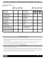 4
4
-
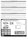 5
5
-
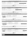 6
6
-
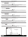 7
7
-
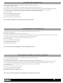 8
8
-
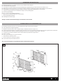 9
9
-
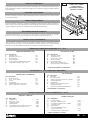 10
10
-
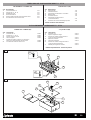 11
11
-
 12
12
-
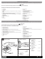 13
13
-
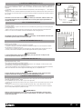 14
14
-
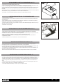 15
15
-
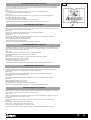 16
16
-
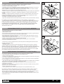 17
17
-
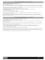 18
18
-
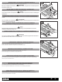 19
19
-
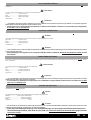 20
20
-
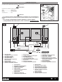 21
21
-
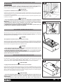 22
22
-
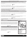 23
23
-
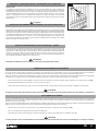 24
24
-
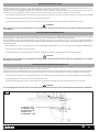 25
25
-
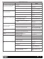 26
26
-
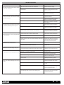 27
27
-
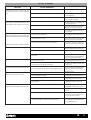 28
28
-
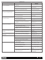 29
29
-
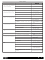 30
30
-
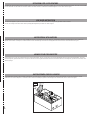 31
31
-
 32
32


Aprimatic ZT 71 Installation Instructions Manual
- Categoria
- Gate Opener
- Tipo
- Installation Instructions Manual
- Questo manuale è adatto anche per
in altre lingue
- English: Aprimatic ZT 71
- français: Aprimatic ZT 71
- español: Aprimatic ZT 71
- Deutsch: Aprimatic ZT 71
Documenti correlati
Altri documenti
-
BFT GIUNO ULTRA BT A20 Manuale del proprietario
-
-
Telcoma CLASSIC-PLUS Manuale del proprietario
-
CAME FROG A Guida d'installazione
-
-
-
Elvox Vimar SW12.T Instructions Sheet
-
CAME A 180 Guida Rapida
-
 RIB PRINCE 24V Manuale utente
-
Genius ROLLER Istruzioni per l'uso
