
Installation Instructions
Console Hammer Shifter
1994-2000 Ford Mustang
Part Number 81001
© B&M Racing & Performance Products LLC 2000
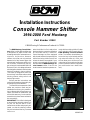
The B&M Mustang Console Ham-
mer shifter is a full ratchet shifter that
is designed to fit 1994 to 2000 Ford
Mustangs with AODE automatic trans-
missions. Unlike other Hammer
shifters, this shifter not only ratchets
between all of the forward gears but
also ratchets into Reverse and Park. It
has a lockout, controlled by the trig-
ger, to keep from unintended shifts into
Reverse or Park. It is designed to work
with the ignition interlock and the brake
interlock installed in these vehicles.
This shifter is designed to work with
the existing Ford shifter cable and the
existing neutral safety switch and
backup light switch.
Please read the instructions and
review the illustrations thoroughly be-
fore beginning the installation.
The mechanical components of this
shifter are precision made and as-
sembled at our factory. Any modifica-
tion or disassembly of these parts can
cause the shifter to malfunction and
will void the warranty. You should dis-
assemble only those items outlined in
the instructions.
IMPORTANT: This shifter is designed
to work with the steering column lock
on your car. Be sure that it is con-
nected to the shifter and properly ad-
justed, so that the steering column
only be locked and the key removed
when the shifter is in Park and so that
the transmission cannot be shifted out
of Park unless the key is turned on.
Some Mustangs are also equipped
with a brake interlock that prevents the
shifter from being shifted out of Park
unless the brakes are applied. If your
vehicle is so equipped, this feature will
also work with the B&M Mustang Con-
sole Hammer shifter. Check to be
certain that the interlock operates cor-
rectly with the existing shifter. If it does
not, it probably will not work with the
B&M Mustang Console Hammer
shifter. The interlock should allow you
to turn the key to the locked position
only when the shifter is in Park, and
will not allow you to shift out of Park
unless the key is turned out of the lock
position (and the brakes are applied if
your vehicle also has a brake inter-
lock).
9500670-01
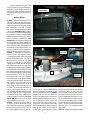
Printed in USA Photo #1
spring clips (two on
each side)
panel
electrical
connectors

The vehicle should be about 2 feet
off the ground for ease of installation.
Use jack stands, wheel ramps or a
vehicle lift. Make sure the vehicle is
firmly supported before attempting to
work on it.
INSTALLATION
STEP 1. Remove the console. First
place the shifter into the Neutral posi-
tion then remove the panel around the
stock shifter by carefully prying up from
the spring clips. It is held in by four
spring clips. Disconnect the electrical
connectors (See Photo #1). Remove
the console compartment underneath
the arm rest. Remove the two screws
hidden under the rubber plugs and pry
up the console compartment (See
Photo #2). Remove the four mounting
screws (two at front of the console and
two under the console compartment)
and set them aside. Set the parking
brake lever to the upright position. Re-
move the console panel and discon-
nect the wiring harness connectors.
STEP 2. From under the car discon-
nect the shifter cable from the shifter.
The end of the cable snaps over a ball
fitting on the shifter lever. This can be
pried off with a screwdriver. The cable
housing is attached to the shifter
flange by two screws. On ‘99-’00 mod-
els, remove the plastic clip holding the
shifter cable. Move the cable end away
from the shifter so that it will not inter-
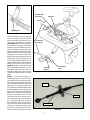
fere with removing the shifter. Inside of
the car, disconnect the interlock cable
from the shifter. This is the 1/4” diam-
eter black cable that goes from the
front of the shifter under the dash board
up to the steering column. Disconnect
the center wire from the plastic
bellcrank by carefully pulling up on it.
It will snap out. Be careful not to bend
the wire. The housing of the interlock
cable is attached to the front of the
shifter base plate with a screw and to
the end of the pivot pin for the inter-
lock bell crank with a clip. Remove both
of these and disconnect the cable (See
Photo #3). Disconnect the electrical
connectors from the shifter.
STEP 3. Remove the stock shifter. It
is held in by four screws that go into
the nuts that are clipped over the edges
of the opening in the tunnel. If any of
the sealing gasket sticks to the tun-
nel, remove it. Peel the paper facing
off of the supplied foam rubber gasket
and stick it to the bottom of the B&M
shifter being sure that the holes line
up. Be sure that the four nuts that are
clipped around the opening in the tun-
nel line up with the holes. Install the
shifter and screw it down with the origi-
nal screws. You will have to work the
right hand edge of the shifter under the
edge of the carpet. (If the original
screws and nuts that hold the shifter
to the tunnel cannot be reused, replace
them with 5/16” X 1” bolts, nuts and
lock washers. Someone will have to
be under the car to hold the nuts while
they are tightened from the top). Screw
the jam nut and the T-handle onto the
end of the shifter stick to make it easier
to shift during the adjustment proce-
dures. The jam nut is a round nut with
two flats on it. The chamfered side
goes down.
STEP 4. Before connecting the shifter
2
Photo #2
rubber plugs &
screws
console
compartment
Photo #3
interlock
housing
clip
plastic
bellcrank
center wire

cable to the shifter, loosen, but do not
remove, the adjusting nut at the front
end of the shifter cable where it con-
nects to the transmission shift lever
(See Figure #1). Move the transmis-
sion shift lever as far back as it will go,
and then move it forward three clicks.
This is the Neutral position. Move the
shifter to the Neutral position. (See the
Operation section at the end of these
instructions). Connect the cable to the
REAR side of the cable bracket on the
shifter using the two self tapping 1/4”
X 5/8” screws provided with the kit. On
‘99-’00 models you will need to use the
adapter and spacer kit as shown in
Photo #4. Snap the cable end over the
ball on the shifter output lever. On ‘99-
’00 models replace the ball with the
cable pin and snap the cable in place.
Tighten the adjusting nut on the shifter
cable.
STEP 5. Check that the shifter is in
the Neutral position. The transmission
should also be in the Neutral position.
With both the shifter and the transmis-
sion in the Neutral position, loosen the
adjusting nut on the transmission shift
lever at the front end of the shifter cable.
Pull forward lightly on the cable to take
up the free play in the cable and then
tighten the nut while still maintaining
tension on the cable. Check that the
shifter will move to all the gear posi-
tions without having to use excessive
force. (See the Operation section at
the end of these instructions). Particu-
larly check that the transmission lever
moves to the Reverse position when
the shifter is moved from Park to Re-
verse. If it does not, recheck the cable
Figure #1
adjusting nut
3
Photo #4
adapter
spacer
shifter cable
Figure #2
cut along
this line
Ford interlock
cable support
nut plate
interlock bell-
crank lever
discard this
piece
screw

adjustment procedure above. If your
shifter cable is well used it may have
developed too much free play to work
with this shifter. In that case you will
need to replace it with a new Ford
cable.
STEP 6. Turn the ignition key to the
unlocked position, one notch clockwise
from the locked position, and put the
shifter into the Park position before
installing the interlock cable. Cut the
end off of the plastic interlock cable
support as shown in Figure #2. Slip
the end of the center wire of the inter-
lock cable into the slot in the interlock
bell crank. Attach the cable support to
the base of the shifter using the sup-
plied socket head 10-24 x 1/2” screw
and nut plate (See Figure #2). Do
not tighten the screw all the way, leave
it loose enough so that the cable will
slide back and forth in the slot.
STEP 7. Pull up the trigger on the
shifter and ratchet it back one posi-
tion into Reverse. Slide the interlock
cable housing as far forward as it will
go and tighten the screw holding the
cable to the shifter. The shifter should
now be able to be shifted to all posi-
tions. The ignition key should not be
able to be turned to the locked posi-
tion and the key removed in any shifter
position except Park. With the key in
the locked position or removed, you
should not be able to pull the trigger
on the shifter up far enough to be able
to shift into reverse. When the key is
turned to the unlock position, the trig-
ger should be able to be pulled up and
the shifter be able to shift into Reverse.
If your car has a brake interlock sys-
tem as well, you will have to apply the
brakes as well as turning the key to
the unlock position to be able to lift
the trigger far enough to shift out of
Park. If the interlock does not operate
correctly, slide the cable backwards
about 1/16” and retry. With small ad-
justments in the position of the cable
you will be able to get the interlock to
operate correctly. Once the interlock
is operating correctly tighten the screw
to keep the cable from moving. You
cannot get to this screw once the con-
sole is installed.
STEP 8. Locate a wire in the console
area that is hot anytime the ignition is
turned on, and is off when the ignition
is off. The power feed to the radio is a
possible choice. This wire will supply
the current for the LED gear position
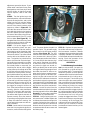
indicator (See Photo #5). The LED
must be illuminated when the ignition
is on, because this is the only indica-
tion of what gear position the shifter is
in. Do not use the wire that was origi-
nally used to illuminate the indicator
on the stock shifter, since this is hot
only when the lights are turned on.
When you identify the hot wire splice
in a length of wire long enough to reach
the shifter plus about 6”. Also run an-
other piece of wire to a good ground.
Be sure the ignition is off when splic-
ing the hot wire and connect the red
wire of the LED indicator to the hot wire
and the black wire to the ground wire.
Check that the LED is illuminated when
the ignition is turned on and the wires
are out of the way of the mechanism.
STEP 9. Locate the wires from the
overdrive switch and splice in the wires
from the new switch on the shifter (See
Photo #5). The wires don’t need to be
connected in any specified order.
STEP 10. Before replacing the con-
sole, remove the T-Handle. Replace the
console and reconnect the wiring to the
console. Replace the four screws that
secure the console to the tunnel and
the dash board. Replace the console
compartment with the two screws and
the rubber plugs.
STEP 11. Replace the panel around
the shifter and reconnect all the elec-
trical connectors. Install the T-Handle
and tighten the jam nut when the handle
is properly oriented. Use a little loctite
on the threads to keep the handle from
turning. Check the operation of the
shifter, indicator and interlock.
OPERATION
The B&M Mustang Console Ham-
mer is a ratchet shifter. You push the
stick forward for up shifts and pull it
back for down shifts. The ratchet shift
allows firm, positive, no-miss upshifts
and downshifts. Move the knob forward
or backwards as far is it will go to se-
lect the next gear. Then let the spring
return the stick to the central position.
After you shift from Drive to Neutral the
reverse lockout prevents the shifter
from shifting any further (to prevent
accidental selection of Reverse). To
shift to Reverse lift the trigger up as far
as it will go and then push the handle
forward and release it. When you shift
from Reverse into Park, the spring
pushes the trigger back down. To shift
out of Park to Reverse or any other gear
it is necessary to lift the trigger first
and then pull back on the handle. From
reverse you can continue to ratchet
backwards to Neutral and any of the
forward gears.
Photo #5
overdrive
wires
LED indicator wires
4
-
 1
1
-
 2
2
-
 3
3
-
 4
4


in altre lingue
Altri documenti
-
Agria 3600 Manuale del proprietario
-
 Aimco Brakes Model 70 Manuale utente
-
Bayliner 1996 Ciera Manuale del proprietario
-
Thrustmaster TH8A SHIFTER Manuale del proprietario
-
-
-
Simplicity 12.5B/38 FORMULA XNL Manuale utente
-
-
-
Thrustmaster TH8A SHIFTER Manuale utente
