
O P E R A T I N G I N S T R U C T I O N
GL6L
Miniature photoelectric sensors


Described product
G6L
GL6L
Manufacturer
SICK AG
Erwin-Sick-Str. 1
79183 Waldkirch
Germany
Production location
SICK Malaysia
Legal information
This work is protected by copyright. Any rights derived from the copyright shall be
reserved for SICK AG. Reproduction of this document or parts of this document is
only permissible within the limits of the legal determination of Copyright Law. Any modi‐
fication, abridgment or translation of this document is prohibited without the express
written permission of SICK AG.
The trademarks stated in this document are the property of their respective owner.
© SICK AG. All rights reserved.
Original document
This document is an original document of SICK AG.
Laser
1
2006/42/EC
NO
SAFETY
8025389.1AR6 / 21.02.2021 | SICK
Subject to change without notice
3

Contents
1 General safety notes......................................................................... 5
2 Notes on UL approval........................................................................ 5
3 Intended use...................................................................................... 5
4 Operating and status indicators...................................................... 6
5 Mounting............................................................................................. 6
6 Electrical installation........................................................................ 6
7 Commissioning.................................................................................. 8
7.1 Alignment.................................................................................................. 8
7.2 Sensing range........................................................................................... 8
7.3 Settings..................................................................................................... 9
8 Troubleshooting................................................................................. 9
9 Disassembly and disposal............................................................... 10
10 Maintenance...................................................................................... 10
11 Technical specifications................................................................... 11
11.1 Dimensional drawing................................................................................ 12
11.2 Light spot diagram.................................................................................... 12
CONTENTS
4
8025389.1AR6 / 21.02.2021 | SICK
Subject to change without notice

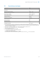
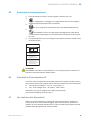
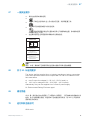
1 General safety notes
■
Read the operating instructions before commissioning.
■
Connection, mounting, and configuration may only be performed by trained
specialists.
■
2006/42/EC
NO
SAFETY
Not a safety component in accordance with the EU Machinery Directive.
■
Do not install the sensor at locations that are exposed to direct sunlight
or other weather influences, unless this is expressly permitted in the operating
instructions.
■
These operating instructions contain information required during the life cycle of
the sensor.
EN/IEC 60825-1:2014
IEC60825-1:2007
LASER CLASS 1
Laser
1
Maximum pulse power < 5.95 mW
Puls length: 2 µs
Wavelength: 670 - 690 nm
Complies with FDA performance
standards except for conformance with
IEC 60825-1 Ed. 3,
as described in Laser Notice No. 56,
dated May 8, 2019
ATTENTION
WARNING: Interruption, manipulation or incorrect use can lead to hazardous exposure
due to laser radiation.
2 Notes on UL approval
The device shall be supplied from an isolating transformer having a secondary overcur‐
rent protective device that complies with UL 248 to be installed in the field rated either:
a) max 5 amps for voltages 0 ~ 20 V (0 ~ 28.3 V peak), or
b) 100 / Vp for voltages of 20 ~ 30 V (28.3 ~ 42.4 V peak).
Alternatively, they can be supplied from a Class 2 power supply.
UL Environmental Rating: Enclosure type 1
3 Intended use
The GL6L is an opto-electronic photoelectric retro-reflective sensor (referred to as “sen‐
sor” in the following) for the optical, non-contact detection of objects. A reflector is
required for this product to function. If the product is used for any other purpose or
modified in any way, any warranty claim against SICK AG shall become void.
GENERAL SAFETY NOTES 1
8025389.1AR6 / 21.02.2021 | SICK
Subject to change without notice
5

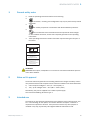
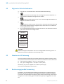
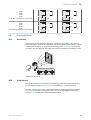
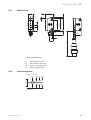
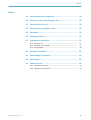
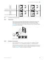
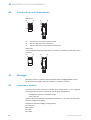
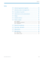
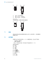
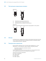
4 Operating and status indicators
GL6L-xxx1x
1
2 3
23
1
1
Potentiometer: sensitivity adjustment
2
LED indicator yellow: status of received light beam
3
LED indicator green: supply voltage active
GL6L-xxx3x
Sensor which it is not possible to set: The sensor is adjusted and ready for operation.
2 3
23
5 Mounting
Mount the sensor and the reflector using suitable mounting brackets (see the SICK
range of accessories). Align the sensor and reflector with each other.
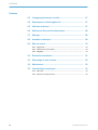
6 Electrical installation
The sensors must be connected in a voltage-free state (U
V
= 0 V). The following informa‐
tion must be observed depending on the connection type:
– Plug connection: pin assignment
– Cable: wire color
Only apply voltage/switch on the voltage supply (U
V
> 0 V) once all electrical connec‐
tions have been established.
Explanation of connection terminology:
BN = Brown
WH = White
BU = Blue
BK = Black
n. c. = no connection
4 OPERATING AND STATUS INDICATORS
6
8025389.1AR6 / 21.02.2021 | SICK
Subject to change without notice

Q = switching output 1
Q = switching output 2
L+ = supply voltage (Uv)
M = common
L.ON = light operate
D.ON = dark operate
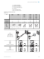
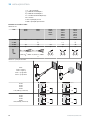
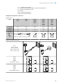
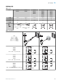
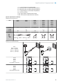
Connection and Output detail:
Table 1: DC
GL6L -P1xxx
-N1xxx
-E2xxx
-F2xxx
-P3xxx
-N3xxx
-P5xxx
-N5xxx
-P4xxx
-N4xxx
-P6xxx
-N6xxx
-P7xxx
-N7xxx
-E4xxx
-F4xxx
-E6xxx
-F6xxx
-E7xxx
-F7xxx
1 = BN + (L+) + (L+) + (L+) + (L+) + (L+)
2 = WH -
Q
- n. c.
Q
3 = BU - (M) - (M) - (M) - (M) - (M)
4 = BK Q Q Q Q Q
0.205 mm
2
/
AWG24
0.205 mm
2
/
AWG24
1
4
3
2
1
4
3
2
1
4
3
Table 2: Output Operation
GL6L
-Pxxxx = Q output
-Nxxxx = Q output
-Fxxxx = Q + Q output
-Exxxx = Q + Q output
-Px1xx
-Px2xx
-Px5xx
-Px6xx
L.ON, PNP: Q (≤ 100 mA)
+ (L+)
Q
‒ (M)
Load
+ (L+)
Q
‒ (M)
Load
-Px1xx
-Px2xx
-Px3xx
-Px4xx
D.ON, PNP: Q (≤ 100 mA)
+ (L+)
Q
‒ (M)
Load
+ (L+)
Q
‒ (M)
Load
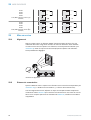
-Nx1xx
-Nx2xx
-Nx5xx
-Nx6xx
L.ON, NPN Open Collector Q (≤ 100 mA)
+ (L+)
Q
‒ (M)
+ (L+)
Q
‒ (M)
Load
+ (L+)
Q
‒ (M)
Load
ELECTRICAL INSTALLATION 6
8025389.1AR6 / 21.02.2021 | SICK
Subject to change without notice
7

-Nx1xx
-Nx2xx
-Nx3xx
-Nx4xx
D.ON, NPN Open Collector Q (≤ 100 mA)
+ (L+)
Q
‒ (M)
Load
+ (L+)
Q
‒ (M)
+ (L+)
Q
‒ (M)
Load
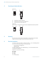
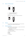
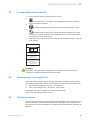
7 Commissioning
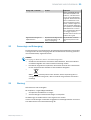
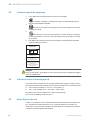
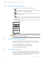
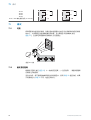
7.1 Alignment
Align the sensor with a suitable reflector. Select the position so that the red emitted
light beam hits the center of the reflector. The sensor must have a clear view of the
reflector, with no object in the path of the beam [see figure 1]. You must ensure that the
optical openings of the sensor and reflector are completely clear.
Figure 1: Alignment
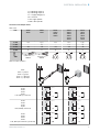
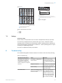
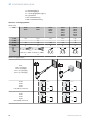
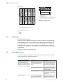
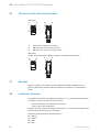
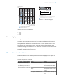
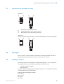
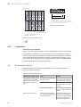
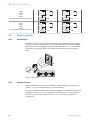
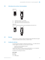
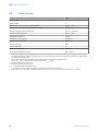
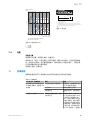
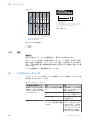
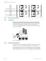
7.2 Sensing range
Adjust the distance between the sensor and the reflector according to the correspond‐
ing diagram [see figure 2] (x = sensing range, y = operating reserve).
After alignment is complete, move a non-transparent object into the path of the beam.
Use table 2 to check the function. If the switching output fails to behave in accordance
with table 2, check the application conditions.
7 COMMISSIONING
8
8025389.1AR6 / 21.02.2021 | SICK
Subject to change without notice

100
10
1
Operating reserve
Distance in m (feet)
0 2
(6.56)
4
(13.12)
6
(19.69)
8
(26.25)
10
(32.81)
12
(39.37)
21 3
Recommended sensing range for
the best performance
Figure 2: Characteristic curve GL6L
1
2
3
Distance in m (feet)
0 2
(6.56)
4
(13.12)
6
(19.69)
8
(26.25)
10
(32.81)
12
(39.37)
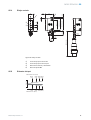
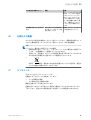
0.08 5.54.5
0.08 1210
0.08 86.5
A = Sensing range min. in m
B = Sensing range max. in m
C = Maximum distance range from reflector to sensor (operating reserve 1)
D = Recommended distance range from reflector to sensor (operating reserve 2)
D
A
B
C
Recommended sensing range for the best performance
Figure 3: Bar graph
1
PL10F
2
PL20F
3
P250F
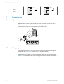
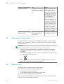
7.3 Settings
Sensitivity setting
Sensor which it is not possible to set: The sensor is adjusted and ready for operation.
The sensitivity is adjusted with the potentiometer (type: 5-turn). Clockwise rotation:
operating reserve increased; counterclockwise rotation: operating reserve reduced. We
recommend setting the potentiometer to “Maximum”. A lower operating reserve may be
necessary for depolarizing surfaces.
The sensor is adjusted and ready for operation.
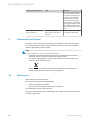
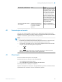
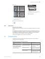
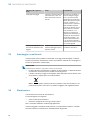
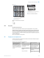
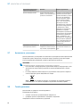
8 Troubleshooting
The Troubleshooting table indicates measures to be taken if the sensor stops working.
Table 3: Troubleshooting
LED indicator/fault pattern Cause Measures
Yellow LED does not light up
even though the light beam
is aligned to the reflector and
there is no object in the path of
the beam
No voltage or voltage below
the limit values
Check the power supply,
check all electrical connec‐
tions (cables and plug connec‐
tions)
Voltage interruptions Ensure there is a stable power
supply without interruptions
Sensor is faulty If the power supply is OK,
replace the sensor
Yellow LED flashes Sensor is still ready for oper‐
ation, but the operating condi‐
tions are not ideal
Check the operating condi‐
tions: Fully align the beam
of light (light spot) with the
reflector. / Clean the optical
surfaces (sensor and reflec‐
tor) / If the potentiometer is
set to the max. sensitivity:
COMMISSIONING 7
8025389.1AR6 / 21.02.2021 | SICK
Subject to change without notice
9

LED indicator/fault pattern Cause Measures
Reduce the distance between
the sensor and the reflector,
and check the reflector type /
Reflector is not suitable for
the application in question
(we recommend only using
SICK reflectors) / Check sens‐
ing range and adjust if neces‐
sary / Distance between the
sensor and the reflector is too
long
Signal interruptions when
object is detected
Depolarizing property of the
object surface (e.g., tape),
reflection
Reduce sensitivity or change
the position of the sensor
9 Disassembly and disposal
The sensor must be disposed of according to the applicable country-specific regula‐
tions. Efforts should be made during the disposal process to recycle the constituent
materials (particularly precious metals).
NOTE
Disposal of batteries, electric and electronic devices
•
According to international directives, batteries, accumulators and electrical or
electronic devices must not be disposed of in general waste.
•
The owner is obliged by law to return this devices at the end of their life to the
respective public collection points.
•
WEEE: This symbol on the product, its package or in this document,
indicates that a product is subject to these regulations.
10 Maintenance
SICK sensors are maintenance-free.
We recommend doing the following regularly:
•
Clean the external lens surfaces
•
Check the screw connections and plug-in connections
No modifications may be made to devices.
Subject to change without notice. Specified product properties and technical data are
not written guarantees.
9 DISASSEMBLY AND DISPOSAL
10
8025389.1AR6 / 21.02.2021 | SICK
Subject to change without notice

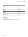
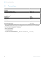
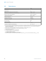
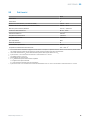
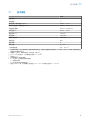
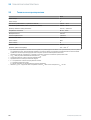
11 Technical specifications
GL6L
Laser class 1
Laser class 1
1)
Sensing range (with reflector P250F) 0.08 m ... 10 m
Sensing range max. (with reflector P250F) 0.08 m ... 12 m
Light spot diameter/distance 3.5 mm / 1,000 mm
Supply voltage U
B
DC 10 ... 30 V
2)
Output current I
max.
100 mA
3)
Switching frequency 1,000 Hz
4)
Max. response time 0.625 ms
5)
Enclosure rating IP67
Protection class III
Circuit protection A, C, D
6)
Ambient operating temperature -20 ... +50 °C
7)
1)
We recommend using compound triangular reflectors or reflective tape to ensure reliable operation. Suitable reflectors and foils can be
found in the SICK accessories range. Use of reflectors with large-scale triple structures can negatively influence functionality.
2)
Limit values. U
B
connections reverse-polarity protected. Residual ripple max 5 V
PP
3)
As of U
B
> 24 V, a max. load current I
max.
= 50 mA is permitted.
4)
With light / dark ratio 1:1
5)
Signal transit time with resistive load
6)
A = U
B
-connections reverse polarity protected
C = Interference suppression
D = outputs overcurrent and short-circuit protected
7)
As of T
a
≥ 45 °C, a max. supply voltage U
B
= 24 V and a max. load current I
max.
= 50 mA is permitted.
TECHNICAL SPECIFICATIONS 11
8025389.1AR6 / 21.02.2021 | SICK
Subject to change without notice
11

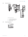
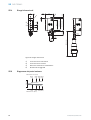
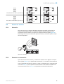
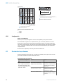
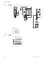
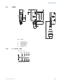
11.1 Dimensional drawing
6.3
(0.25)
0.5
(0.02)
21
(0.83)
0.5
(0.02)
9.7
(0.38)
3
(0.12)
11.5
(0.45)
31.5 (1.24)
28.5 (1.12)
25.4 (1.00)
2.3
(0.09)
18.3
(0.72)
305 (12.01)
9.7
(0.38)
12
(0.47)
1
2
4
4
3
Figure 4: Dimensional drawing
1
Center of optical axis, sender
2
Center of optical axis, receiver
3
Operating and status indicators
4
M3 threaded mounting hole
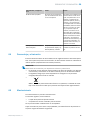
11.2 Light spot diagram
Sensor
Ø 28
(1.10)
Ø 3.5
(0.14)
Ø 58
(2.28)
Ø 70
(2.76)
1
(3.28)
5
(16.40)
10
(32.81)
12
(39.37)
Distance in m (feet)
Diameter in mm (inch)
11 TECHNICAL SPECIFICATIONS
12
8025389.1AR6 / 21.02.2021 | SICK
Subject to change without notice


Beschriebenes Produkt
G6L
GL6L
Hersteller
SICK AG
Erwin-Sick-Str. 1
79183 Waldkirch
Deutschland
Fertigungsstandort
SICK Malaysia
Rechtliche Hinweise
Dieses Werk ist urheberrechtlich geschützt. Die dadurch begründeten Rechte bleiben
bei der Firma SICK AG. Die Vervielfältigung des Werks oder von Teilen dieses Werks
ist nur in den Grenzen der gesetzlichen Bestimmungen des Urheberrechtsgesetzes
zulässig. Jede Änderung, Kürzung oder Übersetzung des Werks ohne ausdrückliche
schriftliche Zustimmung der Firma SICK AG ist untersagt.
Die in diesem Dokument genannten Marken sind Eigentum ihrer jeweiligen Inhaber.
© SICK AG. Alle Rechte vorbehalten.
Originaldokument
Dieses Dokument ist ein Originaldokument der SICK AG.
Laser
1
2006/42/EC
NO
SAFETY
14
8025389.1AR6 / 21.02.2021 | SICK
Subject to change without notice

Inhalt
12 Allgemeine Sicherheitshinweise..................................................... 16
13 Hinweise zur UL Zulassung.............................................................. 16
14 Bestimmungsgemäße Verwendung............................................... 16
15 Betriebs- und Statusanzeigen.......................................................... 17
16 Montage.............................................................................................. 17
17 Elektrische Installation..................................................................... 17
18 Inbetriebnahme................................................................................. 19
18.1 Ausrichtung............................................................................................... 19
18.2 Schaltabstand........................................................................................... 19
18.3 Einstellungen............................................................................................. 20
19 Störungsbehebung............................................................................ 20
20 Demontage und Entsorgung............................................................ 21
21 Wartung.............................................................................................. 21
22 Technische Daten.............................................................................. 22
22.1 Maßzeichnung........................................................................................... 23
22.2 Lichtfleckdiagramm.................................................................................. 23
INHALT
8025389.1AR6 / 21.02.2021 | SICK
Subject to change without notice
15

12 Allgemeine Sicherheitshinweise
■
Lesen Sie vor der Inbetriebnahme des Geräts die Betriebsanleitung.
■
Der Anschluss, die Montage und die Konfiguration des Geräts dürfen nur
von geschultem Fachpersonal vorgenommen werden.
■
2006/42/EC
NO
SAFETY
Bei diesem Gerät handelt es sich um kein sicherheitsgerichtetes Bauteil im
Sinne der EU-Maschinenrichtlinie.
■
Installieren Sie den Sensor nicht an Orten, die direkter Sonneneinstrahlung
oder sonstigen Wettereinflüssen ausgesetzt sind, ausser dies ist in der Betriebs‐
anleitung ausdrücklich erlaubt.
■
Die vorliegende Betriebsanleitung enthält Informationen, die während des Lebens‐
zyklus der Lichtschranke benötigt werden.
EN/IEC 60825-1:2014
IEC60825-1:2007
LASERKLASSE 1
Laser
1
Maximale Pulsleistung: < 5,95 mW
Impulsdauer: 2 µs
Wellenlänge: 670 - 690 nm
Entspricht den FDA
Leistungsstandards mit Ausnahme der
Konformität mit IEC 60825-1, Ed. 3
wie im Laserhinweis Nr. 56 vom
08.05.2019 beschrieben
ACHTUNG
WARNUNG: Eingriffe, Manipulation oder eine unsachgemäße Verwendung können zu
gefährlicher Exposition gegenüber Laserstrahlung führen.
13 Hinweise zur UL Zulassung
The device shall be supplied from an isolating transformer having a secondary overcur‐
rent protective device that complies with UL 248 to be installed in the field rated either:
a) max 5 amps for voltages 0 ~ 20 V (0 ~ 28.3 V peak), or
b) 100 / Vp for voltages of 20 ~ 30 V (28.3 ~ 42.4 V peak).
Alternatively, they can be supplied from a Class 2 power supply.
UL Environmental Rating: Enclosure type 1
14 Bestimmungsgemäße Verwendung
Die GL6L ist eine optoelektronische Reflexions-Lichtschranke (im Folgenden Sensor
genannt) und wird zum optischen, berührungslosen Erfassen von Sachen eingesetzt.
Zur Funktion wird ein Reflektor benötigt. Bei jeder anderen Verwendung und bei Verän‐
derungen am Produkt verfällt jeglicher Gewährleistungsanspruch gegenüber der SICK
AG.
12 ALLGEMEINE SICHERHEITSHINWEISE
16
8025389.1AR6 / 21.02.2021 | SICK
Subject to change without notice

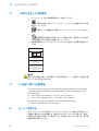
15 Betriebs- und Statusanzeigen
GL6L-xxx1x
1
2 3
23
1
1
Potentiometer: Einstellung der Empfindlichkeit
2
Anzeige-LED gelb: Status Lichtempfang
3
Anzeige-LED grün: Versorgungsspannung aktiv
GL6L-xxx3x
Sensor ohne Einstellmöglichkeit: Sensor ist eingestellt und betriebsbereit.
2 3
23
16 Montage
Sensor und Reflektor an geeignete Befestigungswinkel montieren (siehe SICK-Zube‐
hör-Programm). Sensor und Reflektor zueinander ausrichten.
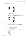
17 Elektrische Installation
Anschluss der Sensoren muss spannungsfrei (U
V
= 0 V) erfolgen. Je nach Anschlussart
sind die folgenden Informationen zu beachten:
– Steckeranschluss: Anschlussbelegung
– Leitung: Aderfarbe
Erst nach Anschluss aller elektrischen Verbindungen die Spannungsversorgung (U
V
> 0 V) anlegen bzw. einschalten.
Erläuterung der Anschlussterminologie:
BN = braun
WH = weiß
BU = blau
BK = schwarz
n. c. = unbeschaltet
BETRIEBS- UND STATUSANZEIGEN 15
8025389.1AR6 / 21.02.2021 | SICK
Subject to change without notice
17

Q = Schaltausgang 1
Q = Schaltausgang 2
L+ = Versorgungsspannung (Uv)
M = gemeinsam
L.ON = Hellauswertung
D.ON = Dunkelauswertung
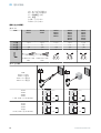
Anschluss- und Ausgangsdetails:
Tabelle 4: DC
GL6L -P1xxx
-N1xxx
-E2xxx
-F2xxx
-P3xxx
-N3xxx
-P5xxx
-N5xxx
-P4xxx
-N4xxx
-P6xxx
-N6xxx
-P7xxx
-N7xxx
-E4xxx
-F4xxx
-E6xxx
-F6xxx
-E7xxx
-F7xxx
1 = BN + (L+) + (L+) + (L+) + (L+) + (L+)
2 = WH -
Q
- n. c.
Q
3 = BU - (M) - (M) - (M) - (M) - (M)
4 = BK Q Q Q Q Q
0,205 mm
2
/ AWG2
4
0,205 mm
2
/ AWG2
4
1
4
3
2
1
4
3
2
1
4
3
Tabelle 5: Ausgangsfunktion
GL6L
-Pxxxx = Q-Ausgang
-Nxxxx = Q-Ausgang
-Fxxxx = Q + Q Ausgang
-Exxxx = Q + Q Ausgang
-Px1xx
-Px2xx
-Px5xx
-Px6xx
L.ON, PNP: Q (≤ 100 mA)
+ (L+)
Q
‒ (M)
Load
+ (L+)
Q
‒ (M)
Load
-Px1xx
-Px2xx
-Px3xx
-Px4xx
D.ON, PNP: Q (≤ 100 mA)
+ (L+)
Q
‒ (M)
Load
+ (L+)
Q
‒ (M)
Load
17 ELEKTRISCHE INSTALLATION
18
8025389.1AR6 / 21.02.2021 | SICK
Subject to change without notice

-Nx1xx
-Nx2xx
-Nx5xx
-Nx6xx
L.ON, NPN Open Collector Q (≤ 100 mA)
+ (L+)
Q
‒ (M)
+ (L+)
Q
‒ (M)
Load
+ (L+)
Q
‒ (M)
Load
-Nx1xx
-Nx2xx
-Nx3xx
-Nx4xx
D.ON, NPN Open Collector Q (≤ 100 mA)
+ (L+)
Q
‒ (M)
Load
+ (L+)
Q
‒ (M)
+ (L+)
Q
‒ (M)
Load
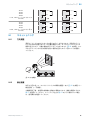
18 Inbetriebnahme
18.1 Ausrichtung
Sensor auf geeigneten Reflektor ausrichten. Positionierung so wählen, dass der rote
Sendelichtstrahl in der Mitte des Reflektors auftrifft. Die Lichtschranke muss freie Sicht
auf den Reflektor haben, ohne Objekte im Strahlweg [siehe Abbildung 5]. Es ist darauf
zu achten, dass die optischen Öffnungen von Sensor und Reflektor vollständig frei sind.
Abbildung 5: Ausrichtung
18.2 Schaltabstand
Den Abstand zwischen Lichtschranke und Reflektor gemäß dem entsprechenden Dia‐
gramm anpassen [siehe Abbildung 6] (x = Schaltabstand, y = Funktionsreserve).
Nach der Ausrichtung ein nicht transparentes Objekt im Strahlweg platzieren. Mithilfe
von Tabelle 5 die Funktion überprüfen. Wenn sich der Schaltausgang nicht entspre‐
chend Tabelle 5 verhält, die Einsatzbedingungen prüfen.
INBETRIEBNAHME 18
8025389.1AR6 / 21.02.2021 | SICK
Subject to change without notice
19

100
10
1
Funktionsreserve
Abstand in m
0 2 4 6 8 10 12
21 3
Empfohlener Schaltabstandsbereich für
beste Performance
Abbildung 6: Kennlinie GL6L
1
2
3
0 2 4 6 8 10 12
0,08 5,54,5
0,08 1210
0,08 86,5
Abstand in mm
A = Schaltabstand min. in m
B = Schaltabstand max. in m
C = Abstandsbereich Reflektor zu Sensor max. (Funktionsreserve 1)
D = Abstandsbereich Reflektor zu Sensor empfohlen (Funktionsreserve 2)
D
A
B
C
Empfohlener Schaltabstandsbereich für beste Performance
Abbildung 7: Balkenanzeige
1
PL10F
2
PL20F
3
P250F
18.3 Einstellungen
Empfindlichkeitseinstellung
Sensor, der nicht eingestellt werden kann: Der Sensor ist justiert und betriebsbereit.
Die Empfindlichkeit wird mit dem Potentiometer eingestellt (Typ: 5 Drehungen). Dre‐
hung im Uhrzeigersinn: Funktionsreserve erhöht; Drehung gegen den Uhrzeigersinn:
Funktionsreserve verringert. Es wird empfohlen, das Potentiometer auf „Maximum“
einzustellen. Bei depolarisierenden Oberflächen kann eine geringere Funktionsreserve
notwendig sein.
Der Sensor ist justiert und betriebsbereit.
19 Störungsbehebung
Tabelle Störungsbehebung zeigt, welche Maßnahmen durchzuführen sind, wenn die
Funktion des Sensors nicht mehr gegeben ist.
Tabelle 6: Fehlerbehebung
Anzeige-LED / Fehlerbild Ursache Maßnahme
gelbe LED leuchtet nicht,
obwohl der Lichtstrahl auf den
Reflektor ausgerichtet ist und
kein Objekt im Strahlengang ist
keine Spannung oder Span‐
nung unterhalb der Grenz‐
werte
Spannungsversorgung prüfen,
den gesamten elektrischen
Anschluss prüfen (Leitungen
und Steckerverbindungen)
Spannungsunterbrechungen Sicherstellen einer stabilen
Spannungsversorgung ohne
Unterbrechungen
Sensor ist defekt Wenn Spannungsversorgung
in Ordnung ist, dann Sensor
austauschen
gelbe LED blinkt Sensor ist noch betriebsbe‐
reit, aber die Betriebsbedin‐
gungen sind nicht optimal
Betriebsbedingungen prüfen:
Lichtstrahl (Lichtfleck) voll‐
ständig auf den Reflektor aus‐
18 INBETRIEBNAHME
20
8025389.1AR6 / 21.02.2021 | SICK
Subject to change without notice
La pagina si sta caricando...
La pagina si sta caricando...
La pagina si sta caricando...
La pagina si sta caricando...
La pagina si sta caricando...
La pagina si sta caricando...
La pagina si sta caricando...
La pagina si sta caricando...
La pagina si sta caricando...
La pagina si sta caricando...
La pagina si sta caricando...
La pagina si sta caricando...
La pagina si sta caricando...
La pagina si sta caricando...
La pagina si sta caricando...
La pagina si sta caricando...
La pagina si sta caricando...
La pagina si sta caricando...
La pagina si sta caricando...
La pagina si sta caricando...
La pagina si sta caricando...
La pagina si sta caricando...
La pagina si sta caricando...
La pagina si sta caricando...
La pagina si sta caricando...
La pagina si sta caricando...
La pagina si sta caricando...
La pagina si sta caricando...
La pagina si sta caricando...
La pagina si sta caricando...
La pagina si sta caricando...
La pagina si sta caricando...
La pagina si sta caricando...
La pagina si sta caricando...
La pagina si sta caricando...
La pagina si sta caricando...
La pagina si sta caricando...
La pagina si sta caricando...
La pagina si sta caricando...
La pagina si sta caricando...
La pagina si sta caricando...
La pagina si sta caricando...
La pagina si sta caricando...
La pagina si sta caricando...
La pagina si sta caricando...
La pagina si sta caricando...
La pagina si sta caricando...
La pagina si sta caricando...
La pagina si sta caricando...
La pagina si sta caricando...
La pagina si sta caricando...
La pagina si sta caricando...
La pagina si sta caricando...
La pagina si sta caricando...
La pagina si sta caricando...
La pagina si sta caricando...
La pagina si sta caricando...
La pagina si sta caricando...
La pagina si sta caricando...
La pagina si sta caricando...
La pagina si sta caricando...
La pagina si sta caricando...
La pagina si sta caricando...
La pagina si sta caricando...
La pagina si sta caricando...
La pagina si sta caricando...
La pagina si sta caricando...
La pagina si sta caricando...
La pagina si sta caricando...
La pagina si sta caricando...
La pagina si sta caricando...
La pagina si sta caricando...
La pagina si sta caricando...
La pagina si sta caricando...
La pagina si sta caricando...
La pagina si sta caricando...
La pagina si sta caricando...
La pagina si sta caricando...
La pagina si sta caricando...
La pagina si sta caricando...
La pagina si sta caricando...
La pagina si sta caricando...
-
 1
1
-
 2
2
-
 3
3
-
 4
4
-
 5
5
-
 6
6
-
 7
7
-
 8
8
-
 9
9
-
 10
10
-
 11
11
-
 12
12
-
 13
13
-
 14
14
-
 15
15
-
 16
16
-
 17
17
-
 18
18
-
 19
19
-
 20
20
-
 21
21
-
 22
22
-
 23
23
-
 24
24
-
 25
25
-
 26
26
-
 27
27
-
 28
28
-
 29
29
-
 30
30
-
 31
31
-
 32
32
-
 33
33
-
 34
34
-
 35
35
-
 36
36
-
 37
37
-
 38
38
-
 39
39
-
 40
40
-
 41
41
-
 42
42
-
 43
43
-
 44
44
-
 45
45
-
 46
46
-
 47
47
-
 48
48
-
 49
49
-
 50
50
-
 51
51
-
 52
52
-
 53
53
-
 54
54
-
 55
55
-
 56
56
-
 57
57
-
 58
58
-
 59
59
-
 60
60
-
 61
61
-
 62
62
-
 63
63
-
 64
64
-
 65
65
-
 66
66
-
 67
67
-
 68
68
-
 69
69
-
 70
70
-
 71
71
-
 72
72
-
 73
73
-
 74
74
-
 75
75
-
 76
76
-
 77
77
-
 78
78
-
 79
79
-
 80
80
-
 81
81
-
 82
82
-
 83
83
-
 84
84
-
 85
85
-
 86
86
-
 87
87
-
 88
88
-
 89
89
-
 90
90
-
 91
91
-
 92
92
-
 93
93
-
 94
94
-
 95
95
-
 96
96
-
 97
97
-
 98
98
-
 99
99
-
 100
100
-
 101
101
-
 102
102


in altre lingue
- English: SICK GL6L Operating instructions
- français: SICK GL6L Mode d'emploi
- español: SICK GL6L Instrucciones de operación
- Deutsch: SICK GL6L Bedienungsanleitung
- русский: SICK GL6L Инструкция по эксплуатации
- português: SICK GL6L Instruções de operação
- 日本語: SICK GL6L 取扱説明書
Documenti correlati
-
SICK GL6L Istruzioni per l'uso
-
-
-
SICK GSE6L Istruzioni per l'uso
-
-
-
-
-
-