Yamaha MD 8 Manuale utente
- Categoria
- Strumenti musicali
- Tipo
- Manuale utente
Questo manuale è adatto anche per

MULTITRACK MD RECORDER
Owner’s Manual
E
MULTITRACK MD RECORDER
GROUP 1
CH 1 CH 2 CH 3 CH 4 CH 5 CH 6 CH 7 CH 8
2345678
REC SELECT
DISPLAY
REPEAT MARK SEARCH MARK
AUTO
PUNCH I/O SONG SEARCH PAUSE
REHE REC PLAY STOP
A B LAST REC SEARCH SET EXIT
ADJUSTPITCH EDIT UTILITY
ENTER
PHONES PUNCH I/O
DATA
+ –
CURSOR
1
1
2
3
4
2 1 2
3 4 3 4
GROUP ASSIGN GROUP ASSIGN
1 3
2 4
GROUP
2TR IN
MONITOR
SELECT
CUE MIX
TO STEREO
CUE
MASTER
GROUP
MASTER
STEREO
CUE
010 010
010
010
010
010
010
MONITOR
LEVEL
MIN MAX
9-10
LINE
GAIN
HIGH
MID
LOW
AUX
PAN
MIC
LR
8
8 STEREO
11-12
10
9
8
7
6
5
4
3
2
1
0
10
9
8
7
6
5
4
3
2
1
0
10
9
8
7
6
5
4
3
2
1
0
–15 +15
–15 +15
–15 +15
250 5k
FLIP
CUE
010
F
G
1
010
2
010
1 2
3 4
GROUP ASSIGN
L
ODD
R
EVEN
LINE
GAIN
HIGH
MID
LOW
AUX
PAN
MIC
LR
7
7
10
9
8
7
6
5
4
3
2
1
0
–15 +15
–15 +15
–15 +15
250 5k
FLIP
CUE
010
F
G
1
010
2
010
1 2
3 4
GROUP ASSIGN
L
ODD
R
EVEN
LINE
GAIN
HIGH
MID
LOW
AUX
PAN
MIC
LR
6
6
10
9
8
7
6
5
4
3
2
1
0
–15 +15
–15 +15
–15 +15
250 5k
FLIP
CUE
010
F
G
1
010
2
010
1 2
3 4
GROUP ASSIGN
L
ODD
R
EVEN
LINE
GAIN
HIGH
MID
LOW
AUX
PAN
MIC
LR
5
5
10
9
8
7
6
5
4
3
2
1
0
–15 +15
–15 +15
–15 +15
250 5k
FLIP
CUE
010
F
G
1
010
2
010
1 2
3 4
GROUP ASSIGN
L
ODD
R
EVEN
LINE
GAIN
HIGH
MID
LOW
AUX
PAN
MIC
LR
4
4
10
9
8
7
6
5
4
3
2
1
0
–15 +15
–15 +15
–15 +15
250 5k
FLIP
CUE
010
F
G
1
010
2
010
1 2
3 4
GROUP ASSIGN
L
ODD
R
EVEN
LINE
GAIN
HIGH
MID
LOW
AUX
PAN
MIC
LR
3
3
10
9
8
7
6
5
4
3
2
1
0
–15 +15
–15 +15
–15 +15
250 5k
FLIP
CUE
010
F
G
1
010
2
010
1 2
3 4
GROUP ASSIGN
L
ODD
R
EVEN
LINE
GAIN
HIGH
MID
LOW
AUX
PAN
MIC
LR
2
2
10
9
8
7
6
5
4
3
2
1
0
–15 +15
–15 +15
–15 +15
250 5k
FLIP
CUE
010
F
G
1
010
2
010
1 2
3 4
GROUP ASSIGN
L
ODD
R
EVEN
LINE
GAIN
HIGH
MID
LOW
AUX
PAN
MIC
LR
1
1
10
9
8
7
6
5
4
3
2
1
0
–15 +15
–15 +15
–15 +15
250 5k
FLIP
PB MIC/
LINE
CUE
010
F
G
1
010
2
010
1 2
3 4
GROUP ASSIGN
L
ODD
R
EVEN
P
A
N
L
E
V
E
L
PB MIC/
LINE
P
A
N
L
E
V
E
L
PB MIC/
LINE
P
A
N
L
E
V
E
L
PB MIC/
LINE
P
A
N
L
E
V
E
L
PB MIC/
LINE
P
A
N
L
E
V
E
L
PB MIC/
LINE
P
A
N
L
E
V
E
L
PB MIC/
LINE
P
A
N
L
E
V
E
L
PB MIC/
LINE
P
A
N
L
E
V
E
L
MIC/LINE INPUT LINE INPUT AUX SEND
1 2 345678 9101112 1 2INSERT I/O INSERT I/O
12341234
TOC WRITE
IN OUT

Laser Diode Properties
* Material : GaAlAs
* Wavelength : 780–790 nm
* Emission Duration : Continuous
* Laser Output Power : Less than 44.6 µW
Laser output is measured at a
distance of 20cm from the object
lens on the optical pick-up head.
(Note)
This unit is classified as a
Class 1 laser product.
The CLASS 1 LASER
PRODUCT label is located on
the exterior.
CLASS 1 LASER PRODUCT
Klassmärkning för Finland.
CLASS 1 LASER PRODUCT
LUOKAN 1 LASERLAITE
KLASS 1 LASERAPPARAT
ADVARSEL
Usynlig laserstråling ved åbning. Undgå udsaettelse
for stråling.
VAROITUS
Laitteen käyttäminen muulla kuin tässä käyttöohjeesa
mainitulla tavalla saattaa altistaa käyttäjän
turvallisuusluokan 1 ylittävälle näkymättömälle
lasersäteilylle.
VARNING
Om apparaten används på annat sätt än i denna
bruksanvisning specificerats, kan användaren utsättas
för osynlig laserstrålning, som överskrider gränsen för
laserklass 1.
CAUTION
USE OF CONTROLS OR ADJUSTMENTS OR
PERFORMANCE OF PROCEDURES OTHER
THAN THOSE SPECIFIED HEREIN MAY RESULT
IN HAZARDOUS RADIATION EXPOSURE.
•This label is not placed on USA
model and Canadian model.
•This label is placed on the lid.
•Varningsanvisning för
laserstrålning. Placerad i
apparaten.
CAUTION : INVISIBLE LASER RADIATION WHEN OPEN AND INTRLOCKS DEFEATED.
DO NOT STARE INTO BEAM OR VIEW DIRECTLY WITH OPTICAL INSTRUMENTS.
VARNING : OSYNLIG LASERSTRÅLNING NÄR DENNA DEL ÄR ÖPPNAD OCH SPÄRRAR
ÄR URKOPPLADE. STIRRA EJ IN I STRÅLEN OCH BETRAKTA EJ STRÅLEN MED
OPISKA INSTRUMENT.
VARO! : NÄKYMÄTÖNTÄ AVATTAESSA JA SUOJALUKITUS OHITETTAESSA OLET
ALTTIINA LASERSÄTEILYLLE. ÄLÄ TUIJOTA SÄTEESEEN ÄLÄKÄ KATSO SITÄ
OPTISEN LAITTEEN LÄPI.
FCC INFORMATION (U.S.A.)
1. IMPORTANT NOTICE: DO NOT MODIFY THIS UNIT!
This product, when installed as indicated in the instructions contained in this
manual, meets FCC requirements. Modifications not expressly approved by
Yamaha may void your authority, granted by the FCC, to use the product.
2. IMPORTANT: When connecting this product to accessories and/or another
product use only high quality shielded cables. Cable/s supplied with this product
MUST be used. Follow all installation instructions. Failure to follow instructions
could void your FCC authorization to use this product in the USA.
3. NOTE: This product has been tested and found to comply with the requirements
listed in FCC Regulations, Part 15 for Class “B” digital devices. Compliance
with these requirements provides a reasonable level of assurance that your use of
this product in a residential environment will not result in harmful interference
with other electronic devices. This equipment generates/uses radio frequencies
and, if not installed and used according to the instructions found in the users
manual, may cause interference harmful to the operation of other electronic
devices. Compliance with FCC regulations does not guarantee that interference
will not occur in all installations. If this product is found to be the source of
interference, which can be determined by turning the unit “OFF” and “ON”,
please try to eliminate the problem by using one of the following measures:
Relocate either this product or the device that is being affected by the
interference.
Utilize power outlets that are on different branch (circuit breaker or fuse)
circuits or install AC line filter/s.
In the case of radio or TV interference, relocate/reorient the antenna. If the
antenna lead-in is 300 ohm ribbon lead, change the lead-in to coaxial type cable.
If these corrective measures do not produce satisfactory results, please contact
the local retailer authorized to distribute this type of product. If you can not
locate the appropriate retailer, please contact Yamaha Corporation of America,
Electronic Service Division, 6600 Orangethorpe Ave, Buena Park, CA 90620
IMPORTANT NOTICE FOR
THE UNITED KINGDOM
Connecting the Plug and Cord
IMPORTANT: The wires in this mains lead are coloured in accordance
with the following code:
BLUE : NEUTRAL
BROWN : LIVE
As the colours of the wires in the mains lead of this apparatus may not
correspond with the coloured markings identifying the terminals in your
plug proceed as follows:
The wire which is coloured BLUE must be connected to the terminal
which is marked with the letter N or coloured BLACK.
The wire which is coloured BROWN must be connected to the terminal
which is marked with the letter L or coloured RED.
Making sure that neither core is connected to the earth terminal of the
three pin plug.
IMPORTANT
Please record the serial number of this unit in the space below.
Serial No.:
The serial number is located on the bottom of the unit.
Retain this Owner's Manual in a safe place for future reference.

• Explanation of Graphical Symbols
The exclamation point within an equilat-
eral triangle is intended to alert the user to
the presence of important operating and
maintenance (servicing) instructions in the
literature accompanying the product.
The lightning flash with arrowhead symbol
within an equilateral triangle is intended to
alert the user to the presence of uninsulated
“dangerous voltage” within the product’s
enclosure that may be of sufficient magni-
tude to constitute a risk of electric shock to
persons.
10. Power Sources — The appliance should be connected to a
power supply only of the type described in the operating
instructions or as marked on the appliance.
11. Grounding or Polarization — The precautions that should be
taken so that the grounding or polarization means of an
appliance is not defeated.
12. Power-Cord Protection — Power-supply cords should be
routed so that they are not likely to be walked on or pinched by
items placed upon or against them, paying particular attention
to cords at plugs, convenience receptacles, and the point where
they exit from the appliance.
13. Cleaning — The appliance should be cleaned only as recom-
mended by the manufacturer.
14. Nonuse Periods — The power cord of the appliance should be
unplugged from the outlet when left unused for a long period
of time.
15. Object and Liquid Entry — Care should be taken so that
objects do not fall and liquids are not spilled into the enclosure
through openings.
16. Damage Requiring Service — The appliance should be ser-
viced by qualified service personnel when:
A. The power-supply cord or the plug has been damaged; or
B. Objects have fallen, or liquid has been spilled into the
appliance; or
C. The appliance has been exposed to rain; or
D. The appliance does not appear to operate normally or
exhibits a marked change in performance; or
E. The appliance has been dropped, or the enclosure dam-
aged.
17. Servicing — The user should not attempt service the appliance
beyond that described in the operating instructions.
SAFETY INSTRUCTIONS
CAUTION: TO REDUCE THE RISK OF
ELECTRIC SHOCK, DO NOT REMOVE
COVER (OR BACK). NO USER-SERVICEABLE
PARTS INSIDE. REFER SERVICING TO
QUALIFIED SERVICE PERSONNEL.
SEE BOTTOM OF ENCLOSURE FOR GRAPHIC
SYMBOLS MARKING.
CAUTION
RISK OF ELECTRIC SHOCK
DO NOT OPEN
1. Read Instructions — All the safety and operating instructions
should be read before the appliance is operated.
2. Retain Instructions — The safety and operating instructions
should be retained for future reference.
3. Heed Warnings — All warnings on the appliance and in the
operating instructions should be adhered to.
4. Follow Instructions — All operating and use instructions
should be followed.
5. Water and Moisture — The appliance should not be used near
water – for example, near a bathtub, washbowl, kitchen sink,
laundry tub, in a wet basement, or near a swimming pool, and
the like.
6. Carts and Stands — The appliance
should be used only with a cart or stand
that is recommended by the manufac-
turer.
6A An appliance and cart combination
should be moved with care. Quick
stops, excessive force, and uneven
surfaces may cause the appliance and cart combination to
overturn.
7. Wall or Ceiling Mounting — The appliance should be mounted
to a wall or ceiling only as recommended by the manufacturer.
8. Ventilation — The appliance should be situated so that its
location or position does not interfere with its proper ventila-
tion. For example, the appliance should not be situated on a
bed, sofa, rug, or similar surface that may block the ventilation
openings; or, placed in a built-in installation, such as a
bookcase or cabinet that may impede the flow of air through
the ventilation openings.
9. Heat — The appliance should be situated away from heat
sources such as radiators, heat registers, stoves, or other
appliances (including amplifiers) that produce heat.

ii
MD8—Owner’s Manual
Important
Read the Following Before Operating the MD8
Warnings
• Do not locate the MD8 in a place subject to excessive heat or direct sunlight. This could
be a fire hazard.
• Do not place MD8 in a place subject to excessive humidity or dust. This could be a fire
or electrical shock hazard.
• Connect the supplied AC power cord only to an AC outlet of the type stated in this
Owner’s Manual
or as marked on the MD8. Failure to do so is a fire and electrical shock
hazard.
• Do not plug several devices into the same AC outlet. This may overload the AC outlet,
and can be a fire and electrical shock hazard. It may also affect the performance of some
devices.
• Do not place heavy objects on the power cord. A damaged power cord is a potential fire
and electrical shock hazard.
• If the power cord is damaged (i.e., cut or a bare wire is exposed), ask your dealer for a
replacement. Using the MD8 in this condition is a fire and shock hazard.
• Hold the AC power cord plug when disconnecting from an AC outlet. Never pull the
cord. Damaging the power cord in this way is a potential fire and electrical shock hazard.
• Do not place small metal objects on top of the MD8. Metal objects inside the MD8 are a
fire and electrical shock hazard.
• Do not block the MD8 ventilation holes above and behind the disc compartment. These
vents are to prevent the internal temperature from rising. Blocked vents are a fire hazard.
• Do not try to modify the MD8. This could be a fire and electrical shock hazard.
• The MD8 operating temperature is between 5˚C and 35˚C (41˚F and 95˚F).
Cautions
• Turn off all audio devices and speakers when connecting to the MD8. Refer to the
owner’s manual for each device. Use the correct cables and connect as specified.
• The MD8 is a precision device. Handle it with care.
• Handle MD DATA discs with care.
• If you notice any abnormality—such as smoke, odor, or noise—turn off the MD8
immediately, remove the AC power cord from the AC outlet, confirm that the abnormal-
ity is no longer present, and then consult your dealer for repair. Using the MD8 in this
condition is a fire and shock hazard.
• If a foreign object or water gets inside the MD8, turn it off immediately, remove the AC
power cord from the AC outlet, and then consult your dealer for repair. Using the MD8
in this condition is a fire and electrical shock hazard.
• If you plan not to use the MD8 for a long period of time (such as when you are on vaca-
tion), remove the AC power cord from the AC outlet. Leaving the MD8 connected is a
fire hazard.
• Do not use benzene, thinner, cleaning detergent, or a chemical cloth to clean the MD8.
Use a soft, dry cloth.

iii
MD8—Owner’s Manual
Ventilation
Allow a distance of 10 cm between the unit and the wall so that heat generated from the unit
will be released effectively. Also, allow enough space between the unit and other devices. If
you mount the unit in an audio rack, keep a space of 10 cm to the side panel. Remove the
rear panel of the rack or open a vent hole. If heat release is inadequate, the unit will retain
heat inside the unit, which may cause a fire.
Interference
The MD8 uses high-frequency digital circuits that may cause interference on radios and tele-
visions placed close to it. If interference does occur, relocate the affected equipment.
Copyright
© 1997 Yamaha Corporation. All rights reserved.
No part of the MD8 software or this
Owner’s Manual
may be reproduced or distributed in
any form or by any means without the prior written authorization of Yamaha Corporation.
Trademarks
MD DATA and MiniDisc are trademarks of Sony Corporation.
US and foreign patents licensed from Dolby Laboratories Licensing Corporation.
All other trademarks are the property of their respective holders.
Package Contents
The MD8 package should contain the following items. Make sure that you have them all.
• MD8 Multitrack MD Recorder
• AC power cord
• This Owner’s Manual
Contact your Yamaha dealer if something is missing.
Keep This Manual For Future Reference

iv
MD8—Owner’s Manual
Contents
1. Welcome to the MD8 . . . . . . . . . . . . . . . . 1
MD8 Features . . . . . . . . . . . . . . . . . . . . . . . . . . . . . . . . . . . . . . . . . . . . . . . . . . 1
Mixer . . . . . . . . . . . . . . . . . . . . . . . . . . . . . . . . . . . . . . . . . . . . . . . . . . . . 1
Recorder . . . . . . . . . . . . . . . . . . . . . . . . . . . . . . . . . . . . . . . . . . . . . . . . . 1
Buying Discs for the MD8 . . . . . . . . . . . . . . . . . . . . . . . . . . . . . . . . . . . . . . . . 3
MD8 TOC . . . . . . . . . . . . . . . . . . . . . . . . . . . . . . . . . . . . . . . . . . . . . . . . . . . . . 3
2. Touring the MD8 . . . . . . . . . . . . . . . . . . . . 4
Topside View . . . . . . . . . . . . . . . . . . . . . . . . . . . . . . . . . . . . . . . . . . . . . . . . . . . 4
Input Channels . . . . . . . . . . . . . . . . . . . . . . . . . . . . . . . . . . . . . . . . . . . . . . . . . 5
Master Section . . . . . . . . . . . . . . . . . . . . . . . . . . . . . . . . . . . . . . . . . . . . . . . . . . 7
Display . . . . . . . . . . . . . . . . . . . . . . . . . . . . . . . . . . . . . . . . . . . . . . . . . . . . . . . . 8
Disc Transport Section . . . . . . . . . . . . . . . . . . . . . . . . . . . . . . . . . . . . . . . . . . . 10
Rear Panel . . . . . . . . . . . . . . . . . . . . . . . . . . . . . . . . . . . . . . . . . . . . . . . . . . . . . 12
Front Connectors . . . . . . . . . . . . . . . . . . . . . . . . . . . . . . . . . . . . . . . . . . . . . . . 15
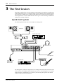
3. The First Session . . . . . . . . . . . . . . . . . . . 16
Quick-Start System . . . . . . . . . . . . . . . . . . . . . . . . . . . . . . . . . . . . . . . . . . . . . . 16
Connecting the Power Cord . . . . . . . . . . . . . . . . . . . . . . . . . . . . . . . . . . . . . . . 17
Turning on the MD8 . . . . . . . . . . . . . . . . . . . . . . . . . . . . . . . . . . . . . . . . . . . . 17
Loading a Disc . . . . . . . . . . . . . . . . . . . . . . . . . . . . . . . . . . . . . . . . . . . . . . . . . . 17
Recording the First Track . . . . . . . . . . . . . . . . . . . . . . . . . . . . . . . . . . . . . . . . . 17
Making the Connections (GRP & DIR) . . . . . . . . . . . . . . . . . . . . . . . . 18
GRP Method . . . . . . . . . . . . . . . . . . . . . . . . . . . . . . . . . . . . . . . . . . . . . 18
DIR Method . . . . . . . . . . . . . . . . . . . . . . . . . . . . . . . . . . . . . . . . . . . . . . 19
Monitoring & Recording (GRP & DIR) . . . . . . . . . . . . . . . . . . . . . . . 19
Listening to the First Track . . . . . . . . . . . . . . . . . . . . . . . . . . . . . . . . . . 19
Overdubbing . . . . . . . . . . . . . . . . . . . . . . . . . . . . . . . . . . . . . . . . . . . . . . . . . . . 20
Mixdown . . . . . . . . . . . . . . . . . . . . . . . . . . . . . . . . . . . . . . . . . . . . . . . . . . . . . . 21
An Overview of Multitrack Recording . . . . . . . . . . . . . . . . . . . . . . . . . . . . . . 22
Basic Multitracking . . . . . . . . . . . . . . . . . . . . . . . . . . . . . . . . . . . . . . . . 22
Advanced Multitracking . . . . . . . . . . . . . . . . . . . . . . . . . . . . . . . . . . . . 22
About Monitoring . . . . . . . . . . . . . . . . . . . . . . . . . . . . . . . . . . . . . . . . . . . . . . . 23
Multi-Source Mixing . . . . . . . . . . . . . . . . . . . . . . . . . . . . . . . . . . . . . . . . . . . . 24
4. Recording & Mixing Techniques . . . . . . . 26
Recording a New Song . . . . . . . . . . . . . . . . . . . . . . . . . . . . . . . . . . . . . . . . . . . 26
Searching for Blanks . . . . . . . . . . . . . . . . . . . . . . . . . . . . . . . . . . . . . . . 26
Setting the Recording Mode . . . . . . . . . . . . . . . . . . . . . . . . . . . . . . . . . 27
Recording . . . . . . . . . . . . . . . . . . . . . . . . . . . . . . . . . . . . . . . . . . . . . . . . 28
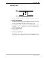
Titling Discs & Songs . . . . . . . . . . . . . . . . . . . . . . . . . . . . . . . . . . . . . . . . . . . . 28
Manual Punch In/Out . . . . . . . . . . . . . . . . . . . . . . . . . . . . . . . . . . . . . . . . . . . 29
Using the REC Button . . . . . . . . . . . . . . . . . . . . . . . . . . . . . . . . . . . . . . 29
Using the REC SELECT buttons . . . . . . . . . . . . . . . . . . . . . . . . . . . . . 30
Using a Footswitch . . . . . . . . . . . . . . . . . . . . . . . . . . . . . . . . . . . . . . . . 31
Auto Punch In/Out . . . . . . . . . . . . . . . . . . . . . . . . . . . . . . . . . . . . . . . . . . . . . . 32
Setting the In/Out Points “On-the-Fly” . . . . . . . . . . . . . . . . . . . . . . . 32
Single Take Auto Punch In/Out . . . . . . . . . . . . . . . . . . . . . . . . . . . . . . 34
Multi Take Auto Punch In/Out . . . . . . . . . . . . . . . . . . . . . . . . . . . . . . 37
Setting the Pre-Roll & Post-Roll Times . . . . . . . . . . . . . . . . . . . . . . . . 40

v
MD8—Owner’s Manual
Ping-Pong Recording . . . . . . . . . . . . . . . . . . . . . . . . . . . . . . . . . . . . . . . . . . . 41
Preparing for Ping-Pong . . . . . . . . . . . . . . . . . . . . . . . . . . . . . . . . . . . 42
Rehearsing Ping-Pong . . . . . . . . . . . . . . . . . . . . . . . . . . . . . . . . . . . . . 43
Performing Ping-Pong for Real . . . . . . . . . . . . . . . . . . . . . . . . . . . . . 43
Checking the Ping-Pong Operation . . . . . . . . . . . . . . . . . . . . . . . . . . 43
Ping-Pong with Overdub . . . . . . . . . . . . . . . . . . . . . . . . . . . . . . . . . . . . . . . . 44
Pitch . . . . . . . . . . . . . . . . . . . . . . . . . . . . . . . . . . . . . . . . . . . . . . . . . . . . . . . . . 46
Adjusting the Pitch . . . . . . . . . . . . . . . . . . . . . . . . . . . . . . . . . . . . . . . . 46
Toggling Between FIX & VARI Pitch . . . . . . . . . . . . . . . . . . . . . . . . . 46
Using a Footswitch . . . . . . . . . . . . . . . . . . . . . . . . . . . . . . . . . . . . . . . . . . . . . 47
Applying Effects . . . . . . . . . . . . . . . . . . . . . . . . . . . . . . . . . . . . . . . . . . . . . . . . 48
Applying Effects at Mixdown . . . . . . . . . . . . . . . . . . . . . . . . . . . . . . . . . . . . . 48
Applying Effects when Recording . . . . . . . . . . . . . . . . . . . . . . . . . . . . . . . . . 49
Applying Effects with Ping-Pong . . . . . . . . . . . . . . . . . . . . . . . . . . . . . . . . . . 49
Patching in Signal Processors . . . . . . . . . . . . . . . . . . . . . . . . . . . . . . . . . . . . . 50
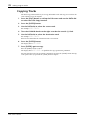
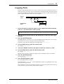
5. Quick Search Functions . . . . . . . . . . . . . . 51
Searching for Songs . . . . . . . . . . . . . . . . . . . . . . . . . . . . . . . . . . . . . . . . . . . . . 51
Rewind & Fast Forward . . . . . . . . . . . . . . . . . . . . . . . . . . . . . . . . . . . . . . . . . . 51
Shuttle Playback Function (Cue/Review) . . . . . . . . . . . . . . . . . . . . . 51
Locating Specific Points . . . . . . . . . . . . . . . . . . . . . . . . . . . . . . . . . . . . 52
Searching for the Last Rec IN & OUT Points . . . . . . . . . . . . . . . . . . . . . . . . 52
Searching for Markers . . . . . . . . . . . . . . . . . . . . . . . . . . . . . . . . . . . . . . . . . . . 53
Inserting Markers . . . . . . . . . . . . . . . . . . . . . . . . . . . . . . . . . . . . . . . . . . . . . . 53
Marker Indicators . . . . . . . . . . . . . . . . . . . . . . . . . . . . . . . . . . . . . . . . 53
Adjusting Markers . . . . . . . . . . . . . . . . . . . . . . . . . . . . . . . . . . . . . . . . . . . . . . 54
Erasing Markers . . . . . . . . . . . . . . . . . . . . . . . . . . . . . . . . . . . . . . . . . . . . . . . . 56
6. Repeat, Cue List & Program Play . . . . . . 57
One Song Repeat . . . . . . . . . . . . . . . . . . . . . . . . . . . . . . . . . . . . . . . . . . . . . . . 57
All Song Repeat . . . . . . . . . . . . . . . . . . . . . . . . . . . . . . . . . . . . . . . . . . . . . . . . 57
A–B Repeat . . . . . . . . . . . . . . . . . . . . . . . . . . . . . . . . . . . . . . . . . . . . . . . . . . . . 58
Cue List Playback & Copy . . . . . . . . . . . . . . . . . . . . . . . . . . . . . . . . . . . . . . . . 59
Program Playback . . . . . . . . . . . . . . . . . . . . . . . . . . . . . . . . . . . . . . . . . . . . . . 60
7. Editing Songs & Tracks . . . . . . . . . . . . . . 61
Viewing Disc Contents . . . . . . . . . . . . . . . . . . . . . . . . . . . . . . . . . . . . . . . . . . 61
Erasing Discs . . . . . . . . . . . . . . . . . . . . . . . . . . . . . . . . . . . . . . . . . . . . . . . . . . 62
Copying & Converting Songs . . . . . . . . . . . . . . . . . . . . . . . . . . . . . . . . . . . . . 62
Renumbering Songs . . . . . . . . . . . . . . . . . . . . . . . . . . . . . . . . . . . . . . . . . . . . 64
Moving Songs . . . . . . . . . . . . . . . . . . . . . . . . . . . . . . . . . . . . . . . . . . . . . . . . . . 65
Dividing Songs . . . . . . . . . . . . . . . . . . . . . . . . . . . . . . . . . . . . . . . . . . . . . . . . . 66
Combining Songs . . . . . . . . . . . . . . . . . . . . . . . . . . . . . . . . . . . . . . . . . . . . . . 67
Erasing Songs . . . . . . . . . . . . . . . . . . . . . . . . . . . . . . . . . . . . . . . . . . . . . . . . . . 68
Erasing Tracks . . . . . . . . . . . . . . . . . . . . . . . . . . . . . . . . . . . . . . . . . . . . . . . . . 68
Erasing Parts . . . . . . . . . . . . . . . . . . . . . . . . . . . . . . . . . . . . . . . . . . . . . . . . . . . 69
Copying Tracks . . . . . . . . . . . . . . . . . . . . . . . . . . . . . . . . . . . . . . . . . . . . . . . . 70
Copying Parts . . . . . . . . . . . . . . . . . . . . . . . . . . . . . . . . . . . . . . . . . . . . . . . . . . 71
8. Other Functions . . . . . . . . . . . . . . . . . . . 72
Frame Display . . . . . . . . . . . . . . . . . . . . . . . . . . . . . . . . . . . . . . . . . . . . . . . . . 72
Display Dimmer . . . . . . . . . . . . . . . . . . . . . . . . . . . . . . . . . . . . . . . . . . . . . . . . 72
Peak Hold . . . . . . . . . . . . . . . . . . . . . . . . . . . . . . . . . . . . . . . . . . . . . . . . . . . . . 72

vi
MD8—Owner’s Manual
9. The MD8 & MIDI . . . . . . . . . . . . . . . . . . . 73
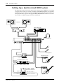
Using the MD8 in a Synchronized MIDI System . . . . . . . . . . . . . . . . . . . . . . 73
About Tempo Maps . . . . . . . . . . . . . . . . . . . . . . . . . . . . . . . . . . . . . . . . . . . . . 73
Setting Up a Synchronized MIDI System . . . . . . . . . . . . . . . . . . . . . . . . . . . . 74
Using MTC . . . . . . . . . . . . . . . . . . . . . . . . . . . . . . . . . . . . . . . . . . . . . . . . . . . . 75
Setting the MD8 for MTC Operation . . . . . . . . . . . . . . . . . . . . . . . . . 75
Setting the MIDI Sequencer . . . . . . . . . . . . . . . . . . . . . . . . . . . . . . . . . 75
MTC Cabling Note . . . . . . . . . . . . . . . . . . . . . . . . . . . . . . . . . . . . . . . . 75
Using MIDI Clock . . . . . . . . . . . . . . . . . . . . . . . . . . . . . . . . . . . . . . . . . . . . . . . 76
Setting the MIDI Sequencer . . . . . . . . . . . . . . . . . . . . . . . . . . . . . . . . . 76
Programming the Tempo Map . . . . . . . . . . . . . . . . . . . . . . . . . . . . . . . 76
Selecting MIDI Clock for synchronization . . . . . . . . . . . . . . . . . . . . . 79
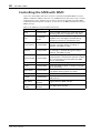
Controlling the MD8 with MMC . . . . . . . . . . . . . . . . . . . . . . . . . . . . . . . . . . 80
Setting the MMC Device ID . . . . . . . . . . . . . . . . . . . . . . . . . . . . . . . . . 81
Enabling MMC . . . . . . . . . . . . . . . . . . . . . . . . . . . . . . . . . . . . . . . . . . . 81
Tempo Map Chart . . . . . . . . . . . . . . . . . . . . . . . . . . . . . . . . . . . . . . . . . . . . . . 82
10. MD8 Applications . . . . . . . . . . . . . . . . . 83
One-Take Recording . . . . . . . . . . . . . . . . . . . . . . . . . . . . . . . . . . . . . . . . . . . . . 83
MIDI Home Studio . . . . . . . . . . . . . . . . . . . . . . . . . . . . . . . . . . . . . . . . . . . . . . 84
Using the MD8 with Another Mixer . . . . . . . . . . . . . . . . . . . . . . . . . . . . . . . . 85
Track transfer . . . . . . . . . . . . . . . . . . . . . . . . . . . . . . . . . . . . . . . . . . . . . . . . . . 85
11. Beyond the Basics . . . . . . . . . . . . . . . . . 86
Effects Return . . . . . . . . . . . . . . . . . . . . . . . . . . . . . . . . . . . . . . . . . . . . . . . . . . 86
EQ . . . . . . . . . . . . . . . . . . . . . . . . . . . . . . . . . . . . . . . . . . . . . . . . . . . . . . . . . . . . 86
Markers . . . . . . . . . . . . . . . . . . . . . . . . . . . . . . . . . . . . . . . . . . . . . . . . . . . . . . . 86
Pitch Applications . . . . . . . . . . . . . . . . . . . . . . . . . . . . . . . . . . . . . . . . . . . . . . . 87
Monitoring . . . . . . . . . . . . . . . . . . . . . . . . . . . . . . . . . . . . . . . . . . . . . . . . . . . . 87
Mixdown . . . . . . . . . . . . . . . . . . . . . . . . . . . . . . . . . . . . . . . . . . . . . . . . . . . . . . 88
12. Q&A Section . . . . . . . . . . . . . . . . . . . . . 89
Troubleshooting . . . . . . . . . . . . . . . . . . . . . 91
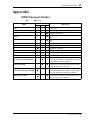
Appendix . . . . . . . . . . . . . . . . . . . . . . . . . . . 93
MD8 Transport Modes . . . . . . . . . . . . . . . . . . . . . . . . . . . . . . . . . . . . . . . . . . . 93
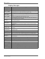
Display Messages . . . . . . . . . . . . . . . . . . . . . . . . . . . . . . . . . . . . . . . . . . . . . . . . 94
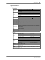
Specifications . . . . . . . . . . . . . . . . . . . . . . . . . . . . . . . . . . . . . . . . . . . . . . . . . . . 95
Recorder . . . . . . . . . . . . . . . . . . . . . . . . . . . . . . . . . . . . . . . . . . . . . . . . . 95
Mixer . . . . . . . . . . . . . . . . . . . . . . . . . . . . . . . . . . . . . . . . . . . . . . . . . . . . 95
General . . . . . . . . . . . . . . . . . . . . . . . . . . . . . . . . . . . . . . . . . . . . . . . . . . 96
Block Diagram . . . . . . . . . . . . . . . . . . . . . . . . . . . . . . . . . . . . . . . . . . . . . . . . . . 97
Dimensions . . . . . . . . . . . . . . . . . . . . . . . . . . . . . . . . . . . . . . . . . . . . . . . . . . . . 98
Glossary . . . . . . . . . . . . . . . . . . . . . . . . . . . . 99
Index . . . . . . . . . . . . . . . . . . . . . . . . . . . . . . 102
MIDI Implementation Chart . . End of Manual

Welcome to the MD8
1
MD8—Owner’s Manual
1
Welcome to the MD8
Thank you for choosing the Yamaha MD8 Multitrack MD Recorder. The MD8 uses the
MiniDisc format for 8-track multitrack recording, with superior sound quality and quick
search capabilities.
To take best advantage of your MD8, read this
Owner’s Manual
thoroughly.
MD8 Features
Mixer
The mixer section features eight mono input channels, two stereo inputs, and four groups.
• Input channels 1 through 8 feature phone jack MIC/LINE inputs and continuously vari-
able GAIN controls, which can handle both microphone and line-level signals with ease.
• Input channels 1 and 2 also have XLR-type inputs, switchable +48 V phantom powering
(for use with condenser microphones), and inserts for patching external processors.
• Musical three-band EQ (High, Mid, Low) with sweepable mid on input channels 1
through 8 offers flexible tone-shaping capabilities.
• Two AUX Sends for use with external effects processors.
• Dedicated Cue level and pan controls on input channels 1 through 8 mean that cue sig-
nals can be monitored in stereo or used as additional inputs.
• Channel FLIP switches flip the channel and cue signal source between MIC/LINE input
(recording) and disc track (mixdown).
• The CUE MIX TO STEREO switch provides eight extra sources in addition to the eight
tracks for a total of 20 inputs during mixdown.
• 2TR IN connection for confidence monitoring and playback with a master recorder.
• Flexible monitoring of group, CUE, stereo bus, or 2TR IN.
• Track direct outputs for connection to another mixer.
Recorder
The recorder section features an 8-track recorder based on the MD DATA audio format,
which has several advantages over tape-based multitrackers. With a tape-based recorder, for
example, you have to keep at least one track free for ping-pong. With the MD8, however,
you can record on all eight tracks and then ping-pong (i.e., eight-track playback with
ping-pong). This is because the MD8 can simultaneously play and record on the same track,
providing greater creative freedom when planing tracks. Although the MD8 uses a 4-group
mixer, up to eight tracks can be recorded simultaneously by assigning the input channel sig-
nals directly to the tracks.
• Four recording modes: MONO, 2TR, 4TR, and 8TR.
• Recording times of 18 minutes for 8TR, 37 minutes for 4TR, 74 minutes for 2TR, and
148 minutes for MONO.
• Mono or 2-track recording and playback with regular audio MiniDiscs.
• Ping-pong even when all eight tracks have been recorded.
• Superior sound quality and negligible sound degradation after repeated overdubs and
ping-pong operations.
• Zero wow and flutter and pitch fluctuation.

2
Welcome to the MD8
MD8—Owner’s Manual
• The convenient MD DATA disc medium requires no formatting before use, and when a
project is complete, simply pop in a new disc and start tracking straightaway.
• Quick location of song start, song end, last recording in/out points, and up to 10 user
mark points per song.
• Precise punch in/out with 11-millisecond accuracy.
• Auto punch in/out with multiple-take record and select capability (choose the best from
up to 99 takes).
• Song editing functions include: Copy, Move, Divide, Combine, Renumber, and Erase.
Track editing functions include: Copy, Erase, Part Copy, and Part Erase.
• Songs recorded on the Yamaha MD4 Recorder can be converted to MD8-compatible
8-track songs by using the Copy function, with the option to reorder, erase, or duplicate
tracks.
• Disc and song titling for easy identification.
• Repeat modes include One Song, All Song, A-B, and Auto Punch Rehearse.
• Cue and review at 0.5x 2x, 4x, 8x, 16x, or 32x playback speed (0.5x cue only).
• Variable pitch of approximately
±
12%.
• Clear FLD (Fluorescent Display) shows signal levels, mode, status, and Total, Remain-
ing, or Elapsed times, or measures and beats when the MIDI tempo map is used.
• MTC (MIDI Timecode) or MIDI Clock (with Tempo Map) output for synchronization
within a MIDI-based system.
• MMC (MIDI Machine Control) for remote MD8 control.
• Jog and shuttle dial for ease of operation.
For some quick answers about the MD8, see the
Q&A Section
on page 89.

Buying Discs for the MD8
3
MD8—Owner’s Manual
Buying Discs for the MD8
It’s important that you buy the correct type of disc for use with your MD8. For 8-track
recording and playback, you must use MD DATA discs. Regular MiniDiscs can only be used
for 2-track recording and playback (2TR mode).
MD DATA discs are used as a storage media for computers. The MD8 uses the MD DATA
audio format to store data on them. Regular MiniDiscs are also referred to as MD discs,
although they are used only for music.
New MD DATA discs do not require formatting before use with the MD8. Discs that have
been used to store computer data, however, must first be formatted. See
Erasing Discs
on
page 62.
Regular MiniDisc decks cannot play MD DATA discs.
Regular MiniDiscs recorded on the MD8 can be played on a regular MiniDisc deck.
MiniDisc recordings made on a regular MiniDisc deck can be edited on the MD8. MiniDiscs
containing songs that were digitally copied from a commercial CD, however, cannot be
edited due to the SCMS (Serial Copy Management System) protection system.
MD8 TOC
TOC refers to the Table Of Contents area on a disc. The TOC contains information about
what is recorded on the disc, the disc title, song titles, and so on. The TOC EDIT indicator
lights up when the TOC needs to be updated, usually after a new recording or edit. You must
update the TOC before ejecting a disc or turning off the MD8. It’s also a good idea to update
the TOC at regular intervals just in case of a power failure. Failure to update the TOC can
result in data being lost. For example, if you record something but do not update the TOC,
your data will be lost if the MD8 is inadvertently turned off, the power cord accidentally dis-
connected, or a power failure occurs.
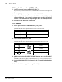
Type Logo Description
MD DATA
MD DATA discs are for computer data storage
applications. You can purchase them at com-
puter stores. This is the type of disc you should
buy for 8-track recording and playback with your
MD8. Note that there are two types available:
playback only
and
rewritable
. Buy the rewritable
type.
MiniDisc
MiniDiscs are used only for music. Two types are
available:
playback only
and
recordable
. The MD8
can record up to two tracks on the
recordable
type and play the
playback only
type.
Note:
If you press the EJECT button while TOC EDIT is shown on the display, the disc
will not eject. Press [TOC WRITE] (STOP) to update the TOC, and then eject the disc.

4
Touring the MD8
MD8—Owner’s Manual
2
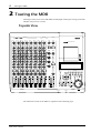
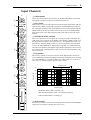
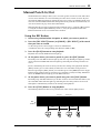
Touring the MD8
This chapter takes you on a tour of the MD8, identifying the various parts to help you become
familiar with your new recorder.
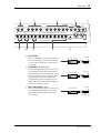
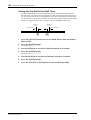
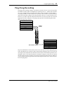
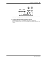
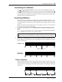
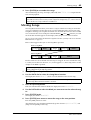
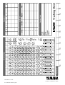
Topside View
The individual sections of the MD8 are explained on the following pages.
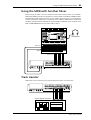
MULTITRACK MD RECORDER
GROUP 1
CH 1 CH 2 CH 3 CH 4 CH 5 CH 6 CH 7 CH 8
2345678
REC SELECT
DISPLAY
REPEAT MARK SEARCH MARK
AUTO
PUNCH I/O SONG SEARCH PAUSE
REHE REC PLAY STOP
A B LAST REC SEARCH SET EXIT
ADJUSTPITCH EDIT UTILITY
ENTER
PHONES PUNCH I/O
DATA
+ –
CURSOR
1
1
2
3
4
2 1 2
3 4 3 4
GROUP ASSIGN GROUP ASSIGN
1 3
2 4
GROUP
2TR IN
MONITOR
SELECT
CUE MIX
TO STEREO
CUE
MASTER
GROUP
MASTER
STEREO
CUE
010 010
010
010
010
010
010
MONITOR
LEVEL
MIN MAX
9-10
LINE
GAIN
HIGH
MID
LOW
AUX
PAN
MIC
LR
8
8 STEREO
11-12
10
9
8
7
6
5
4
3
2
1
0
10
9
8
7
6
5
4
3
2
1
0
10
9
8
7
6
5
4
3
2
1
0
–15 +15
–15 +15
–15 +15
250 5k
FLIP
CUE
010
F
G
1
010
2
010
1 2
3 4
GROUP ASSIGN
L
ODD
R
EVEN
LINE
GAIN
HIGH
MID
LOW
AUX
PAN
MIC
LR
7
7
10
9
8
7
6
5
4
3
2
1
0
–15 +15
–15 +15
–15 +15
250 5k
FLIP
CUE
010
F
G
1
010
2
010
1 2
3 4
GROUP ASSIGN
L
ODD
R
EVEN
LINE
GAIN
HIGH
MID
LOW
AUX
PAN
MIC
LR
6
6
10
9
8
7
6
5
4
3
2
1
0
–15 +15
–15 +15
–15 +15
250 5k
FLIP
CUE
010
F
G
1
010
2
010
1 2
3 4
GROUP ASSIGN
L
ODD
R
EVEN
LINE
GAIN
HIGH
MID
LOW
AUX
PAN
MIC
LR
5
5
10
9
8
7
6
5
4
3
2
1
0
–15 +15
–15 +15
–15 +15
250 5k
FLIP
CUE
010
F
G
1
010
2
010
1 2
3 4
GROUP ASSIGN
L
ODD
R
EVEN
LINE
GAIN
HIGH
MID
LOW
AUX
PAN
MIC
LR
4
4
10
9
8
7
6
5
4
3
2
1
0
–15 +15
–15 +15
–15 +15
250 5k
FLIP
CUE
010
F
G
1
010
2
010
1 2
3 4
GROUP ASSIGN
L
ODD
R
EVEN
LINE
GAIN
HIGH
MID
LOW
AUX
PAN
MIC
LR
3
3
10
9
8
7
6
5
4
3
2
1
0
–15 +15
–15 +15
–15 +15
250 5k
FLIP
CUE
010
F
G
1
010
2
010
1 2
3 4
GROUP ASSIGN
L
ODD
R
EVEN
LINE
GAIN
HIGH
MID
LOW
AUX
PAN
MIC
LR
2
2
10
9
8
7
6
5
4
3
2
1
0
–15 +15
–15 +15
–15 +15
250 5k
FLIP
CUE
010
F
G
1
010
2
010
1 2
3 4
GROUP ASSIGN
L
ODD
R
EVEN
LINE
GAIN
HIGH
MID
LOW
AUX
PAN
MIC
LR
1
1
10
9
8
7
6
5
4
3
2
1
0
–15 +15
–15 +15
–15 +15
250 5k
FLIP
PB MIC/
LINE
CUE
010
F
G
1
010
2
010
1 2
3 4
GROUP ASSIGN
L
ODD
R
EVEN
P
A
N
L
E
V
E
L
PB MIC/
LINE
P
A
N
L
E
V
E
L
PB MIC/
LINE
P
A
N
L
E
V
E
L
PB MIC/
LINE
P
A
N
L
E
V
E
L
PB MIC/
LINE
P
A
N
L
E
V
E
L
PB MIC/
LINE
P
A
N
L
E
V
E
L
PB MIC/
LINE
P
A
N
L
E
V
E
L
PB MIC/
LINE
P
A
N
L
E
V
E
L
MIC/LINE INPUT LINE INPUT AUX SEND
1 2 345678 9101112 1 2INSERT I/O INSERT I/O
12341234
TOC WRITE
IN OUT

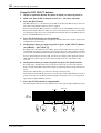
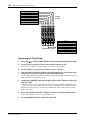
Input Channels
5
MD8—Owner’s Manual
Input Channels
A
GAIN control
This rotary control adjusts the sensitivity of the MIC/LINE input so that both
microphone and line-level signals can be handled with ease.
B
FLIP switch
This switch is used to select the signal sources for the input channel and CUE con-
trols. With the [FLIP] switch in the up position, the MIC/LINE input signal is
fed to the input channel and the track signal is fed to the CUE controls. With the
[FLIP] switch in the down position, however, this is reversed: the MIC/LINE
input signal is fed to the CUE controls and the track signal is fed to the input
channel.
C
CUE PAN & LEVEL controls
These two controls are used to adjust the level and pan of the CUE signal. The
CUE signal source depends on the [FLIP] switch. With the [FLIP] switch set to
the up position, the signal source is the track (i.e., the signal being recorded or
played back). With the [FLIP] switch set to the down position, the CUE signal
source is the MIC/LINE inputs. This setting is typically used during mixdown,
when the track signal is fed through the input channel. This allows you to connect
extra sound sources during mixdown and set their level and pan position using
the CUE controls.
D
EQ controls
These rotary controls are used to boost and cut the high, middle, and low fre-
quency bands independently. The High and Low EQs are fixed frequency shelving
types. The Mid EQ is a sweepable peaking type. A flat setting (i.e., no boost or
cut) can be set quickly using the controls’ center detents.
E
AUX controls
These rotary controls are used to send the input channel signal to the AUX SEND
outputs for processing by external effects processors.
LINE
GAIN
HIGH
MID
LOW
AUX
PAN
MIC
LR
1
10
9
8
7
6
5
4
3
2
1
0
–15 +15
–15 +15
–15 +15
250 5k
FLIP
PB MIC/
LINE
CUE
010
F
G
1
010
2
010
1 2
3 4
GROUP ASSIGN
L
ODD
R
EVEN
P
A
N
L
E
V
E
L
1
7
8
2
3
5
6
4
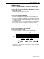
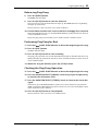
Sweepable range
Response [dB]
Frequency [Hz]
+5
+10
+15
–15
–10
–5
0
10k1k100 20k20
HIGH ±15 dB at 12 kHz—shelving type
MID ±15 dB at 250 Hz–5 kHz—sweepable peaking type
LOW ±15 dB at 80 Hz—shelving type

6
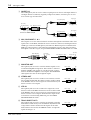
Touring the MD8
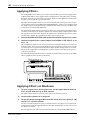
MD8—Owner’s Manual
F
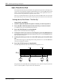
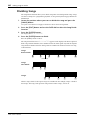
GROUP ASSIGN switches
These switches are used to assign (i.e., send) the input channel signal to groups. They work
in conjunction with the PAN control. For example, with GROUP ASSIGN switch [1–2] ON
and the PAN control set midway, the channel signal is sent equally to Groups 1 and 2. With
the PAN control turned fully counterclockwise (L/ODD), however, the channel signal is sent
only to Group 1. Likewise, when it is set fully clockwise, the signal is sent only to Group 2.
The same principle applies to GROUP ASSIGN switch [3–4]. Note that input channel signals
are always sent to the Stereo bus regardless of the GROUP ASSIGN switch settings.
G
PAN control
This rotary control has two functions: For recording it’s used in conjunction with the
GROUP ASSIGN switches to assign the input channel signal to even and odd numbered
groups. For mixdown it’s used to pan (i.e., position) the signal in the stereo mix.
H
Fader
This fader has two functions: For recording it’s used to adjust the level of the input channel
signal that’s recorded to a track. For mixdown it’s used to balance the input channel signal
relative to the other input channel signals. For optimum performance, faders should be posi-
tioned about the 7–8 mark.

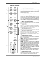
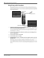
Master Section
7
MD8—Owner’s Manual
Master Section
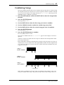
A
9–10/11–12 input level controls
These rotary controls are used to adjust the level of the 9–10 and
11–12 input signals that are sent to the Stereo bus for mixing.
They’re also used in conjunction with the GROUP ASSIGN
switches to adjust the level of the 9–10 and 11–12 input signals
that are assigned to groups.
B
9–10/11–12 GROUP ASSIGN switches
These switches are used to assign (i.e., send) the 9–10 and 11–12
input signals to the groups. The left-channel signal is sent to odd
Groups 1 and 3, while the right-channel signal is sent to even
Groups 2 and 4. The 9–10 and 11–12 input signals could be the
stereo output signals from another mixer or external effects pro-
cessor. Note that the 9–10 and 11–12 input signals are always sent
to the Stereo bus for mixing regardless of these switch settings.
C GROUP MASTER level controls
These rotary controls adjust the levels of the group signals that
are fed to the tracks.
D STEREO fader
This fader is used to adjust the level of the stereo signal that is
sent to the STEREO OUT jacks. For optimum performance this
fader should be positioned about the 7–8 mark.
E CUE MASTER level control
This control is used to adjust the overall level of the CUE signal.
F CUE MIX TO STEREO switch
This switch is used to feed the CUE bus signals through to the
Stereo bus (i.e., the CUE bus signals are mixed with the
MIC/LINE signals). It’s used for multi-source mixing at mix-
down.
G MONITOR SELECT switches
These switches are used to select the signal source for the MON-
ITOR OUT and headphones.
2TR IN—This switch selects the 2TR IN as the monitor source.
This allows you to monitor the output of a stereo master
recorder during mixdown.
GROUP—These switches select the Group buses as the moni-
tor source. This allows you to monitor signals assigned to tracks.
When only the [1–3] or [2–4] switch is pressed, the monitor sig-
nal is mono. Press both switches to monitor stereo signals.
STEREO—This switch selects the Stereo bus as the monitor
source. This allows you to monitor the STEREO OUT signal and
is typically used during mixdown.
CUE—This switch selects the CUE bus as the monitor source.
This allows you to monitor track signals, which is useful for
punch in/out.
H MONITOR LEVEL control
This rotary control adjusts the level of the monitor signal that is
sent to the MONITOR OUT and PHONES connectors.
1
1
2
3
4
2 1 2
3 4 3 4
GROUP ASSIGN GROUP ASSIGN
1 3
2 4
GROUP
2TR IN
MONITOR
SELECT
CUE MIX
TO STEREO
CUE
MASTER
GROUP
MASTER
STEREO
CUE
010 010
010
010
010
010
010
MONITOR
LEVEL
MIN MAX
9-10
STEREO
11-12
10
9
8
7
6
5
4
3
2
1
0
10
9
8
7
6
5
4
3
2
1
0
1
5
8
6
7
4
2
3

8 Touring the MD8
MD8—Owner’s Manual
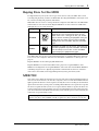
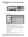
Display
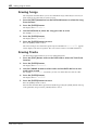
A Status indicators
These indicators show the current operating mode.
B Pitch indicators
These indicators show the current Pitch mode: FIX (fixed) or VARI (variable).
C MTC, MIDI CLK, and MMC indicators
These indicators light when the MIDI synchronization options are used. MTC appears when
the MD8 is generating MIDI Timecode, MIDI Clock appears when it’s generating MIDI
Clock, and MMC appears when the MD8 is set to receive MIDI Machine Control com-
mands. Normally, playback continues through all the songs on a disc. When one of these
indicators is lit, however, playback stops when the end of a song is reached. Use the [SONG
SEARCH] buttons to select other songs.
D TOC EDIT indicator
The TOC EDIT indicator lights when the TOC needs to be updated, usually after a new
recording or edit.
E Time Counter mode
These indicators show the Time Counter mode. When a MIDI tempo map is used, the dis-
play shows measure and beat information.
ELAPSE—This mode shows the time position within a song.
Indicator Meaning
Normal playback
Cue or Review
Playback is paused
Rehearse Pause mode
Rehearsal in progress
Record Pause mode
Recording in progress
S 1 2 3 4 5 6 7 8 9 10 E IN OUT
TOC
EDIT
REC
MTC
MIDI CLK
MMC
PITCH
FIX VARI
REHE
REPEAT
A1ALLB
MARKERS
AUTO PUNCH
1 2 3 4 5 6 7 8
CLIP
–3
–6
–12
–18
–24
–36
+12
+6
+3
0
–6
–10
–20
ELAPSE
TOTAL
REMAIN
MEASURE MIN. BEAT SEC. FRAMES
DIR
GRP
TRK
dB L R
STEREO
MD8 Song
6
5
7
8 9
K NMLJ
4
3
1
2
REHE
REHE
REC
REC

Display 9
MD8—Owner’s Manual
REMAIN—This mode shows the time remaining for a song or when you are recording a
new song, it shows the available time remaining for the song (on disc).
TOTAL—This mode shows the time position within the entire disc.
F Title and function display
Disc titles, song titles, functions, messages, and other information appear here.
G Time counter
The time counter shows the disc time in minutes, seconds, and frames (1/86 second or 1/30
second). When the MIDI tempo map is used, the display shows measure and beat informa-
tion.
H Track level meters
These track level meters show group signal levels in seven steps from –36 dB to CLIP. With
no disc loaded, the meters display group signal levels.
I Stereo level meters
These level meters show the STEREO OUT signal levels from –20 dB to +12 dB in seven
steps.
J Repeat mode indicators
These indicators show the Repeat modes.
REPEAT 1—The current song is played repeatedly (One Song Repeat).
REPEAT ALL—All songs are played repeatedly (All Song Repeat).
REPEAT A–B—Playback cycles between points A and B (A–B Repeat).
REPEAT Auto Punch I/O—Auto Punch In/Out is rehearsed repeatedly.
K Markers
These indicators show the status of the Start, End, and 10 markers in between. When a song
is recorded, Start and End markers are recorded automatically. You can also add up to 10
markers per song while recording is in progress or during subsequent playback. When a song
is positioned on or after a marker (stopped, playing, paused, or recording) that marker
flashes. When the beginning of a song is located, the Start marker flashes. When the end is
located, the End marker flashes.
L AUTO PUNCH indicator
The AUTO PUNCH indicator shows that the AUTO PUNCH In/Out function is on.
M IN & OUT indicators
The IN and OUT indicators light up when the LAST REC IN and OUT points have been
set. When a song is positioned on or after the IN or OUT point, the corresponding indicator
flashes.
IN—This indicator lights up when the LAST REC IN point has been set. When the Auto
Punch function is on, it goes off when a song is located on or after the specified IN point.
OUT—This indicator lights up when the LAST REC OUT point has been set. When the Auto
Punch function is on, it goes off when a song is located on or after the specified OUT point.
N Track record indicators
These indicators show which tracks are selected for recording. The DIR indicators light up
when the input channel signal is selected for direct recording, and the GRP indicators light
up when the group signal is selected for recording.

10 Touring the MD8
MD8—Owner’s Manual
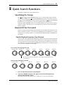
Disc Transport Section
A Disc Transport buttons
REHE—This button is used to enter Rehearse mode. The REHE indicators flash in Rehearse
Pause mode and stay on continuously while rehearsal is in progress.
REC—This button is used to enter Record mode. The REC indicators flash in Record Pause
mode and stay on continuously while recording is in progress.
PLAY—This button is used to start normal playback, start rehearsal, and start recording. It
can also be used to cancel rehearsal and recording. In this case, normal playback continues
from the point at which the [PLAY] button is pressed. The PLAY indicators light up while
playback is in progress and flash when playback is paused.
PAUSE—This button is used to pause playback, recording, or rehearsal.
STOP/TOC WRITE—This button is used to stop playback, rehearsal, and recording. It’s
also used to write the TOC data to disc when the MD8 is stopped.
B AUTO PUNCH I/O button
This button is used to turn on the Auto Punch In/Out function.
C SONG SEARCH buttons
These buttons are used to search for songs.
D LAST REC SEARCH IN/OUT & SET buttons
The SET button is used in combination with the LAST REC SEARCH IN/OUT buttons to
set the LAST REC IN/Punch In and OUT/Punch Out points. The LAST REC SEARCH
IN/OUT buttons are used to locate the LAST REC IN and OUT points.
GROUP 1
CH 1 CH 2 CH 3 CH 4 CH 5 CH 6 CH 7 CH 8
2345678
REC SELECT
DISPLAY
REPEAT MARK SEARCH MARK
AUTO
PUNCH I/O SONG SEARCH PAUSE
REHE REC PLAY STOP
A B LAST REC SEARCH SET EXIT
ADJUSTPITCH EDIT UTILITY
ENTER
PHONES PUNCH I/O
DATA
+ –
CURSOR
12341234
TOC WRITE
8
9
6
5
2
3
O
M
K
L
N
1
4
7
J
IN OUT

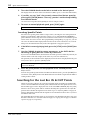
Disc Transport Section 11
MD8—Owner’s Manual
E A B Repeat buttons
These buttons are used to enter the A and B points for A-B Repeat.
F REPEAT button
This button is used to select the 1 Song, All Song, A-B, and Auto Punch Rehearse Repeat
modes. It’s also used to cancel A-B Repeat mode.
G MARK SEARCH & MARK buttons
The MARK SEARCH buttons are used to locate song markers. The MARK button is used
to enter markers during recording or playback.
H DISPLAY button
This button is used to select the Time Counter mode: ELAPSE, REMAIN, or TOTAL. When
the MIDI tempo map is used, the display shows measure and beat information.
I GROUP button
Used in combination with the REC SELECT buttons, this button is used to set tracks to
record group signals.
J REC SELECT buttons
These buttons are used to select tracks for recording. Pressing a REC SELECT button on its
own sets the corresponding track to record input channel signals (DIR). Holding down the
GROUP button and pressing a REC SELECT button sets the corresponding track to record
group signals (GRP).
K EJECT button
This button is used to eject the disc.
L Function buttons
PITCH—This button is used to access the Pitch function. Depending on how you set this
function, the FIX (fixed) or VARI (variable) indicator lights (see page 87).
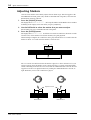
ADJUST—This button is used to adjust the position of markers and the LAST REC IN and
OUT points.
EDIT—This button is used to access the Part Copy, Part Erase, Track Copy, Track Erase, Song
Copy, Song Erase, Song Tempo, Song Divide, Song Combn, Song Move, Song Renum, Song
Name, Disc Erase, and Disc Name functions.
UTILITY—This button is used to access the following functions: Rec Mode, PrePost Roll,
Cue List, Prog Play, MIDI Sync, MMC Receive, MMC Dev ID, Frame Disp, Disp Dimmer,
Peak Hold, and Disc Info.
M ENTER button
This button is used to set functions.
N EXIT button
This button is used to cancel functions and modes.
O CURSOR shuttle/DATA dial
The central dial (called DATA) is used to set and select parameters (+/– DATA). When the
MD8 is stopped or paused, the DATA dial can be used to move through a song in frame steps.
The outer shuttle (CURSOR) is used to select items on the display. When the MD8 is stopped
or paused, the shuttle can be used to move through a song at high speed. During playback,
it can be used for cue and review at 0.5x, 2x, 4x, 8x, 16x, or 32x playback speed (0.5x cue
only).
When using cue or review, the time counter may stop occasionally.
Note: If you press the EJECT button while TOC EDIT is shown on the display, the disc
will not eject. Press [TOC WRITE] to update the TOC, and then eject the disc.

12 Touring the MD8
MD8—Owner’s Manual
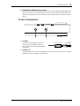
Rear Panel
A AC IN
Connect the supplied power cord here.
B POWER ON/OFF switch
This switch is used to turn on and off the MD8.
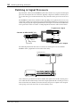
C MIDI IN, OUT & THRU
The MD8 receives MMC (MIDI Machine Control) commands via the MIDI IN port, and
outputs MIDI Clock or MTC (MIDI Timecode) from the MIDI OUT port. The MIDI THRU
port outputs MIDI data received at the MIDI IN port.
AC IN THRU OUT
MIDI
IN
POWER
ON OFF
1 2 3
CAUTION
TO PREVENT ELECTRIC SHOCK,
MATCH WIDE BLADE OF PLUG TO
WIDE SLOT, FULLY INSERT.
La pagina sta caricando ...
La pagina sta caricando ...
La pagina sta caricando ...
La pagina sta caricando ...
La pagina sta caricando ...
La pagina sta caricando ...
La pagina sta caricando ...
La pagina sta caricando ...
La pagina sta caricando ...
La pagina sta caricando ...
La pagina sta caricando ...
La pagina sta caricando ...
La pagina sta caricando ...
La pagina sta caricando ...
La pagina sta caricando ...
La pagina sta caricando ...
La pagina sta caricando ...
La pagina sta caricando ...
La pagina sta caricando ...
La pagina sta caricando ...
La pagina sta caricando ...
La pagina sta caricando ...
La pagina sta caricando ...
La pagina sta caricando ...
La pagina sta caricando ...
La pagina sta caricando ...
La pagina sta caricando ...
La pagina sta caricando ...
La pagina sta caricando ...
La pagina sta caricando ...
La pagina sta caricando ...
La pagina sta caricando ...
La pagina sta caricando ...
La pagina sta caricando ...
La pagina sta caricando ...
La pagina sta caricando ...
La pagina sta caricando ...
La pagina sta caricando ...
La pagina sta caricando ...
La pagina sta caricando ...
La pagina sta caricando ...
La pagina sta caricando ...
La pagina sta caricando ...
La pagina sta caricando ...
La pagina sta caricando ...
La pagina sta caricando ...
La pagina sta caricando ...
La pagina sta caricando ...
La pagina sta caricando ...
La pagina sta caricando ...
La pagina sta caricando ...
La pagina sta caricando ...
La pagina sta caricando ...
La pagina sta caricando ...
La pagina sta caricando ...
La pagina sta caricando ...
La pagina sta caricando ...
La pagina sta caricando ...
La pagina sta caricando ...
La pagina sta caricando ...
La pagina sta caricando ...
La pagina sta caricando ...
La pagina sta caricando ...
La pagina sta caricando ...
La pagina sta caricando ...
La pagina sta caricando ...
La pagina sta caricando ...
La pagina sta caricando ...
La pagina sta caricando ...
La pagina sta caricando ...
La pagina sta caricando ...
La pagina sta caricando ...
La pagina sta caricando ...
La pagina sta caricando ...
La pagina sta caricando ...
La pagina sta caricando ...
La pagina sta caricando ...
La pagina sta caricando ...
La pagina sta caricando ...
La pagina sta caricando ...
La pagina sta caricando ...
La pagina sta caricando ...
La pagina sta caricando ...
La pagina sta caricando ...
La pagina sta caricando ...
La pagina sta caricando ...
La pagina sta caricando ...
La pagina sta caricando ...
La pagina sta caricando ...
La pagina sta caricando ...
La pagina sta caricando ...
La pagina sta caricando ...
La pagina sta caricando ...
La pagina sta caricando ...
La pagina sta caricando ...
-
 1
1
-
 2
2
-
 3
3
-
 4
4
-
 5
5
-
 6
6
-
 7
7
-
 8
8
-
 9
9
-
 10
10
-
 11
11
-
 12
12
-
 13
13
-
 14
14
-
 15
15
-
 16
16
-
 17
17
-
 18
18
-
 19
19
-
 20
20
-
 21
21
-
 22
22
-
 23
23
-
 24
24
-
 25
25
-
 26
26
-
 27
27
-
 28
28
-
 29
29
-
 30
30
-
 31
31
-
 32
32
-
 33
33
-
 34
34
-
 35
35
-
 36
36
-
 37
37
-
 38
38
-
 39
39
-
 40
40
-
 41
41
-
 42
42
-
 43
43
-
 44
44
-
 45
45
-
 46
46
-
 47
47
-
 48
48
-
 49
49
-
 50
50
-
 51
51
-
 52
52
-
 53
53
-
 54
54
-
 55
55
-
 56
56
-
 57
57
-
 58
58
-
 59
59
-
 60
60
-
 61
61
-
 62
62
-
 63
63
-
 64
64
-
 65
65
-
 66
66
-
 67
67
-
 68
68
-
 69
69
-
 70
70
-
 71
71
-
 72
72
-
 73
73
-
 74
74
-
 75
75
-
 76
76
-
 77
77
-
 78
78
-
 79
79
-
 80
80
-
 81
81
-
 82
82
-
 83
83
-
 84
84
-
 85
85
-
 86
86
-
 87
87
-
 88
88
-
 89
89
-
 90
90
-
 91
91
-
 92
92
-
 93
93
-
 94
94
-
 95
95
-
 96
96
-
 97
97
-
 98
98
-
 99
99
-
 100
100
-
 101
101
-
 102
102
-
 103
103
-
 104
104
-
 105
105
-
 106
106
-
 107
107
-
 108
108
-
 109
109
-
 110
110
-
 111
111
-
 112
112
-
 113
113
-
 114
114
-
 115
115


Yamaha MD 8 Manuale utente
- Categoria
- Strumenti musicali
- Tipo
- Manuale utente
- Questo manuale è adatto anche per
in altre lingue
- English: Yamaha MD 8 User manual
- français: Yamaha MD 8 Manuel utilisateur
- español: Yamaha MD 8 Manual de usuario
- Deutsch: Yamaha MD 8 Benutzerhandbuch
- русский: Yamaha MD 8 Руководство пользователя
- Nederlands: Yamaha MD 8 Handleiding
- português: Yamaha MD 8 Manual do usuário
- dansk: Yamaha MD 8 Brugermanual
- čeština: Yamaha MD 8 Uživatelský manuál
- polski: Yamaha MD 8 Instrukcja obsługi
- svenska: Yamaha MD 8 Användarmanual
- 日本語: Yamaha MD 8 ユーザーマニュアル
- Türkçe: Yamaha MD 8 Kullanım kılavuzu
- română: Yamaha MD 8 Manual de utilizare