Mitsubishi Electric GRAPHIC FX DU UNITS Manuale del proprietario
- Tipo
- Manuale del proprietario

MELSEC-F
HARDWARE MANUAL
GRAPHIC FX DU UNITS
La pagina sta caricando ...

Hardware Manual
Manuel du matériel
Graphic FX DU Units
Hardware-Handbuch
Manuale hardware
Manual de Hardware
Manual number: JY992D42601
Manual revision: D
Date: October 1995
Graphic FX DU Units
i

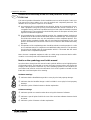
Guidelines for the safety of the user and protection of the Graphic
FX DU Unit
This manual provides information for the installation and use of the Graphic FX DU Unit.
The manual has been written to be used by trained and competent personnel. The
definition of such a person or persons is as follows;
a)
Any engineer who is responsible for the planning, design and construction of auto-
matic equipment using the product associated with this manual should be of a
competent nature, (trained and qualified to the local and national standards required
to fulfil that role). These engineers should be fully aware of all aspects of safety with
regards to automated equipment.
b)
Any commissioning or service engineer must be of a competent nature, trained and
qualified to the local and national standards required to fulfil that job. These engineers
should also be trained in the use and maintenance of the completed product. This
includes being completely familiar with all associated documentation for the said
product. All maintenance should be carried out in accordance with established safety
practices.
c)
All operators of the completed product should be trained to use that product in a safe
and co-ordinate manner in compliance to established safety practices. The operators
should also be familiar with all documentation which is connected with the actual
operation of the completed equipment.
Note: the term ’completed equipment’ refers to a third party constructed device which
contains or uses the product associated with this manual.
Note’s on the symbology used in this manual
At various times through out this manual certain symbols will be used to highlight points
of information which are intended to ensure the users personal safety and protect the
integrity of the equipment. Whenever any of the following symbols are encountered, its
associated note must be read and understood. Each of the symbols used will now be
listed with a brief description of its meaning.
Hardware warnings
1)
Indicates that the identified danger WILL cause physical and property damage.
2)
Indicates that the identified danger could POSSIBLY cause physical and property
damage.
3)
Indicates a point of further interest or further explanation.
Software warnings
4)
Indicates special care must be taken when using this element of software.
5)
Indicates a special point of which the user of the associate software element should
be aware.
6)
Indicates a point of interest or further explanation.
ENG
Graphic FX DU Units
ii
La pagina sta caricando ...
La pagina sta caricando ...
La pagina sta caricando ...

Instrucciones de seguridad para el usuario y medidas de
protección para la unidad gráfica de mando
Este manual comprende las informaciones correspondientes para la instalación y el uso
de la unidad gráfica de mando. El manual ha sido elaborado para un empleo por personal
competente y capacitado. Al respecto se establece la siguiente definición en cuanto a la
calificación de los operadores:
a)
Todo técnico, encargado de la planificación, proyección y construcción de instalacio-
nes de la técnica de automatización en función del producto deberá disponer de
conocimientos satisfactorios sobre el tema. Además, la formación y calificación
deberá abarcar también el campo de las normas competentes locales y nacionales.
El técnico deberá disponer también de plenos conocimientos sobre todos los aspec-
tos relacionados con la seguridad en el sector de técnica de automatización.
b)
Todo técnico encargado de la puesta en servicio o del servicio postventa tiene que
conocer las disposiciones locales y nacionales relacionadas con la ejecución correcta
y segura de las operaciones. El técnico también tiene que haber sido formado en el
manejo y mantenimiento de las unidades de producción. Esto encuentra aplicación
para toda la familia de productos con todas las respectivas documentaciones. Todas
las unidades de mantenimiento se deberán realizar siempre de acuerdo con las
instrucciones y reglamentos de seguridad corrientes.
c)
Todo operario de la unidad deberá disponer de la formación correspondiente que le
permita un manejo seguro de la unidad. Asimismo se deberán observar en todo
momento las disposiciones de seguridad corrientes. El operario se tiene que familiari-
zar también con el contenido de la documentación de las otras unidades de la instalación.
Nota: Bajo la expresión "las otras unidades de la instalación" se entienden todas las
demás unidades de la instalación de automatización, que están relacionadas con el
producto y con las respectivas informaciones en el manual.
Observaciones sobre los símbolos empleados en este manual
En este manual se emplean diversos símbolos que permiten resaltar informaciones
determinadas. La finalidad de los símbolos es aclarar a los operarios las correspondientes
indicaciones de seguridad y de medidas de protección. Cada vez que se presente un
símbolo, se tiene que leer la indicación pertinente, teniéndose que entender la informa-
ción recibida. A continuación se expone una relación de todos los símbolos con una breve
descripción de su significado.
Indicaciones de aviso del Hardware
1)
Indica un peligro inminente, que conduce a daños personales o materiales.
2)
Indica la posibilidad de un peligro, que conduce a daños personales o materiales.
3)
Indica un punto con indicaciones o aclaraciones adicionales.
Indicaciones de aviso del software
4)
Señala una indicación especial, que tiene que ser observada en todo caso al
emplearse el elemento de software.
5)
Señala una indicación especial, que deberá ser observada por el usuario junto con
el elemento de software pertinente.
6)
Señala un punto con indicaciones o aclaraciones adicionales.
ESP
Graphic FX DU Units
vi
La pagina sta caricando ...
La pagina sta caricando ...

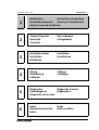
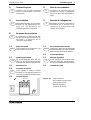
Introduction Instructions de montage
Installationshinweise Avvisi per l’installazione
Instrucciones de instalación
1
Terminal Layouts Raccordement
Anschluß Collegamenti
Conexión
2
3
Installation Notes Installation
Installation Installazione
Instalación
Wiring Câblage
Verdrahtung Cablaggio
Cableado
4
Diagnostics Diagnostic d’erreur
Fehlerdiagnose Diagnostica
Diagnóstico de averías
5
Index Index
Stichwortverzeichnis Indice analitico
Indice
6
Graphic FX DU Units Introduction
1
1 – 1

Graphic FX DU Units Introduction
1
1 – 2
La pagina sta caricando ...

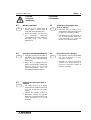
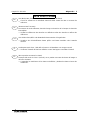
1.1
The Complete Family Of Data
Access Units
1.1
La famille complète des appareils
de commande graphiques
1.1
Die komplette Familie der
grafischen Bediengeräte
1.1
L’intera famiglia degli
apparecchi video grafici
1.1
La familia completa de las
unidades gráficas de mando
ESP
ITLGER
FREENG
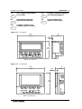
UNITS: mm (inches)
POWER
CLEAR SET/- SHIFT ENTER
0 1 2 3 4
5 6 7 8 9
78
(3.07)
5
(0.20)
186
(7.32)
125
(4.92)
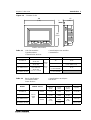
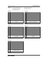
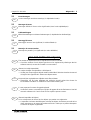
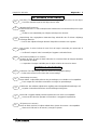
Figure: 1.1 FX-30DU-E
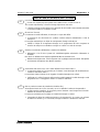
0/A 1/B 2/C 3/D 4/E
5/F 6 7 8 9
POWER CLEAR SET / - SHIFT ENTER
186
(7.32)
11.5
(0.45)
62
(2.44)
151
(5.94)
UNITS: mm (inches)
Figure: 1.2 FX-40DU-ES
Graphic FX DU Units Introduction
1
1 – 4

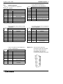
MODEL SCREEN TYPE KEYS
IP RATING
FX-30DU-E
240 ×64 dots
30 ×4 char
BLUE
LCD
BACK
LIT
16 IP 65
FX-40DU-ES
240 ×128 dots
30 ×7 char
16
IP 54
(+ FX-40DU-COV)
FX-40DU-TK-ES
240 ×128 char
30 ×7 char
TOUCH SCREEN
6
(+ 32 SCREEN)
IP 54
FX-40DU-TK-ES
+FX-40DU-TK-KP
16
(+ 32 SCREEN)
Table: 1.1 Unit Characteristics Caractéristiques des modéles
Typenkenndaten Caratteristiche
Características técnicas
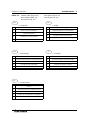
MODEL POWER SUPPLY
DIMENSIONS WEIGHT
W mm
(inch)
H mm
(inch)
D mm
(inch)
kg (lbs)
FX-30DU-E
24V DC
+10%
15%
200mA
186
(7.32)
125
(4.92)
78
(3.07)
0.9 (1.98)
FX-40DU-ES 220mA
186
(7.32)
151
(5.94)
62
(2.44)
1.0 (2.2)
FX-40DU-TK-ES
220mA
186
(7.32)
140
(5.51)
65
(2.56)
1.0 (2.2)
FX-40DU-TK-ES
+FX-40DU-TK-KP
184
(7.24)
1.0 (2.2)+
<0.1 (0.22)
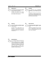
Table: 1.2 Basic Specifications Caractéristiques techniques
Technische Daten Dati tecnici
Datos técnicos
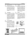
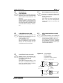
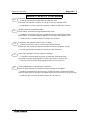
UNITS: mm (inches)
65
(2.56)
5
(0.2)
186
(7.32)
140
(5.51)
POWER
CLEAR SET/-
SHIFT ENTER
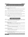
Figure: 1.3 FX-40DU-TK-ES
Graphic FX DU Units Introduction
1
1 – 5

1.2
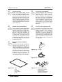
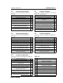
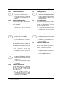
Unit Accessories
Each of the Graphic Data Access
Units comes with the following acces-
sories. The battery F2-40BL is inside
the unit and can be replaced by fol-
lowing the instructions later in this
manual (Page 5-5). The cable FX-
40DU-CAB and brackets and screws
are also included with each unit. A
seal is provided with each unit except
the FX-40DU-ES.
1.2
Accessoires d’un appareil
Chaque appareil de commande
graphique est livré avec les acces-
soires suivants. La pile F2-40BL se
trouve à l’intérieur de l’appareil et
peut être échangée conformément
aux instructions de la page 5-5.
Chaque appareil comprend égale-
ment le câble FX-40DU-CAB, les
supports et les vis. Un joint est prévu
sur chaque unité sauf sur la FX-
40DU-ES.
1.2
Zubehör einer Geräteeinheit
Jede grafische Bediengeräteinheit
wird mit dem folgenden Zubehör aus-
geliefert. Die Batterie F2-40BL befin-
det sich innerhalb des Gerätes und
läßt sich anhand der Hinweise auf
Seite 5-5 austauschen. Das Kabel
FX-40DU-CAB, die Träger und die
Schrauben sind ebenfalls bei jeder
Geräteeinheit enthalten. Bis auf das
FX-40DU-ES liegt Jedem Gerät eine
Ramendichtung bei.
1.2
Accessori per un apparecchio
Ogni apparecchio video grafico viene
fornito con i seguenti accessori. La
batteria F2-40BL si trova all’interno
dell’apparecchio e si può sostituire
seguendo le istruzioni riportate più
avanti a pagina 5-5. Inoltre ogni unità
contiene il cavo FX-40DU-CAB, i sup-
porti e le viti.Tutte le unitá sono mu-
nite di guarnizione eccetto la
FX-40DU-ES.
1.2
Accesorios de una unidad de
mando
Cada una de las unidades gráficas de
mando se suministra con los ac-
cesorios siguientes. La batería F2-
40BL se encuentra dentro de la unidad
y puede ser cambiada observando lo
indicado en la página 5-5. Asimismo se
encuentran en cada unidad el cable
FX-40DU-CAB, los soportes y los
tornillos. Se proporciona un sello con
cada unidad excepto la FX-40DU-ES.
ITL
FREENG
GER
ESP
Figure: 1.4 Seal
Joint
Dachtring
Guarnizione
Junta
Figure: 1.5 F
2
-40BL
Figure: 1.6 FX-40DU-CAB
Figure: 1.7 Mounting Brackets
Support de montage
Montagetärger
Supporti di montaggio
Soporte de montaje
Graphic FX DU Units Introduction
1
1 – 6
La pagina sta caricando ...

1
2
8
7
5
3
6
4
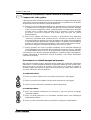
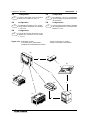
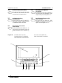
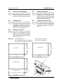
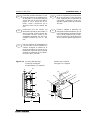
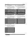
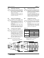
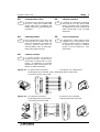
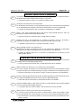
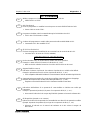
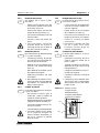
Figure: 1.12 Schematic System Schma de principe du systme
Schematischer Systemaufbau Struttura schematica del sistema
Configuración esquemática del sistema
1.4
Configuration
Product description and connection
details are in table 1.3 and 1.4.
1.4
Configuration
Les tableaux 1.3 et 1.4 contiennent
une description du produit et les dtails
de connexion.
1.4
Konfiguration
Produktbeschreibung und Verbin-
dungs details enthalten die Tabellen
1.3 und 1.4.
1.4
Configurazione
La descrizione del prodotto e i dettagli
dei collegamenti sono contenuti nelle
tabelle 1.3 e 1.4.
1.4
Configuración
Para la descripción del producto y los
detalles de conexión ver las tablas
1.3 y 1.4.
ESP
ITLGER
FREENG
(A)
(C)
(D)
(B)
(E)
(G)
(F)
Graphic FX DU Units Introduction
1
1 – 8

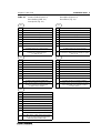
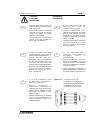
Table: 1.3 Product Description Description du produit
Produktbeschreibung Descrizione del prodotto
Descripción del producto
ENG
(see figure 1.12)
A FX Graphic Display Unit
B FX, FX2C or A series PLC to monitor
C FX0 series PLC to monitor
D
Serial Printer to print data logging and screen
data. Must be Epson ESC/P compatible.
E
IBM PC compatible to create, read and write
screen data. FX-PCS-DU/AT-EE software
F EPROM Writer to store screen data.
G EPROM: Type 27C512
(voir figure 1.12)
A Appareil de commande graphique
B API-FX, FX2C ou de série A pour la surveillance
C API de la série FX0 pour la surveillance
D
Imprimante série pour l’impression des mesures
et des données-image (appareils compatibles
Epson-ESC/P uniquement).
E
PC avec système d’exploitation MS DOS pour la
création, la lecture et l’écriture des données-
image. Logiciel FX-PCS-DU/AT-EE
F
Enregistreur d’EPROM pour la mémorisation
des données-image.
G EPROM: 27C512
ESP
ITLGER
FRE
(siehe Abbildung 1.12)
A Grafisches Bediengerät
B
FX-, FX2C- oder A-Serien-SPS zum
Überwachen
C SPS der FX0-Serie zum Überwachen
D
Serieller Drucker zum Drucken der Meß- und
Bilddaten (nur Epson-ESC/P-kompatibele
Geräte).
E
PC mit MS DOS-Betriebssystem zum Erstellen,
Lesen und Schreiben der Bilddaten. FX-PCS-
DU/AT-EE-Software
F EPROM-Schreiber zum Speichern der Bilddaten.
G EPROM: Typ 27C512
(v. fig. 1.12)
A Apparecchio video grafico
B PLC di controllo FX, FX2C o serie A
C PLC di controllo della serie FX0
D
Stampante seriale per la stampa dei dati di
misura e dei dati grafici (solo apparecchi Epson-
ESC/P compatibili).
E PC con sistema operativo MS DOS per creare
F
Unità di scrittura EPROM per memorizzare i dati
grafici.
G EPROM: 27C512
(ver la fig. 1.12)
A Unidad gráfica de mando
B SPS de serie FX, FX2C o A para la supervisión
C SPS de la serie FX0 para la supervisión
D
Impresora en serie para la impresión de los
datos de medición y de imagen (solamente
impresoras compatibles con Epson-ESC).
E
Ordenador (PC) con sistema operativo MS-DOS
para la elaboración
F
Registrador EPROM para el almacenamiento de
los datos de imagen.
G Memoria EPROM: 27C512
Graphic FX DU Units Introduction
1
1 – 9

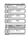
Table: 1.4 Connection Details Connexions possibles
Verbindungsmöglichkeiten Possibilità di collegamento
Posibilidades de conexión
(see figure 1.12)
1 FX-40DU-CAB
2
FX-40DU-CAB + FX-422AW0 (Prefered method)
or FX-40DU-CAB + FX-20P-CADP
3
F2-232CAB or compatible RS232 cable
4
5
6
Connect according to the specifications of the
ROM Writer
7
After programming the EPROM insert in the
socket in the back of Data Access unit
8
ENG
ESP
ITLGER
FRE
(voir figure 1.12)
1 FX-40DU-CAB
2
FX-40DU-CAB et FX-422AW0 (Méthode à adopter)
FX-40DU-CAB et FX-20P-CADP
3
F2-232CAB ou câble RS232 compatible
4
5
6
Connexion conforme aux caractéristiques
techniques de l’enregistreur de ROM
7
Placer l’EPROM dans le socle à l’arrière de
l’appareil après la programmation.
8
(siehe Abbildung 1.12)
1 FX-40DU-CAB
2
FX-40DU-CAB und FX-422AW0 (bevorzugte methode)
FX-40DU-CAB und FX-20P-CADP
3
F2-232CAB oder kompatibles RS232-Kabel
4
5
6
Verbindung gemäß der technischen Daten des
ROM-Schreibgerätes
7
EPROM nach der Programmierung in den
Sockel auf der Geräterückseite setzen.
8
(v. fig. 1.12)
1 FX-40DU-CAB
2
FX-40DU-CAB ed FX-422AW0 (metodo preferito)
FX-40DU-CAB ed FX-20P-CADP
3
F2-232CAB o cavo RS232 compatibile
4
5
6
Collegamento in conformità ai dati tecnici
dell’unità di scrittura ROM
7
Dopo la programmazione inserire l’EPROM
nello zoccolo sul retro dell’apparecchio.
8
(ver la fig. 1.12)
1 FX-40DU-CAB
2
FX-40DU-CAB y FX-422AW0 (Método preferido)
FX-40DU-CAB y FX-20P-CADP
3
F2-232CAB o cable RS232 compatible
4
5
6
Establecer la conexión conforme a lo indicado
en los datos técnicos del aparato registrador
ROM
7 EPROM según la programación en el zócalo
que se encuentra en la parte posterior de la
unidad.
8
Graphic FX DU Units Introduction
1
1 – 10

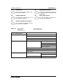
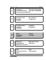
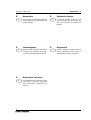
1.5
Function List
Please refer to the DU software man-
ual for further details.
1.5
Diagramme fonctionnel
Pour de plus amples détails, prière de
se reporter au manuel du logiciel de
l’appareil DU.
1.5
Funktionsübersicht
Eingehendere Details finden Sie im
DU-Software-Handbuch.
1.5
Elenco delle funzioni
Per ulteriori dettagli rimandiamo al
manuale del software DU.
1.5
Relación sinóptica de funciones
Ver el manual de software DU para
una información detallada.
ESP
ITLGER
FREENG
USER SCREEN MODE
MONITOR MODE DEVICE
COMMENT/NAME
ON/OFF
STATUS
SAMPLING TRACE SET CONDITION SAMPLE CONDITION
START CONDITION
END CONDITION
SAMPLE DEVICE
DISPLAY LIST
DISPLAY GRAPH
CLEAR DATA
EDIT MODE USER SCREENS COMMON SETTINGS
SCREEN NO.
DATA BANK BANK NO.
Table: 1.5 Menu Options Menu arborescent
Menübaum Opzioni del menu
Arbol de menús
Graphic FX DU Units Introduction
1
1 – 11

MEMO
Graphic FX DU Units Introduction
1
1 – 12

Introduction Instructions de montage
Installationshinweise Avvisi per l’installazione
Instrucciones de instalación
1
Terminal Layouts Raccordement
Anschluß Collegamenti
Conexión
2
3
Installation Notes Installation
Installation Installazione
Instalación
Wiring Câblage
Verdrahtung Cablaggio
Cableado
4
Diagnostics Diagnostic d’erreur
Fehlerdiagnose Diagnostica
Diagnóstico de averías
5
Index Index
Stichwortverzeichnis Indice analitico
Indice
6
Graphic FX DU Units Terminal Layouts
2
2 – 1

Grpahic FX DU Units Terminal Layouts
2
2 – 2
La pagina sta caricando ...

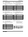
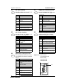
2.2
RS232 Connector
For connection to a printer or
computer.
PIN N°. Name
1 FG Frame Ground
2 RX Receive
3 TX Transmit
4 RTS Request To Send
5 CTS Clear To Send
6 DSR Data Set Ready
7 SG Signal Ground
20 DTR Data Terminal Ready
Pour le branchement d’une
imprimante ou d’un ordinateur.
Broche N°. Désignation
1 FG Terre de l’appareil
2 RX Réception
3 TX Emission
4 RTS Demande d’émission
5 CTS Autorisation d’émission
6 DSR Etat de service
7 SG Terre de signalisation
20 DTR Terminal en ordre de marche
Zum Anschluß eines Druckers oder
Computers.
Pin-Nr. Bezeichnung
1 FG Geräteerde
2 RX Empfangen
3 TX Senden
4 RTS Anforderung zum Senden
5 CTS Freigeben zum Senden
6 DSR Betriebsbereitschaft
7 SG Signalerde
20 DTR Endgerät betriebsbereit
Per l’allacciamento di una stampante
o di un computer.
N°. PIN Designazione
1 FG Massa apparecchio
2 RX Ricevere
3 TX Trasmettere
4 RTS Richiesta di trasmissione
5 CTS Consenso alla trasmissione
6 DSR Unità pronta al funzionamento
7 SG Massa segnale
20 DTR
Terminale pronto al
funzionamento
Para la conexión de una impresora o
de una computadora.
Nº de pin Designación
1 FG Tierra de unidad
2 RX Recepción
3 TX Transmisión
4 RTS Petición de transmisión
5 CTS Habilitación de transmisión
6 DSR Disposición de servicio
7 SG Tierra de señal
20 DTR
Unidad terminal en disposición
de servicio
Figure: 2.2 25 pin D shell connector.
Connecteur gainé D à 25 pôles.
25-poliger D-Mantelstecker.
Connettore a "D" a 25 vie
Conector en D blindado de 25 polos
ESP
ITLGER
FRE
ENG
Grpahic FX DU Units Terminal Layouts
2
2 – 4

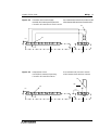
10
01
20 11
(B)
(A)
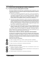
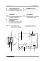
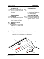
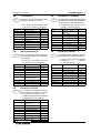
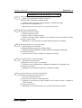
Figure: 2.3 Ribbon Connector
Connecteur pour câble en nappe
Stecker für Flachbandkabel
Connettore per cavo piatto
Conector para cable de cinta plana
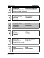
2.3
External I/O connector
Used to connect additional lamps and
switches to the Graphic Data Access
Units.
This connector is not available on the
FX-30DU-E.
Ref. No.
A Sink/Source Switch
B Connector Notch
01,
…
,08 Inputs I0 to I7
09, 10 24V DC +
11,
…
,18 Outputs O0 to O7
19, 20 24V DC –
2.3
Connecteur E/A externe
Pour le raccordement de lampes et
de commutateurs supplémentaires à
l’appareil de commande.
Le FX-30DU-E n’est pas équipé de ce
connecteur.
Ref. No.
A Commutateur émetteur/récepteur
B Pointe du connecteur
01,
…
,08 entrées E0 à E7
09, 10 CC +24 V
11,
…
,18 sorties A0 à A7
19, 20 CC -24 V
2.3
Externer E-/A-Stecker
Zum Anschluß von zusätzlichen
Lampen und Schaltern am Bedi-
engerät.
Dieser Stecker ist am FX-30DU-E
nicht vorhanden.
Ref. No.
A Sink-/Source-Schalter
B Steckernase
01,
…
,08 Eingänge E0 bis E7
09, 10 DC +24 V
11,
…
,18 Ausgänge A0 bis A7
19, 20 DC -24 V
2.3
Connettore I/O esterni
Per l’allacciamento di ulteriori lam-
pade e interruttori con l’apparecchio
video.
Questo connettore non è previsto in
FX- 30DU-E.
Ref. No.
A Interruttore Sink/Source
B Nasello del connettore
01,
…
,08 Ingressi E0
…
E7
09, 10 24 V DC +
11,
…
,18 Uscite A0
…
A7
19, 20 24 V DC -
2.3
Conector de E/S externo
Para la conexión de lámparas e inte-
rruptores adicionales en la unidad de
mando.
Este conector no existe en la FX-
30DU-E.
Ref. No.
A Interruptor Sink-/Source
B Talón de conector
01,
…
,08 Entradas E0 a E7
09, 10 CC +24 V
11,
…
,18 Salidas A0 a A7
19,20 CC -24 V
ESP
ITLGER
FRE
ENG
Graphic FX DU Units Terminal Layouts
2
2 – 5

MEMO
Grpahic FX DU Units Terminal Layouts
2
2 – 6

Introduction Instructions de montage
Installationshinweise Avvisi per l’installazione
Instrucciones de instalación
1
Terminal Layouts Raccordement
Anschluß Collegamenti
Conexión
2
3
Installation Notes Installation
Installation Installazione
Instalación
Wiring Câblage
Verdrahtung Cablaggio
Cableado
4
Diagnostics Diagnostic d’erreur
Fehlerdiagnose Diagnostica
Diagnóstico de averías
5
Index Index
Stichwortverzeichnis Indice analitico
Indice
6
Graphic FX DU Units Installation Notes
3
3 – 1
La pagina sta caricando ...
La pagina sta caricando ...
La pagina sta caricando ...
La pagina sta caricando ...
La pagina sta caricando ...
La pagina sta caricando ...
La pagina sta caricando ...
La pagina sta caricando ...
La pagina sta caricando ...
La pagina sta caricando ...
La pagina sta caricando ...
La pagina sta caricando ...
La pagina sta caricando ...
La pagina sta caricando ...
La pagina sta caricando ...
La pagina sta caricando ...
La pagina sta caricando ...
La pagina sta caricando ...
La pagina sta caricando ...
La pagina sta caricando ...
La pagina sta caricando ...
La pagina sta caricando ...
La pagina sta caricando ...
La pagina sta caricando ...
La pagina sta caricando ...
La pagina sta caricando ...
La pagina sta caricando ...
La pagina sta caricando ...
La pagina sta caricando ...
La pagina sta caricando ...
La pagina sta caricando ...
La pagina sta caricando ...
La pagina sta caricando ...
La pagina sta caricando ...
La pagina sta caricando ...
La pagina sta caricando ...
La pagina sta caricando ...
La pagina sta caricando ...
La pagina sta caricando ...
La pagina sta caricando ...
La pagina sta caricando ...
La pagina sta caricando ...
La pagina sta caricando ...
La pagina sta caricando ...
La pagina sta caricando ...
La pagina sta caricando ...
La pagina sta caricando ...
La pagina sta caricando ...
La pagina sta caricando ...
La pagina sta caricando ...
La pagina sta caricando ...
La pagina sta caricando ...
La pagina sta caricando ...
La pagina sta caricando ...
La pagina sta caricando ...
La pagina sta caricando ...
La pagina sta caricando ...
La pagina sta caricando ...
La pagina sta caricando ...
-
 1
1
-
 2
2
-
 3
3
-
 4
4
-
 5
5
-
 6
6
-
 7
7
-
 8
8
-
 9
9
-
 10
10
-
 11
11
-
 12
12
-
 13
13
-
 14
14
-
 15
15
-
 16
16
-
 17
17
-
 18
18
-
 19
19
-
 20
20
-
 21
21
-
 22
22
-
 23
23
-
 24
24
-
 25
25
-
 26
26
-
 27
27
-
 28
28
-
 29
29
-
 30
30
-
 31
31
-
 32
32
-
 33
33
-
 34
34
-
 35
35
-
 36
36
-
 37
37
-
 38
38
-
 39
39
-
 40
40
-
 41
41
-
 42
42
-
 43
43
-
 44
44
-
 45
45
-
 46
46
-
 47
47
-
 48
48
-
 49
49
-
 50
50
-
 51
51
-
 52
52
-
 53
53
-
 54
54
-
 55
55
-
 56
56
-
 57
57
-
 58
58
-
 59
59
-
 60
60
-
 61
61
-
 62
62
-
 63
63
-
 64
64
-
 65
65
-
 66
66
-
 67
67
-
 68
68
-
 69
69
-
 70
70
-
 71
71
-
 72
72
-
 73
73
-
 74
74
-
 75
75
-
 76
76
-
 77
77
-
 78
78
-
 79
79
-
 80
80
-
 81
81
-
 82
82
-
 83
83
-
 84
84
-
 85
85
-
 86
86
-
 87
87
-
 88
88


Mitsubishi Electric GRAPHIC FX DU UNITS Manuale del proprietario
- Tipo
- Manuale del proprietario
in altre lingue
Documenti correlati
-
Mitsubishi Electric AL-232CAB Manuale del proprietario
-
-
-
Mitsubishi α Series Manuale del proprietario
-
-
-
-